22
(Optional) Connecting the Teamwork Network Cable
7.9
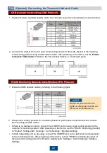
CAN teamwork networking (CAN Protocol)
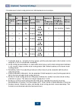
1. Prepare the 8pin standard network cable, the cable pin sequence requirements are shown below.
2. Connect the CAN_OUT port of each smart cooling product to the CAN_IN port of the following
smart cooling product using a CAN network cable. After powering on the device, set the
Enable
teamwork CAN resistor
to
Yes
for the first and last devices in a teamwork group.
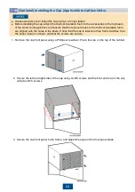
RS485 Monitoring Network Cable (Modbus-RTU Protocol)
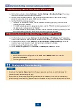
1. Make the COM network cable by referring to the following figure.
Except for pins 4 and 5, the
cable of other pins must be cut
off to prevent interference.
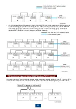
• If there is no teamwork control, connect the COM/FE port on each smart cooling product to the
customer's monitoring system. After powering on the device, set the "RS485 monitoring grouping"
to "Enable". Setting path: Settings > Comm Settings > Modbus Settings.
• In CAN networking and no grouping, connect the COM/FE port on the last smart cooling product
to the monitoring device. After powering on the device, set the "RS485 monitoring grouping" of
the last smart cooling product to "Enable". Setting path: Settings > Comm Settings > Modbus
Settings.
2. Group smart cooling products for monitoring based on performance requirements and connect
the monitoring network cables.

