60
Anti-clockwise
Clockwise
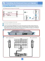
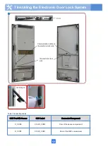
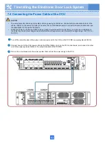
• Connections between the communication cables of the door locks and the CCU depend on actual installation conditions.
The table of connection mappings in the next slide is for reference only.
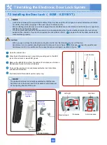
• When installing an electric lock on a cabinet, adjust the door handle based on the direction in which the door is opened so
that the door can be easily opened.
• The lock cylinder and lock body of an electronic lock are delivered together. Decide whether to replace the lock cylinder
based on site conditions. If you decide to replace the lock cylinder, refer to to replace the lock cylinder and keep the
mechanical key properly.
"OK"
When you open or close the cabinet door using the electric lock, the following may occur if the lock
handle lever is not in position (abutting the lock handle), as shown in figure . In this case, you need to press the lock
handle lever until it is in position and then swipe the access card again, as shown in figure .
A
B
A
B
"NOK"
Lock handle
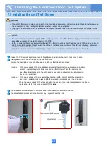
Open the cabinet door.
Wear the ESD wrist strap and connect its grounding end to the ESD
jack on the cabinet, or wear ESD gloves.
Remove the HW-2802 lock from the cabinet. For details, see Common
Maintenance Guide for Outdoor Cabinets.
Take out the electronic lock and disassemble the lock to facilitate
subsequent installation.
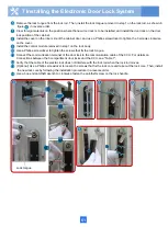
(Optional) Install the restraint part and jump ring.
The restraint part must be correctly assembled so that the lock
handle moves in the same direction (clockwise or anti-clockwise)
as the opening direction of the door.
Restraint part
Left-right
Up-down
Assembled and
delivered
together
Delivered
separately
M5 screw
Control module
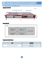
7 Installing the Electronic Door Lock System
7.3 Installing the Door Lock
(
BOM
:
02311EYT
)
Summary of Contents for F01T500
Page 1: ...HUAWEI TECHNOLOGIES CO LTD F01T500 Quick Installation Guide Issue 07 Date 2017 05 03 ...
Page 19: ...With battery cabinet 4 Installing the Cabinet on a Concrete Pedestal 14 ...
Page 23: ...18 Unit mm 4 Installing the Cabinet on a Concrete Pedestal ...
Page 25: ...20 4 Installing the Cabinet on a Concrete Pedestal ...
Page 27: ...22 4 Installing the Cabinet on a Concrete Pedestal ...
Page 38: ...33 With power meter box ...
Page 40: ...35 With power meter box AC power cables AC power cables ...
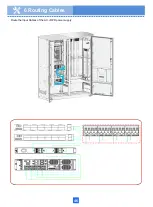
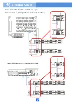
Page 44: ...39 6 Routing Cables 6 3 Diagram of Cable Connections Between the RPS and MDF RPS Power Supply ...
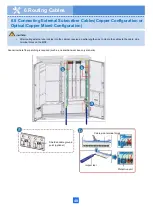
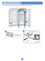
Page 51: ...46 Route the input Cables of the AC RPR power supply 6 Routing Cables ...
Page 83: ...14 FAQs for Installation 78 ...
Page 84: ...15 FAQs for Installation 79 ...

