


3.13.1 Example for Configuring Single-hop BFD for a Layer 3
Physical Link
In this example, a single-hop BFD session to detect faults in a Layer 3 physical link is configured
to rapidly check a direct link on a network.
Networking Requirements
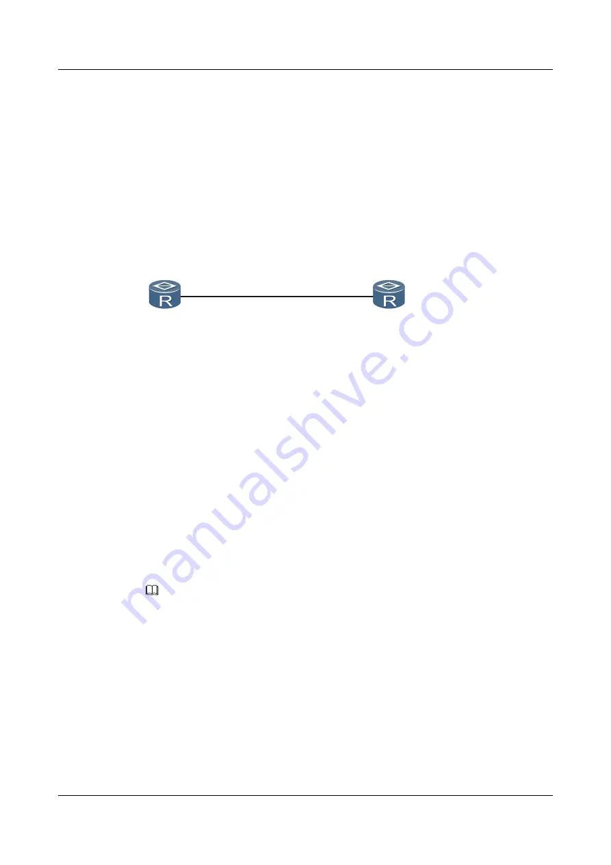
On the network shown in
, a single-hop BFD session is configured to detect a directly
connected link between Router A and Router B.
Figure 3-3
Networking diagram of singe-hop BFD on a Layer 3 link
RouterA
RouterB
GE1/0/0
10.1.1.1/24
GE1/0/0
10.1.1.2/24
Configuration Roadmap
The configuration roadmap is as follows:
1.
Configure a BFD session on Router A to detect the directly-connected link between Router
A and Router B.
2.
Configure a BFD session on Router B to detect the directly-connected link between Router
B and Router A.
Data Preparation
To complete the configuration, you need the following data:
l
Peer IP address for a BFD session
l
Local interface sending and receiving BFD control packets
l
Local and remote discriminators of a BFD session
NOTE
Default values of the minimum sending interval, minimum receiving interval, and local detection multiplier
for BFD control packets are used.
Procedure
Step 1
Configure IP addresses for directly-connected interfaces on Router A and Router B.
# Configure the IP address of the interface on Router A.
<Huawei>
system-view
[Huawei]
sysname RouterA
[RouterA]
interface gigabitethernet 1/0/0
[RouterA-GigabitEthernet1/0/0]
ip address 10.1.1.1 24
[RouterA-GigabitEthernet1/0/0]
quit
# Configure the IP address of the interface on Router B.
Huawei AR2200-S Series Enterprise Routers
Configuration Guide - Reliability
3 BFD Configuration
Issue 01 (2012-01-06)
Huawei Proprietary and Confidential
Copyright © Huawei Technologies Co., Ltd.
173


