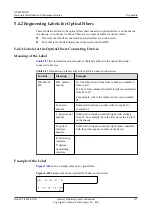
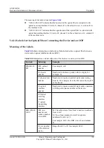
background image

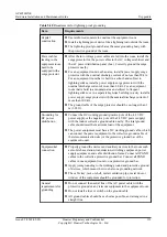
Item

Requirements

Grounding
resistance

l

The grounding resistance must be lower than 1 ohm.

l

The upper end of the grounding body should be at least 0.7 m (2.30
ft) over the ground. In cold areas, bury the grounding body below
the frozen ground.

l

Measure the grounding resistance periodically to ensure effective
grounding.

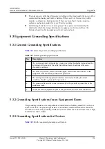
Routing of
signal cable

l

Do not arrange the signal cables overhead in the equipment room.
All signal cables must be led into the site underground.

l

Use the cables with a metal jacket or place them into a metal pipe if
they come out/in the equipment room.

l

Ground the idle lines inside the cable in the equipment room.

l

Signal cables should be deployed on internal walls. Do not deploy
outdoor aerial cables.

l

Keep signal cables away from power cables and surge protection
devices.

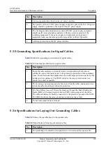
Collective
ground cable

l

Use a ground ring or ground bar for the collective ground cable.

l

Do not use aluminum cables as ground cables. Adopt measures to
prevent electrification corrosion when connecting different metal
parts together.

l

Use a copper busbar as the collective ground cable with a cross-
sectional area of no less than 120 mm

2

 (0.19 in.

2

), or use the

galvanized flat steel of the same resistance. Insulate the collective
ground cable from the reinforcing steel bars of the building.

Grounding lead-
in

The grounding lead-in should be a maximum of 30 m (98.42 ft) long.
Use the galvanized flat steel with cross-sectional area of 40 mm x 4
mm (1.58 in. x 0.158 in.) or 50 mm x 5 mm (1.97 in. x 0.197 in.).


5.2.2 Requirements for Power Supply

5.2.2.1 Requirements for AC Power Supply

An AC power supply system consists of power mains, uninterruptible power supplies (UPSs),
and self-supplied electric generators. In addition to meeting the requirements of the server
load, the AC power supply must have a simple connection line, safe operation, flexible
scheduling, and easy maintenance.

The low-voltage power supply should be 3-phase, 5-wire mode or monophase 3-wire mode.
This AC power supply should be 110 V/220 V, with a frequency of 50 Hz.

The UPS should supply the same power and operate at the same phase as the power mains.
The switching time between the UPS and mains should be less than 10 ms; otherwise, the
networking devices will reboot or reset.

For power distribution capacity in the equipment room, both the working current and fault
current of the devices should be considered. Ensure that independent AC power supplies

AP4050DN-E
Hardware Installation and Maintenance Guide

5 Appendix

Issue 05 (2018-02-02)

Huawei Proprietary and Confidential

Copyright © Huawei Technologies Co., Ltd.

123

Summary of Contents for AP4050DN-E

Page 1: ...AP4050DN E Hardware Installation and Maintenance Guide Issue 05 Date 2018 02 02 HUAWEI TECHNOLOGIES CO LTD ...

Page 2: ...cument may not be within the purchase scope or the usage scope Unless otherwise specified in the contract all statements information and recommendations in this document are provided AS IS without warranties guarantees or representations of any kind either express or implied The information in this document is subject to change without notice Every effort has been made in the preparation of this d...

Page 3: ...ion which if not avoided will result in death or serious injury Indicates a potentially hazardous situation which if not avoided could result in death or serious injury Indicates a potentially hazardous situation which if not avoided may result in minor or moderate injury Indicates a potentially hazardous situation which if not avoided could result in equipment damage data loss performance deterio...

Page 4: ...6 3 Installing the Device on a T rail l 2 6 4 Removing an AP Issue 04 2017 08 31 This version has the following updates The following information is modified l 1 1 Device Structure l 2 3 Unpacking the Equipment Issue 03 2017 01 20 This version has the following updates The following information is modified l 2 6 1 Installing the Device on a Wall l 2 6 2 Installing the Device on a Ceiling l 2 6 3 I...

Page 5: ... 2016 07 22 Initial commercial release AP4050DN E Hardware Installation and Maintenance Guide About This Document Issue 05 2018 02 02 Huawei Proprietary and Confidential Copyright Huawei Technologies Co Ltd iv ...

Page 6: ...6 4 Removing an AP 20 2 7 Cable Connection 20 2 8 Connecting the Security Lock 23 2 9 Checking the Device After Installation 23 2 10 Powering on the AP 24 3 Logging In to the Device 25 3 1 Logging In to the Device Using STelnet Telnet 25 3 2 Logging In to the Device Through the Web System 27 3 3 Logging In to the Device Through the Console Port 29 4 Hardware Failures 32 4 1 A Device Fails to Be Po...

Page 7: ...ng Cable Accessories 94 5 1 5 2 Installing Power Adapters 95 5 1 5 2 1 Installing the OT Terminal 95 5 1 5 2 2 Installing the Cord End Terminal 98 5 1 5 2 3 Installing a 2 Pin Round Connector and a DC Power Cable 99 5 1 5 3 Installing Ethernet Adapters 102 5 1 5 3 1 Installing a Shielded Ethernet Connector 103 5 1 5 3 2 Installing an Unshielded Ethernet Connector 104 5 1 5 4 Installing Fiber Conne...

Page 8: ...4 1 2 Type and Structure 130 5 4 1 3 Label Printing 131 5 4 1 4 Writing Labels 133 5 4 1 5 Attaching Labels 134 5 4 1 6 Contents of Engineering Labels 136 5 4 1 7 Precautions for Using Engineering Labels 136 5 4 2 Engineering Labels for Optical Fibers 137 5 4 2 1 Labels for the Optical Fibers Connecting Devices 137 5 4 2 2 Labels for the Optical Fibers Connecting the Device and an ODF 138 5 4 3 En...

Page 9: ... 802 11n ac WLANs for scenarios that can integrate enhanced applications such as Bluetooth and RFID such as shopping malls supermarkets healthcare warehouse manufacturing and logistics It provides flexible distribution options in different environments A cloud AP must be used together with a cloud server 1 1 Device Structure 1 2 Indicator Description 1 3 Basic Specifications 1 4 Ordering Informati...

Page 10: ... 3 seconds 2 USB port Connects to a USB flash drive to extend the storage space of the AP and provides a maximum of 2 5 W power 3 Console Connects to a maintenance terminal for AP configuration and management 4 GE1 PoE_OUT 10 100 1000M port connects to the wired Ethernet and supports PoE output AP4050DN E Hardware Installation and Maintenance Guide 1 Product Overview Issue 05 2018 02 02 Huawei Pro...

Page 11: ...therwise the AP may be damaged l For power adapter models see 5 9 Power Adaptation Solution 1 2 Indicator Description The AP4050DN E provides only a single indicator as shown in Figure 1 2 NOTE Indicator colors may vary slightly at different temperature Figure 1 2 Indicator Indicator Table 1 2 Description about the single indicator Type Color Status Description Default status after power on Green ...

Page 12: ...sts to go online if it works in Fit AP or cloud based management mode The indicator remains in this state before the AP successfully goes online l The AP works in Fit AP or cloud based management mode and fails to go online Fault Red Steady on A fault that affects services has occurred such as a DRAM detection failure or system software loading failure The fault cannot be automatically rectified a...

Page 13: ...es 300 m Storage temperature 40 C to 70 C Operating humidity 5 to 95 non condensing IP rating IP41 Atmospheric pressure 53 kPa to 106 kPa 1 4 Ordering Information To place an order contact technical support personnel Part Number Description 50082944 AP4050DN E Mainframe 11ac wave2 Dual Band Built in Antenna BT USB PSE IoT Slot 50083055 AP4050DN E Mainframe Bundle AP4050DN E Mainframe 8 AP4050DN E ...

Page 14: ... 1 Preparing for Installation This section describes safety precautions and tool preparations for AP installation Safety Precautions l Take proper measures to prevent injuries and device damage l Place the device in a dry and flat position away from any liquid and prevent the device from slipping l Keep the device clean l Do not put the device and tools in the aisles AP4050DN E Hardware Installati...

Page 15: ...ls listed in Table 2 1 Table 2 1 Tools Phillips screwdriver Protective gloves ESD gloves Slip proof glove Marker Hammer drill Claw hammer Diagonal pliers Wire stripper RJ45 crimping tool Cable cutter Network cable tester Multimeter Ladder Safety helmet AP4050DN E Hardware Installation and Maintenance Guide 2 AP Installation Issue 05 2018 02 02 Huawei Proprietary and Confidential Copyright Huawei T...

Page 16: ...carton is intact and not damaged or soaked Stop unpacking if the equipment is rusted or soggy Then investigate causes and contact the supplier After unpacking check items in the carton against the packing list If any item is missing contact the supplier or agent AP4050DN E Hardware Installation and Maintenance Guide 2 AP Installation Issue 05 2018 02 02 Huawei Proprietary and Confidential Copyrigh...

Page 17: ...ll or ceiling using sheet metal mounting brackets The installation position is determined by the site survey There must be at least 200 mm clearance between the cabling end of the AP and the wall Figure 2 2 shows space requirements Figure 2 2 Mounting an AP 200 mm 200 mm 200 mm 200 mm Floor Celling Wall When determining the AP installation position comply with the following rules l Try to reduce t...

Page 18: ...ent Indoor installation l There should be at least a 7 m distance between antennas l The antennas should be placed at least 5 m from the 4G antennas of the carrier l The antennas should be placed far away from electronic devices that may produce interference such as microwave ovens NOTE If antennas are embedded into APs the deployment distance requirements on the antennas are those on APs 2 5 Inst...

Page 19: ... IoT cards in the slots and tighten the cards using M2x7 screws with a tightening torque of 1 5 N m You are advised to start installation from the card1 slot AP4050DN E Hardware Installation and Maintenance Guide 2 AP Installation Issue 05 2018 02 02 Huawei Proprietary and Confidential Copyright Huawei Technologies Co Ltd 11 ...

Page 20: ...than or equal to 8 mm otherwise the cable cannot be installed 5 Slide the cover back Two Cable per Card In this mode only one RFID card can be installed The card1 slot is preferentially used 1 Remove the front cover of an AP AP4050DN E Hardware Installation and Maintenance Guide 2 AP Installation Issue 05 2018 02 02 Huawei Proprietary and Confidential Copyright Huawei Technologies Co Ltd 12 ...

Page 21: ...in the card1 slot and tighten the card using M2x7 screws with a tightening torque of 1 5 N m AP4050DN E Hardware Installation and Maintenance Guide 2 AP Installation Issue 05 2018 02 02 Huawei Proprietary and Confidential Copyright Huawei Technologies Co Ltd 13 ...

Page 22: ...al to 8 mm otherwise the cable cannot be installed 5 Slide the cover back 2 6 Installing the AP NOTE Remove the protective film on the surface before installation to prevent electrostatic discharge 2 6 1 Installing the Device on a Wall AP4050DN E Hardware Installation and Maintenance Guide 2 AP Installation Issue 05 2018 02 02 Huawei Proprietary and Confidential Copyright Huawei Technologies Co Lt...

Page 23: ...at the arrows point upwards on the label 1 Fix a mounting bracket to the wall against the wall and mark the drilling positions through holes of the bracket 59 mm 85 mm 2 Use a 6 mm drill bit to drill 25 mm to 30 mm deep holes in the drilling positions Hammer the expansion tubes into the holes until the expansion tubes are completely embedded into the wall 25 mm 30 mm Ø6 3 Fix the mounting bracket ...

Page 24: ...n the mounting bracket and vertically push the AP to secure it When the spring clip is popped up push the AP downward until it snaps into place you can hear a click a b AP4050DN E Hardware Installation and Maintenance Guide 2 AP Installation Issue 05 2018 02 02 Huawei Proprietary and Confidential Copyright Huawei Technologies Co Ltd 16 ...

Page 25: ...ting holes based on the distance between two installation holes on the mounting bracket use a hammer drill to drill holes on the ceiling tile and fix the mounting bracket to the ceiling tile with a tightening torque of 1 4 N m The screws provided for ceiling mounting of APs are 30 mm long and can be used to fix an AP on a ceiling no thicker than 15 mm To install APs on thicker ceilings you need to...

Page 26: ...ibrations tighten the AP to the mounting bracket using M4x30 screws with a torque of 1 4N m This prevents the AP falling off from due to vibrations In normal scenarios you do not need to install these screws 2 6 3 Installing the Device on a T rail A T rail needs to bear the weight of four times the total weight of the device and mounting bracket without damage Figure 2 3 shows the T rail dimension...

Page 27: ...Sheet metal mounting bracket 2 Connect the cables For details see 2 7 Cable Connection 3 Align the rubber feet of the device over the mounting slots on the mounting bracket and vertically push the AP to secure it When the spring clip is popped up push the AP horizontally until it snaps into place you can hear a click b c a AP4050DN E Hardware Installation and Maintenance Guide 2 AP Installation Is...

Page 28: ...rios you do not need to install these screws 2 6 4 Removing an AP Flip the spring clip on the mounting bracket and slip the AP towards the spring clip Release the spring clip until the rubber feet of the AP enter the mounting keyholes Remove the AP from the mounting bracket Figure 2 4 Removing an AP a b c NOTE If a captive screw is installed remove the screw and then follow the preceding steps to ...

Page 29: ...ription 1 USB flash drive Connects to a USB flash drive to extend the storage space of the AP and provides a maximum of 2 5 W power AP4050DN E Hardware Installation and Maintenance Guide 2 AP Installation Issue 05 2018 02 02 Huawei Proprietary and Confidential Copyright Huawei Technologies Co Ltd 21 ...

Page 30: ...t power is 7 W when no IoT card is connected to the AP and the USB port is not used l The maximum output power is 5 5 W when only one IoT card is connected to the AP and the USB port is not used l The PoE_OUT function is automatically disabled when two or more IoT cards are connected to the AP or the USB port is used 3 DC power adapter When the AP uses the DC power supply use a power adapter for p...

Page 31: ... the security slot and lock it Lock hole Security lock NOTE You need to purchase the security lock separately 2 9 Checking the Device After Installation Table 2 4 shows the items to be checked after installation is complete For more details see Installation Checklist in the appendix Table 2 4 Installation checklist No Check Item 1 The device is installed by strictly following the design draft The ...

Page 32: ...complete intact and tightly connected The signal cables are not damaged or broken 8 Labels on cables are clear and correct 2 10 Powering on the AP After the AP is powered on observe the indicator on the AP to check the system running status For details see 1 2 Indicator Description NOTE Do not frequently power on and off the device AP4050DN E Hardware Installation and Maintenance Guide 2 AP Instal...

Page 33: ...and wireless connections l In versions earlier than V200R007C20 APs support wired connections l In V200R007C20 and later Fat APs support both wired and wireless connections and Fit APs and cloud APs support wired connections Before logging in to the device complete the following tasks l Power on the device l Prepare network cables used to connect device interfaces for wired connections No network ...

Page 34: ...in to the AP using STelnet for operations l If the cloud AP is offline or does not go online you can access the device through the offline management VAP for operations By default the SSID of the offline management VAP is hw_manage_xxxx xxxx specifies the last four bits of the AP s MAC address and the password is hw_manage After the PC dynamically obtains an IP address and connects to the AP you c...

Page 35: ...e documentation of the correct version Configuration Search for Fat AP product documentation and refer to the configuration guide in the documentation of the correct version l cloud AP Upgrade Search for cloud AP upgrade guide and refer to the upgrade guide in the documentation of the correct version Online configuration Search for cloud AP product documentation and refer to the configuration guid...

Page 36: ...ine management VAP is hw_manage_xxxx xxxx specifies the last four bits of the AP s MAC address and the password is hw_manage After the IP address of the PC is set to 169 254 2 x 24 169 254 2 1 excluded and 169 254 2 100 recommended the connection is set up and you can log in to the AP using web system for operations l If the cloud AP is offline or does not go online you can access the device throu...

Page 37: ...rise and search for product documentation by keyword The search method is described as follows l Fit AP Upgrade Search for Fit AP upgrade guide and refer to the upgrade guide in the documentation of the correct version Configuration Search for AC6605 product documentation and refer to the configuration guide in the documentation of the correct version l Fat AP Upgrade Search for Fat AP upgrade gui...

Page 38: ...cation Username admin Password Info You are advised to change the password to ensure security For a Fat AP and Cloud AP set a passowrd of console and use the password to log in Please configure the login password Info A plain text password is a string of 8 to 16 case sensitive characters and must be a combination of at least two of the follow ing uppercase letters A to Z lowercase letters a to z d...

Page 39: ...de in the documentation of the correct version Online configuration Search for cloud AP product documentation and refer to the configuration guide in the documentation of the correct version Service configuration after APs go online Search for CloudCampus solution product documentation and refer to the deployment guide in the documentation of the correct version AP4050DN E Hardware Installation an...

Page 40: ...ble Cause Power supply using a power module l The device is powered off l The power cable is not securely connected to the device l The power supply unit has failed If the device connects to an external power source its power adapter may fail If the device has a built in power supply the device itself may be faulty AP4050DN E Hardware Installation and Maintenance Guide 4 Hardware Failures Issue 05...

Page 41: ...e Troubleshooting Procedure Power supply using a power module 1 Check whether the device is powered off 2 Check that the power cable is securely connected to the device 3 Check whether the power supply is normal Replace the power adapter with a normal one If the device is powered on the original power adapter is faulty Contact technical support personnel or Huawei agent and ask them to replace the...

Page 42: ...supply errors such as the PoE function is disabled or the power off time range is incorrectly set 5 Check whether the network cable or distribution frame is faulty 6 If the device still cannot be powered on the device itself is faulty Contact technical support personnel or Huawei agent and ask them to replace the device NOTE The output power of an 802 3af PSE port is 15 4 W that of an 802 3at PSE ...

Page 43: ... Cables l If the cable jacket or insulation is visibly dirty clean it before assembly l If the jacket or insulation of a cable has visible damage irreparable scuffing or other defects do not use the cable l If the shield layer of a cable is damaged do not use the cable l If the cable jacket or insulation cracks after the cable is bent or twisted discard this cable and check whether other cables ha...

Page 44: ... braid or aluminum foil insulation core conductors and other jackets that do not need to be stripped After assembling cables cut all visible cross sections of jackets to ensure that the cross sections are arranged neatly Do not touch the core conductors of cables with your hands Terminate exposed conductors in a timely way after stripping off insulation so that the surface of the conductors does n...

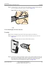
Page 45: ...ie separate the socket and nut and install them on the cable as shown in Figure 5 2 Figure 5 2 Installing the nut on the cable Step 2 Strip the cable as shown in Figure 5 3 AP4050DN E Hardware Installation and Maintenance Guide 5 Appendix Issue 05 2018 02 02 Huawei Proprietary and Confidential Copyright Huawei Technologies Co Ltd 37 ...

Page 46: ...5 4 Inserting core wires Step 4 Use a Phillips screwdriver to tighten the crimping screw in hole rotate the connector by 180 degree and tighten the crimping screw in hole as shown in Figure 5 5 AP4050DN E Hardware Installation and Maintenance Guide 5 Appendix Issue 05 2018 02 02 Huawei Proprietary and Confidential Copyright Huawei Technologies Co Ltd 38 ...

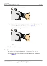
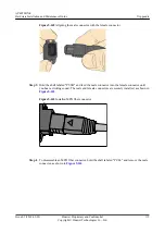
Page 47: ...er to tighten the socket with the tightening torque no less than 1 2 N m as shown in Figure 5 7 Figure 5 7 Tightening the socket Step 7 Pre tighten the socket and nut and use the Phillips screwdriver to tighten the nut with the tightening torque no less than 1 2 N m as shown in Figure 5 8 AP4050DN E Hardware Installation and Maintenance Guide 5 Appendix Issue 05 2018 02 02 Huawei Proprietary and C...

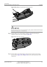
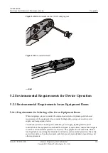
Page 48: ...l The cable shield layer is properly connected to the metal enclosure l Core wires are properly connected to the connector s holes Step 9 If devices are installed outdoor wrap three layers of PVC insulation tape around the connector for protection as shown in Figure 5 10 NOTICE Ensure that proper quantity of the PVC insulation tape is used for wrapping the connector facilitating the connector unin...

Page 49: ...Cable Commonly Used Colors Colors Used in Britain DC round waterproof connector RTN Black or brown Blue NEG Blue Gray NOTE The color and appearance of cables in this topic are for reference only The cable color and appearance vary depending on countries and regions Figure 5 11 shows components of the DC round waterproof connector AP4050DN E Hardware Installation and Maintenance Guide 5 Appendix Is...

Page 50: ...ing jaw boss to the groove inside the socket and ensure that the clamping jaw is completely installed in the socket as shown in Figure 5 13 NOTE l Power cables supported by clamping jaw 1 2 x 12 AWG 2 x 4 mm2 and 2 x 6 mm2 l Power cables supported by clamping jaw 2 2 x 8 AWG and 2 x 10 mm2 Figure 5 12 Replacing clamping jaws 1 Clamping jaw 1 2 Clamping jaw 2 AP4050DN E Hardware Installation and Ma...

Page 51: ... outer jacket 48 mm on the head of the cable to be connected and the outer jacket 17 mm of each core wire twist the shield layers into one strand as shown in Figure 5 15 NOTICE l The stripping ruler card is delivered with the components of the connector l Cut the padding using diagonal pliers l Gently strip the insulation sheath to avoid damage to the conductor metal l Ensure that the edge of core...

Page 52: ...e cables are assembled pull the cables slightly to check whether the connections are secure If the cable slides outward or the wire of the cable is exposed outside the hole for the cable remove the cable cut the split wires and then strip the jacket and install the cable again Step 6 Twist the shield layers into one strand and insert it into the shield slot tighten the tail screw and fasten the sh...

Page 53: ...cket is invisible as shown in Figure 5 18 Figure 5 18 Tightening the socket and enclosure Step 8 Pre tighten the nut and socket and further tighten the nut using a torque wrench opening width 28 mm as shown in Figure 5 19 AP4050DN E Hardware Installation and Maintenance Guide 5 Appendix Issue 05 2018 02 02 Huawei Proprietary and Confidential Copyright Huawei Technologies Co Ltd 45 ...

Page 54: ... holes of the connector l Ensure that the short circuit does not occur between the metal enclosure and connector s positive and negative holes Step 10 If devices are installed outdoor wrap three layers of PVC insulation tape around the connector for protection as shown in Figure 5 21 AP4050DN E Hardware Installation and Maintenance Guide 5 Appendix Issue 05 2018 02 02 Huawei Proprietary and Confid...

Page 55: ...ting the connector uninstallation in later maintenance End 5 1 2 3 Assembling the OT Terminal and Power Cable Context Figure 5 22 shows the components of an OT terminal and a power cable AP4050DN E Hardware Installation and Maintenance Guide 5 Appendix Issue 05 2018 02 02 Huawei Proprietary and Confidential Copyright Huawei Technologies Co Ltd 47 ...

Page 56: ...wn in Figure 5 23 The recommended values of L1 are listed in Table 5 2 Figure 5 23 Stripping a power cable OT terminal NOTICE l When you strip a power cable do not damage the conductor of the cable l If the bare crimping terminal is not provided by Huawei the value of L1 is 1 mm 0 04 in to 2 mm 0 08 in greater than the value of L AP4050DN E Hardware Installation and Maintenance Guide 5 Appendix Is...

Page 57: ...g the part to be crimped with the power cable Step 2 Put the heat shrinkable A tubing onto the bare crimping terminal as shown in Figure 5 24 Figure 5 24 Putting the heat shrink tubing onto the bare crimping terminal Step 3 Put the OT terminal B onto the exposed conductor and ensure that the OT terminal is in good contact with the insulation coating C as shown in Figure 5 24 NOTICE After the condu...

Page 58: ...connector until the tube covers the crimped part and then use a heat gun to heat the tube as shown in Figure 5 26 Figure 5 26 Heating the heat shrink tubing OT terminal NOTICE Stop heating the shrink tubing when the connector is securely locked in the shrink tubing Do not heat the shrink tubing too long as this may damage the insulation coating End AP4050DN E Hardware Installation and Maintenance ...

Page 59: ...e insulation to expose the cable conductor with a length of L as shown in Figure 5 28 The recommended values of L are listed in Table 5 3 NOTICE l When you strip a power cable do not damage the conductor of the cable l If the bare crimping terminal is not provided by Huawei you can adjust the value of L as required Figure 5 28 Stripping a power cable JG terminal AP4050DN E Hardware Installation an...

Page 60: ...imping terminal Step 3 Put the bare crimping terminal onto the exposed conductor and ensure that the bare crimping terminal is in good contact with the insulation of the power cable as shown in Figure 5 29 Step 4 Crimp the joint parts of the bare crimping terminal and the conductor as shown in Figure 5 30 Figure 5 30 Crimping the joint parts of the bare crimping terminal and the conductor JG termi...

Page 61: ... a cord end terminal and a power cable Figure 5 32 Components of a cord end terminal and a power cable A Cord end terminal B Insulation layer of a power cable C Conductor of a power cable Procedure Step 1 Strip a part of the insulation to expose the cable conductor with a length of L1 as shown in Figure 5 33 The recommended values of L1 are listed in Table 5 4 AP4050DN E Hardware Installation and ...

Page 62: ...02 10 0 39 16 0 025 15 0 59 2 5 0 004 10 0 39 25 0 039 18 0 71 4 0 006 12 0 47 35 0 054 19 0 75 6 0 009 14 0 55 50 0 077 26 1 02 Step 2 Put the cord end terminal onto the conductor and ensure that the conductor is aligned with the edge of the cord end terminal as shown in Figure 5 34 NOTICE After the conductor is fed into the cord end terminal the protruding part of the conductor must not be longe...

Page 63: ...idth of a tubular crimped terminal is listed in Table 5 5 Table 5 5 Maximum width of a tubular crimped terminal Cross Sectional Area of Tubular Terminal mm2 in 2 Maximum Width of Crimped Terminal W1 mm in 0 25 0 0004 1 0 04 0 5 0 0008 1 0 04 1 0 0 0015 1 5 0 06 1 5 0 0023 1 5 0 06 2 5 0 0039 2 4 0 09 4 0 006 3 1 0 12 6 0 009 4 0 16 AP4050DN E Hardware Installation and Maintenance Guide 5 Appendix ...

Page 64: ...onnector and a shielded Ethernet cable Figure 5 36 Shielded RJ45 connector and cable A Jacket of connector B Metal shell of connector C Wire holder of connector D Plug of connector E Jacket of Ethernet cable F Shield layer of Ethernet cable G Twisted pair wires Procedure Step 1 Fit the jacket of the connector onto the Ethernet cable as shown in Figure 5 37 AP4050DN E Hardware Installation and Main...

Page 65: ...do not damage the shield layer of the twisted pair cable l When you remove the shield layer do not damage the insulation of the twisted pair cable Figure 5 38 Removing the jacket of a twisted pair cable unit mm in Step 3 Fit the metal shell onto the twisted pair cable The shield layer is covered by the metal shell as shown in Figure 5 39 AP4050DN E Hardware Installation and Maintenance Guide 5 App...

Page 66: ...about 20 mm 0 79 in long as shown in Figure 5 40 Figure 5 40 Removing the shield layer of a twisted pair cable unit mm in Step 5 Lead the four pairs of twisted pair wires through the wire holder as shown in Figure 5 41 and Figure 5 42 Ensure that the colored wires are in the correct location in the cable Figure 5 41 Leading wires through the wire holder C G AP4050DN E Hardware Installation and Mai...

Page 67: ...n the wires and the pins are shown in Figure 5 44 and listed in Table 5 6 Figure 5 43 Four pairs of cables on a wire holder Figure 5 44 Connections between wires and pins Brown White Brown Green White Blue Blue White Green Orange White Orange Pin 8 Pin 1 AP4050DN E Hardware Installation and Maintenance Guide 5 Appendix Issue 05 2018 02 02 Huawei Proprietary and Confidential Copyright Huawei Techno...

Page 68: ... along the lower edge of the wire holder as shown in Figure 5 45 Figure 5 45 Cutting off surplus cables Step 8 Put the connector body onto the wire holder and turn the metal shell by 90 as shown in Figure 5 46 NOTE Ensure that the wire holder is in good contact with the connector body AP4050DN E Hardware Installation and Maintenance Guide 5 Appendix Issue 05 2018 02 02 Huawei Proprietary and Confi...

Page 69: ...own in Figure 5 47 Figure 5 47 Crimping the connector Step 10 Push the jacket towards the metal shell until the metal shell is covered This completes the assembly of one end of the cable as shown in Figure 5 48 Figure 5 48 Pushing the metal shell AP4050DN E Hardware Installation and Maintenance Guide 5 Appendix Issue 05 2018 02 02 Huawei Proprietary and Confidential Copyright Huawei Technologies C...

Page 70: ...cket Such a connector can be used for crimping CAT 6 network cables Figure 5 49 shows the shielded RJ45 connector Figure 5 49 Shielded RJ45 connector 1 Core wires 2 Aluminum foil 3 Braid shield 4 Outer jacket 5 RJ45 connector 6 Load bar 7 Cable support rack Procedure Step 1 Strip 20 mm outer jacket off the network cable peel off the braid shield backward and cut off the aluminum foil and protectio...

Page 71: ... shown in Figure 5 51 and fix the cable support rack to the bottom of the core wires Figure 5 51 Core wire order Step 3 Hold the arranged core wires and route them through the load bar as shown in Figure 5 52 Table 5 7 shows the mapping between the core wires and pins of the connector AP4050DN E Hardware Installation and Maintenance Guide 5 Appendix Issue 05 2018 02 02 Huawei Proprietary and Confi...

Page 72: ...te blue 6 Green 7 White brown 8 Brown Step 4 After routing core wires through the load bar move the load bar to the bottom to connect to the cable support rack and neatly cut the edge cables as shown in Figure 5 53 AP4050DN E Hardware Installation and Maintenance Guide 5 Appendix Issue 05 2018 02 02 Huawei Proprietary and Confidential Copyright Huawei Technologies Co Ltd 64 ...

Page 73: ...be checked on the side or front end face of the connector Step 6 Use the crimping tool to crimp the connector as shown in Figure 5 55 Use cutting pliers to neatly cut braid shields exposed out of the connector along the load bar as shown in Figure 5 56 Figure 5 55 Crimping the connector AP4050DN E Hardware Installation and Maintenance Guide 5 Appendix Issue 05 2018 02 02 Huawei Proprietary and Con...

Page 74: ...ontext This topic describes how to assemble an integrated shielded RJ45 connector with a Secure File Transfer Protocol SFTP straight through network cable as an example The connector does not have a cable support rack or metal jacket Figure 5 57 shows the integrated shielded RJ45 connector AP4050DN E Hardware Installation and Maintenance Guide 5 Appendix Issue 05 2018 02 02 Huawei Proprietary and ...

Page 75: ...f the aluminum foil and protection band as shown in Figure 5 58 NOTICE Ensure that the shielded layer is intact when stripping outer jackets off the network cable Keep the cable insulation intact when stripping the shielded layer Figure 5 58 Stripping the cable AP4050DN E Hardware Installation and Maintenance Guide 5 Appendix Issue 05 2018 02 02 Huawei Proprietary and Confidential Copyright Huawei...

Page 76: ...8 Mapping between core wires and pins Pin ID Core Wire Color 1 White orange 2 Orange 3 White green 4 Blue 5 White blue 6 Green 7 White brown 8 Brown Step 3 Route the arranged core wires through the RJ45 connector as shown in Figure 5 60 AP4050DN E Hardware Installation and Maintenance Guide 5 Appendix Issue 05 2018 02 02 Huawei Proprietary and Confidential Copyright Huawei Technologies Co Ltd 68 ...

Page 77: ...osed out of the connector along the load bar as shown in Figure 5 62 Figure 5 62 Neatly cutting braid shields Step 6 Repeat Step 1 through Step 5 to assemble the integrated shielded RJ45 connector on the other end of the network cable End AP4050DN E Hardware Installation and Maintenance Guide 5 Appendix Issue 05 2018 02 02 Huawei Proprietary and Confidential Copyright Huawei Technologies Co Ltd 69...

Page 78: ... Connector jacket Figure 5 64 Shielded RJ45 connector Figure 5 65 Cable A Connector jacket B Connector C Core wires of the twisted pair D Aluminum foil used as the network cable shield E Network cable jacket Procedure Step 1 Route the network cable through the connector jacket as shown in Figure 5 66 AP4050DN E Hardware Installation and Maintenance Guide 5 Appendix Issue 05 2018 02 02 Huawei Propr...

Page 79: ...elded layer is intact when stripping outer jackets off the twisted pair cable Figure 5 67 Stripping the outer jacket Step 3 Pull outward the shielded aluminum foil and cut off the PET membrane and ground cables along the end face of the outer jacket as shown in Figure 5 68 AP4050DN E Hardware Installation and Maintenance Guide 5 Appendix Issue 05 2018 02 02 Huawei Proprietary and Confidential Copy...

Page 80: ...ng pliers to neatly cut the front end of the twisted pair as shown in Figure 5 70 Figure 5 71 shows pin arrangement of each contact of the connector Figure 5 69 Mapping between colors and pins AP4050DN E Hardware Installation and Maintenance Guide 5 Appendix Issue 05 2018 02 02 Huawei Proprietary and Confidential Copyright Huawei Technologies Co Ltd 72 ...

Page 81: ...tor as shown in Figure 5 72 NOTICE l Cables must be inserted into the bottom l The aluminum foil must keep intact after cables are inserted into the connector Figure 5 72 Inserting cables into the connector AP4050DN E Hardware Installation and Maintenance Guide 5 Appendix Issue 05 2018 02 02 Huawei Proprietary and Confidential Copyright Huawei Technologies Co Ltd 73 ...

Page 82: ...the connector as shown in Figure 5 73 Figure 5 73 Crimping the connector Step 7 Move the connector jacket to the connector body to wrap the connector shell as shown in Figure 5 74 AP4050DN E Hardware Installation and Maintenance Guide 5 Appendix Issue 05 2018 02 02 Huawei Proprietary and Confidential Copyright Huawei Technologies Co Ltd 74 ...

Page 83: ...5 Connector and Ethernet Cable Context Figure 5 75 shows the components of an unshielded RJ45 connector and cable Figure 5 75 Components of an unshielded RJ45 connector and cable A B C A Plug of connector B Jacket C Twisted pair wires AP4050DN E Hardware Installation and Maintenance Guide 5 Appendix Issue 05 2018 02 02 Huawei Proprietary and Confidential Copyright Huawei Technologies Co Ltd 75 ...

Page 84: ...n the wires and the pins are listed in Table 5 9 Figure 5 77 Connections between wires and pins unit mm in C 16 White Orange White Green Orange Blue White Blue Green White Brown Brown Pin 8 Pin 1 Table 5 9 Connections between wires and pins using a straight through cable as an example Matching Pins of Wires Wire Color 1 White Orange 2 Orange 3 White Green 4 Blue 5 White Blue 6 Green 7 White Brown ...

Page 85: ... an offset of less than 10 l To ensure conductivity the surface of the contact strips must be clean l The contact strips must be in good contact with the RJ45 socket The plastic separators must remain intact and be aligned l The contact strip blade must extend beyond the ends of the wires The ends of the wires must be in contact with the edge of the RJ45 The distance between them must be less than...

Page 86: ... 2 Hold an RJ45 connector and turn it 45 Observe the top edges of the metal contact strips Figure 5 81 shows an unqualified piece Figure 5 81 Unparallel contact strips of different heights AP4050DN E Hardware Installation and Maintenance Guide 5 Appendix Issue 05 2018 02 02 Huawei Proprietary and Confidential Copyright Huawei Technologies Co Ltd 78 ...

Page 87: ... Figure 5 83 Skewed plastic separators Step 5 Hold the connector with the side facing towards you and check whether you can see the cross sections of the wires Ensure that the ends of the wires are in good contact with the edge of the RJ45 and that the contact strip blade extends beyond the ends of the wires and is crimped with the wires If not replace the connector Figure 5 84 shows an unqualifie...

Page 88: ...d 1 1 Orange White 6 6 Green Twisted 3 3 Green White 4 4 Blue Twisted 5 5 Blue White 8 8 Brown Twisted 7 7 Brown White l Crossover cables are connected in a crossover manner They are used to connect terminals such as two computers or switches Table 5 11 lists the connections of core wires in a crossover cable Table 5 11 Connections of core wires in a straight crossover cable RJ45 Connector 1 RJ45 ...

Page 89: ...e pins work normally and the wires are correctly connected NOTE Turn the switch to the S position to slow down lighting of the indicators so that you can see the indicators more clearly as shown in Figure 5 86 Figure 5 86 Testing the conduction and connections of wires Step 3 Gently shake the connector and repeat Step 2 to check whether the metal contact strips are in good contact with the core wi...

Page 90: ...the tester the indicators turn on in the sequence of 1 8 G At the slave right section of the tester the indicators turn on in the sequence of 3 6 1 4 5 2 7 8 G If the indicators do not come on in this sequence the Ethernet cable is unqualified NOTE If a tester is not available you can use a multimeter to perform a simple test as shown in Figure 5 88 Figure 5 88 Testing the connection of an Etherne...

Page 91: ... a standard go no go gauge to test the connectors purchased from other suppliers Replace the connectors if they do not comply with the standard Wires in a network cable are connected to wrong pins After a network cable is made use a conduction tester to measure cable connectivity For test details see 5 1 3 7 Testing the Connection of Assembled Cables A network cable connector is not crimped secure...

Page 92: ...n 25 5 W 12 5 ohms If an AP is connected to a switch or AC excluding ACU2 you can run the virtual cable test command on the switch or AC to check network cable connectivity For details see the virtual cable test command in the command reference 5 1 4 Assembling Feeders 5 1 4 1 Assembling the Straight Male Coaxial N Connector and the 1 2 Feeder Context Figure 5 89 shows the components of an N coaxi...

Page 93: ...Ensure that the feeder cable is cut at the wave crest of the outer conductor l The inner conductor must be beveled as shown in Figure 5 90 Step 2 Use a brush to remove the dirt on the cross section of the feeder cable Step 3 Feed the feeder cable into the heat shrink tubing and cover the outer conductor of the feeder cable with the O ring seal as shown in Figure 5 91 AP4050DN E Hardware Installati...

Page 94: ...of the connector onto the feeder cable Step 5 Mount the body of the connector onto the feeder cable so that the inner conductors of the connector and feeder cable are connected Use a spanner 27 N m to 30 N m torque recommended to fasten the body and back shell as shown in Figure 5 93 AP4050DN E Hardware Installation and Maintenance Guide 5 Appendix Issue 05 2018 02 02 Huawei Proprietary and Confid...

Page 95: ... Figure 5 94 Then heat the tube Figure 5 94 Assembled N connector Step 7 After the components are assembled install the connector as shown in Figure 5 95 AP4050DN E Hardware Installation and Maintenance Guide 5 Appendix Issue 05 2018 02 02 Huawei Proprietary and Confidential Copyright Huawei Technologies Co Ltd 87 ...

Page 96: ... Male Coaxial N Connector and an RG8U Feeder Context Figure 5 96 shows the coaxial N connector and RG8U feeder AP4050DN E Hardware Installation and Maintenance Guide 5 Appendix Issue 05 2018 02 02 Huawei Proprietary and Confidential Copyright Huawei Technologies Co Ltd 88 ...

Page 97: ...nsulation medium of the feeder I Internal conductor of the feeder Procedure Step 1 Strip the feeder with the length shown in Figure 5 97 NOTICE Ensure that the shielded layer F is intact after the stripping AP4050DN E Hardware Installation and Maintenance Guide 5 Appendix Issue 05 2018 02 02 Huawei Proprietary and Confidential Copyright Huawei Technologies Co Ltd 89 ...

Page 98: ... clip until the clip is close to the Cable jacket as shown in Figure 5 99 Figure 5 99 Installing the clip Step 4 Peel off the shielded layer F to the direction of the clip C so that the aluminum foil G is exposed as shown in Figure 5 100 AP4050DN E Hardware Installation and Maintenance Guide 5 Appendix Issue 05 2018 02 02 Huawei Proprietary and Confidential Copyright Huawei Technologies Co Ltd 90 ...

Page 99: ...g the end face of the lining B Ensure that the length of the conducting line inside the feeder is 4 5 mm as shown in Figure 5 102 Figure 5 102 Cutting off the aluminum foil and insulation medium of the feeder Step 7 Use the file to taper the internal conductor I of the feeder as shown in Figure 5 103 AP4050DN E Hardware Installation and Maintenance Guide 5 Appendix Issue 05 2018 02 02 Huawei Propr...

Page 100: ...5 104 Clearing impurities Step 9 Insert the half finished part into the main body of the connector A and rotate the nut D and the connector s main body until you cannot rotate further as shown in Figure 5 105 AP4050DN E Hardware Installation and Maintenance Guide 5 Appendix Issue 05 2018 02 02 Huawei Proprietary and Confidential Copyright Huawei Technologies Co Ltd 92 ...

Page 101: ...re 5 106 Figure 5 106 Fixing the nut to the connector shell body Step 11 Figure 5 107 shows the effect drawing after the assembling is complete Figure 5 107 Effect drawing of the straight male coaxial N connector AP4050DN E Hardware Installation and Maintenance Guide 5 Appendix Issue 05 2018 02 02 Huawei Proprietary and Confidential Copyright Huawei Technologies Co Ltd 93 ...

Page 102: ...r of a cable or fiber Precautions for Installation l Hold terminals of cables instead of pulling the cables themselves when installing or removing cable components l Do not insert a connector forcibly when the connector is blocked Use a dedicated tool to pull out the connector Install the connector again after you check that the pins are inserted properly l Before tightening screws on cable connec...

Page 103: ...ep cables away from moveable components such as doors l Sharp objects must not touch cable wiring to prevent damage to cables l To protect power cables route power cables of the active and standby power modules separately 5 1 5 2 Installing Power Adapters 5 1 5 2 1 Installing the OT Terminal Procedure l Install an OT terminal a Align the hole of the OT terminal conductor upward with a connecting h...

Page 104: ...110 Figure 5 110 Installing two terminals back to back NOTICE Ensure that the OT terminal is not in contact with other terminals or metal components c Move the cable slightly and ensure that it is securely connected as shown in Figure 5 111 AP4050DN E Hardware Installation and Maintenance Guide 5 Appendix Issue 05 2018 02 02 Huawei Proprietary and Confidential Copyright Huawei Technologies Co Ltd ...

Page 105: ...T terminals can be installed using any of these methods Bend the upper OT terminal at a 45 or 90 degree angle as shown in Figure 5 112 Cross the two terminals as shown in Figure 5 113 Figure 5 112 Bending the upper OT terminal at a 45 or 90 degree angle Figure 5 113 Crossing two terminals AP4050DN E Hardware Installation and Maintenance Guide 5 Appendix Issue 05 2018 02 02 Huawei Proprietary and C...

Page 106: ...minal jack as shown in Figure 5 114 To ensure bump contact and dense connection place the plain side of the terminal outwards Figure 5 114 Placing a terminal on a terminal jack vertically Step 2 Insert the terminal into the jack vertically and turn the screw clockwise to fasten the terminal as shown in Figure 5 115 Figure 5 115 Feeding the terminal into the jack AP4050DN E Hardware Installation an...

Page 107: ...Round Connector and a DC Power Cable This topic describes how to install a 2 pin round connector and a DC power cable and related notes Context Figure 5 116 shows the 2 pin round connector with a DC power cable Figure 5 116 2 pin round connector and a DC power cable Procedure Step 1 Waterproof cables to be connected 1 Wrap a layer of PVC tape as shown in Figure 5 117 Figure 5 117 Wrapping the PVC ...

Page 108: ...119 Waterproof insulation tape 3 Wrap three layers of the PVC tape around the waterproof insulation tape as shown in Figure 5 120 Figure 5 120 Wrapping three layers of the PVC tape AP4050DN E Hardware Installation and Maintenance Guide 5 Appendix Issue 05 2018 02 02 Huawei Proprietary and Confidential Copyright Huawei Technologies Co Ltd 100 ...

Page 109: ...ape Step 2 Fix the DC power cable connector to the PWR port as shown in Figure 5 122 Ensure that positive and negative polarities are correct during the installation AP4050DN E Hardware Installation and Maintenance Guide 5 Appendix Issue 05 2018 02 02 Huawei Proprietary and Confidential Copyright Huawei Technologies Co Ltd 101 ...

Page 110: ...bearing preventing the DC power cable connector from being pulled Reserve the proper cable length between the binding point and the PWR port End 5 1 5 3 Installing Ethernet Adapters AP4050DN E Hardware Installation and Maintenance Guide 5 Appendix Issue 05 2018 02 02 Huawei Proprietary and Confidential Copyright Huawei Technologies Co Ltd 102 ...

Page 111: ...n Figure 5 124 Figure 5 124 Feeding the male shielded connector into the female shielded connector Step 3 When you hear a click the cable connector is completely inserted in the port The clip on the cable connector pops up to fix the connector in the port Pull the connector slightly and ensure that it is securely connected as shown in Figure 5 125 AP4050DN E Hardware Installation and Maintenance G...

Page 112: ...ing a shielded Ethernet connector End 5 1 5 3 2 Installing an Unshielded Ethernet Connector Procedure Step 1 Hold the male and female connectors with the male connector facing the female connector as shown in Figure 5 127 AP4050DN E Hardware Installation and Maintenance Guide 5 Appendix Issue 05 2018 02 02 Huawei Proprietary and Confidential Copyright Huawei Technologies Co Ltd 104 ...

Page 113: ...ctor Step 3 A crisp click indicates that the connector is locked by the locking key Pull the connector slightly and ensure that it is securely connected Figure 5 129 shows an installed Ethernet connector Figure 5 129 Installed unshielded Ethernet connector AP4050DN E Hardware Installation and Maintenance Guide 5 Appendix Issue 05 2018 02 02 Huawei Proprietary and Confidential Copyright Huawei Tech...

Page 114: ...ctors you must use a dedicated tool if the connectors are densely installed 5 1 5 4 1 Cleaning Fiber Connectors Procedure Step 1 Clean the pins of a fiber connector by using lint free cotton and alcohol Step 2 Clean the pins again by using dust free cotton If necessary clean the pins by using an air gun Ensure that the pins are free from any fiber or debris End 5 1 5 4 2 Installing an FC Fiber Con...

Page 115: ...ector with the female connector and gently push the male connector until it is completely seated in the female connector as shown in Figure 5 132 Figure 5 132 Feeding the male connector into the female connector Step 4 Fasten the locking nut clockwise and ensure that the connector is securely installed as shown in Figure 5 133 AP4050DN E Hardware Installation and Maintenance Guide 5 Appendix Issue...

Page 116: ... connector End 5 1 5 4 3 Installing an LC Fiber Connector Procedure Step 1 Remove the dustproof cap of the LC fiber connector and store it for future use Step 2 Align the core pin of the male connector with that of the female connector as shown in Figure 5 135 AP4050DN E Hardware Installation and Maintenance Guide 5 Appendix Issue 05 2018 02 02 Huawei Proprietary and Confidential Copyright Huawei ...

Page 117: ...iber connector as shown in Figure 5 136 Figure 5 136 Feeding the male connector into the female connector Step 4 A clicking sound indicates that the male connector is locked as shown in Figure 5 137 Figure 5 137 Installed LC connector AP4050DN E Hardware Installation and Maintenance Guide 5 Appendix Issue 05 2018 02 02 Huawei Proprietary and Confidential Copyright Huawei Technologies Co Ltd 109 ...

Page 118: ... female connector as shown in Figure 5 139 Figure 5 139 Aligning the male connector with the female connector Step 3 Feed the fiber connector into the female connector with your fingers holding the shell of the fiber connector not the pigtail When you hear a click the fiber connector is secured by the clips internal parts not illustrated in the figure Pull the fiber connector gently If the connect...

Page 119: ...hown in Figure 5 141 Figure 5 141 Disassembling an SC fiber connector End 5 1 5 4 5 Installing an MPO Connector Procedure Step 1 Remove the dustproof cap of the MPO fiber connector and store it for future use Step 2 Align the core pin of the male connector with that of the female connector as shown in Figure 5 142 AP4050DN E Hardware Installation and Maintenance Guide 5 Appendix Issue 05 2018 02 0...

Page 120: ...d female connectors are securely installed as shown in Figure 5 143 Figure 5 143 Installed MPO fiber connector Step 4 To disassemble an MPO fiber connector hold the shell labeled PULL and remove the male connector as shown in Figure 5 144 AP4050DN E Hardware Installation and Maintenance Guide 5 Appendix Issue 05 2018 02 02 Huawei Proprietary and Confidential Copyright Huawei Technologies Co Ltd 11...

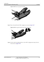
Page 121: ...clockwise as shown in Figure 5 145 Figure 5 145 Loosening two fastening screws Step 2 Hold the handles of the COAX crimping tools to open the self locking mechanism The jaw of the COAX crimping tools opens automatically as shown in Figure 5 146 AP4050DN E Hardware Installation and Maintenance Guide 5 Appendix Issue 05 2018 02 02 Huawei Proprietary and Confidential Copyright Huawei Technologies Co ...

Page 122: ...Removing the mold from the COAX crimping tools Step 4 Place the mold to be installed into the jaw of the COAX crimping tools and align the screw holes as shown in Figure 5 148 AP4050DN E Hardware Installation and Maintenance Guide 5 Appendix Issue 05 2018 02 02 Huawei Proprietary and Confidential Copyright Huawei Technologies Co Ltd 114 ...

Page 123: ... match the mold and the jaw completely Align the screw holes as shown in Figure 5 149 Figure 5 149 Aligning the screw holes Step 6 Hold the handles of the COAX crimping tools with one hand Tighten the two fastening screws clockwise Figure 5 150 and Figure 5 151shows the mold installed in the COAX crimping tool AP4050DN E Hardware Installation and Maintenance Guide 5 Appendix Issue 05 2018 02 02 Hu...

Page 124: ...ortation factors Construction structure heating and ventilation power supply lighting and fire proof construction of the equipment room should be designed by specialized construction designers to suit the environmental requirements of devices The equipment room should also follow local regulations concerning the industrial construction environmental protection fire safety and civil air defense Con...

Page 125: ...oors and windows of the equipment room must be kept closed to maintain an airtight room l Using steel doors to ensure sound insulation is recommended l No cracks or openings are allowed on the walls or floors The outlet holes on the walls or windows must be sealed Walls must be constructed such that they are smooth wear resistant dustproof flame retardant sound insulated heat absorptive and have e...

Page 126: ...quipment with the largest capacity Net height The minimum height of the equipment room should not be less than 3 m 9 84 ft The minimum height of the equipment room is the net height below overhead beams or ventilation pipes Floor The floor in the equipment room should be semi conductive and dustproof A raised floor with an ESD covering is recommended Cover the raised floor tightly and solidly The ...

Page 127: ...lace a fire hydrant in the equipment room but place it in the corridor or near the staircase Internal partition wall Separate the area where the equipment is installed from the equipment room door The partition wall can block some outside dust Installation position of the air conditioner Install air conditioner vents so that the air does not blow directly on equipment Other requirements Avoid the ...

Page 128: ...terials for ground wall and ceiling construction l Use screens on the door and windows facing outside The outer windows should be dust proof l Clean the equipment room regularly and clean the air filter monthly l Wear shoe covers and ESD clothing before entering the equipment room 5 2 1 5 Requirements for Corrosive Gases The room should be free from dusts and corrosive gases such as SO2 H2S and NH...

Page 129: ...m including computer terminals Use ESD worktables l Keep non ESD materials such as common bags foam and rubber at least 30 cm 11 81 in away from boards and ESD sensitive components 5 2 1 7 Electromagnetism Requirements for the Equipment Room All interference sources inside or outside the equipment room can cause equipment problems with capacitive coupling inductive coupling electromagnetic wave ra...

Page 130: ...ct the DC working ground positive pole of the 48 V DC power supply or the negative pole of the 24 V DC power supply with the indoor collective ground cable nearby The total ground cable should meet the maximum load of the equipment l The power equipment must have a DC working ground cable which can connect the power equipment to the collective ground cable of the telecommunication site or the prot...

Page 131: ...the same resistance Insulate the collective ground cable from the reinforcing steel bars of the building Grounding lead in The grounding lead in should be a maximum of 30 m 98 42 ft long Use the galvanized flat steel with cross sectional area of 40 mm x 4 mm 1 58 in x 0 158 in or 50 mm x 5 mm 1 97 in x 0 197 in 5 2 2 Requirements for Power Supply 5 2 2 1 Requirements for AC Power Supply An AC powe...

Page 132: ...he voltage of the power mains that supply power directly to devices exceeds the rated voltage by 10 to 5 or exceeds the voltage range that devices can support a voltage regulating device or voltage stabilizing device is required l If the mains do not supply power for the device directly or if the mains voltage exceeds the rated voltage by 15 to 10 or exceeds the input voltage range of the DC power...

Page 133: ...ed current Regulated voltage precision If the AC input voltage is in the range of 85 to 110 of the rated value and the load current is in the range of 5 to 100 of the rated value the output voltage of the rectifier ranges from 46 0 V to 56 4 V with the regulated voltage precision less than or equal to 1 Overshoot amplitude of switch on off Integral value of the DC output voltage 5 Peak noise volta...

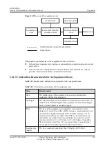
Page 134: ...e the same grounding conductor 2 The cable trays shells metal ventilation pipes metal doors and windows in the equipment room should be grounded for protection 3 The metal parts of the equipment which are electrically floating in normal conditions should be grounded for protection 4 The ground cable must be connected securely to the protective ground bar of the equipment room 5 Do not use other eq...

Page 135: ...ea measuring 30 mm x 50 mm 1 18 in x 1 97 in around the connection hole for a captive bolt Measures to prevent rust and corrosion must be taken for this area Zinc electroplating with iridescent yellow chromate conversion coating should be applied to the gasket and nut to ensure good electrical contact 6 When combining cabinets of the same type short circuiting cables are required to connect the gr...

Page 136: ... the equipment room For cables inside the equipment room install surge protection devices at the interface to the equipment The PGND cable for the surge protection devices should be as short as possible 2 The incoming and outgoing signal cables to and from the office and unused wires inside the cable should be grounded for protection 3 The Tone Data Access TDA cable must pass through the Main Dist...

Page 137: ...bles facilitate correct and orderly connection of cables and easy maintenance after installation Engineering labels are specialized for power cables and signal cables l Signal cables include network cables optical fibers and user cables l Power cables include the AC power cables and DC power cables NOTE Fill in labels according to specified requirements to keep consistency of labels in the equipme...

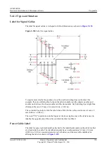
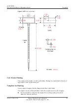
Page 138: ...e label when affixed to the cable and its size is 1 mm x 2 mm 0 04 in x 0 08 in The word TO upside down in the figure at the lower right corner of the label is used to identify the opposite end of the cable on which the label is affixed Power Cable Label The label for power cables should be attached to the identification plate on the cable ties that are attached to the cable The identification pla...

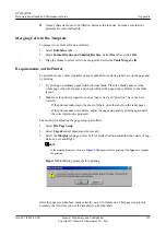
Page 139: ...tain a template from the Huawei local office to print labels The template is made in Microsoft Word Follow these instructions to use the template l You can modify the contents of the template Do not change settings of centered characters direction and fonts AP4050DN E Hardware Installation and Maintenance Guide 5 Appendix Issue 05 2018 02 02 Huawei Proprietary and Confidential Copyright Huawei Tec...

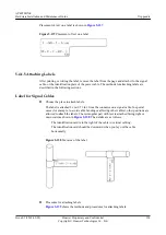
Page 140: ...tion have been set correctly If the printout conforms to the sheet of labels print the labels on the label paper If the printout does not conform adjust the page setup and try printing again until the correct printout is produced The method for adjusting the page setup is as follows 1 Select File Page Setup 2 Select Layout and set Header and Footer as 0 3 Select the Margins tab page Select Left fo...

Page 141: ...inting the text Use the space bar to move the text to the next line 5 4 1 4 Writing Labels Writing Tools To make sure the printouts are clear and legible use black markers instead of ball point pens to write the labels If no marker is available black ball point pens are allowed although not recommended Compared with ball point pens waterproof markers are better When writing with a ball point pen d...

Page 142: ...ses for example to avoid cable bending or affecting other cables other positions are allowed to attach the labels The rectangular part with text is attached facing right or downward as shown in Figure 5 158 The details are as follows The identification card is to the right of the cable in vertical cabling The identification card should be downward when you lay out the cable horizontally Figure 5 1...

Page 143: ... top of the cable in horizontal cabling or on the right side of the cable in vertical cabling as shown in Figure 5 160 The details are as follows l The identification card is to the right of the cable in vertical cabling l The identification card is on the top of the cable in horizontal cabling Make sure that the label is facing out Figure 5 160 Binding the label for the power cable The identifica...

Page 144: ...of the cable The side with TO that is facing outside carries the location information of the opposite end and the other side carries the location information of the local end In other words the information in Area 1 at one end is the same as the information in Area 2 at the other end of the cable 5 4 1 7 Precautions for Using Engineering Labels When using labels pay attention to the following poin...

Page 145: ...s from front to back are numbered from A to Z N The cabinet columns from left to right are numbered from 01 to 99 For example A01 is the cabinet in row A and column 01 B chassis number Numbered in bottom up order with two digits for example 01 C physical slot number Numbered in top down and left right order starting from 01 For example 01 is the first slot at the top left of the chassis D optical ...

Page 146: ...Content Meaning Example MN B C D R T MN cabinet number For example A01 B chassis number Numbered in bottom up order with two digits for example 01 C physical slot number Numbered in top down and left right order starting from 01 For example 01 is the first slot at the top left of the chassis D optical interface number Numbered in top down and left right order consistent with the port sequence numb...

Page 147: ...room l A01 01 05 01 R indicates that the opposite end of the optical fiber is connected to optical receiving interface 1 in slot 05 chassis 01 in the cabinet in row A column 01 in the machine room 5 4 3 Engineering Labels for Network Cables Applicable Ranges The labels can be applied to Ethernet cables Label Content Table 5 29 shows the information on both sides of the labels affixed to Ethernet c...

Page 148: ...connecting a hub and device the label on the hub end should indicate the numbers of the chassis and cabinet where the hub resides and the serial number on the hub The label on the device end should indicate the number of the chassis and cabinet where the device is located If the device is a standalone device provide the specific position of the device l For a network cable connecting a hub and an ...

Page 149: ...aning Example MN B C D MN cabinet number For example A01 is the first cabinet in row A B frame number Numbered in the bottom up order with two digits for example 03 C physical slot number Numbered with two digits in top down and left right order For example 01 D cable number Numbered with two digits in top down and left right order For example 01 MDF MN B C MN row number and column number of the M...

Page 150: ... B 48Vn MN BC BC is written right under MN B chassis number numbered in bottom up order with two digits for example 01 N power socket number numbered as 1 to 3 in the bottom up and left to right orders On the loaded cabinet side only MN is used to identify the cabinet On the power cabinet side MN identifies the row and column number of the power distribution equipment like a control cabinet and di...

Page 151: ... the above label of A01 B08 48V2 08 or sometimes 8 is the numeric identification of the terminal block PGND and BGND are two copper bars on which the terminal blocks are short circuited Therefore it makes no difference which terminal is connected to them It is only necessary to give the row and column of the power distribution box instead of giving the specific serial number of the terminal block ...

Page 152: ...n That is after the cable ties are bundled onto the cable the identification plates with the labels should face up and the text on the labels in the same cabinet should be in the same direction as shown in Figure 5 167 Figure 5 167 Labels for AC power cables Label on the loaded cabinet side indicating the position of the cable on the power distribution box Label on the distribution box side indica...

Page 153: ...ptical attenuator is used the optical power will exceed the overload power of the avalanche photodiode APD Then the optical module is burnt The preceding faults lead to temporary or long term cut off of optical signals or even cause permanent damages to the optical module affecting communication services Measures to Prevent a Loosened Optical Module 1 When installing an optical module insert it in...

Page 154: ...the connector end to the unused part of the cleaning tissue to continue 2 Cover an unused optical module with a protective cap to prevent dust as shown in Figure 5 170 Figure 5 170 Installing a protective cap If no protective cap is available use fibers to protect the optical module as shown in Figure 5 171 Figure 5 171 Using fibers to protect an optical module 3 Cover unused optical connectors wi...

Page 155: ...eding method to clean the receptacle or the optical connector In this manner the possibility of contamination can be excluded Measures to Prevent an Optical Module from Being Burnt 1 Before using an optical time domain reflectometer OTDR to test the connectivity or the attenuation of optical signals disconnect the optical fibers from the optical module Otherwise the optical module will be burnt 2 ...

Page 156: ... Return Analysis BOM Code Product Description Bar Code Fault Occurring Date Description of the Fault Phenomena Category No Software Version Reasons for Repairing Category No Category No includes the following eight types F001 Wear out damaged In warranty Period Out of warranty period F002 Deployment damaged F003 Intransit damaged F004 Version upgrade F005 Batch replace F007 Overdue spare parts ins...

Page 157: ... trays and floating nuts are correctly secured 5 AC card The AC card is secured in the cabinet or rack by guide rails or trays and the guide rails or trays and floating nuts are correctly secured 6 AC card The AC card is correctly inserted into the device slot and secured using the ejector lever 7 AC card No pins on the backplane are bent when the AC card is installed 8 Indepen dent AC The AC is g...

Page 158: ...ioning maintenance and heat dissipation APs that dissipate heat from the rear must be fixed using mounting brackets in wall mounting scenarios Ensure that there is a certain space between the APs and wall to facilitate heat dissipation 4 General APs with built in antennas should be installed in open areas and there should be no obvious obstruction in the coverage direction of the main lobe The mai...

Page 159: ...ration names of APs on the AC as well as their channels and IP addresses The lables should be attached to the front of the APs for easy observation 13 General Record AP installation positions MAC addresses interfaces of uplink PoE switches and IP addresses APs use fixed IP addresses into a table 14 Indoor AP The devices required during indoor AP installation such as the splitter coupler and antenn...

Page 160: ...le length is reserved The reserved cables are twined and placed properly to facilitate subsequent maintenance 6 Indoor AP The optical power network and feeder cables are bundled using straps one strap every 0 5 m and securely fastened 7 Outdoor AP The signal cables shall be bundled at even intervals about 1000 mm not too tight or too loose The cables shall be bundled properly with cable ties place...

Page 161: ...osed 11 General The feeder cable connectors comply with corresponding standards and are correctly connected without looseness 12 General The feeder cables power splitter coupler and surge protective devices are connected correctly and reliably in accordance with specifications 13 General Strong current and weak current cables are routed separately The power cables ground cables and signal cables a...

Page 162: ... inlet are sealed to prevent dusts Anten na 1 General The installation positions of antennas should comply with the engineering design and antennas should be securely and reliably installed 2 General There should be no obstacles in the major coverage direction of antennas The direction and downlink tilt of antennas should be adjusted based on the coverage targets 3 General There should not be meta...

Page 163: ...that between 5G antennas should be at least 0 5 m 10 Outdoor antenna If multiple APs are mounted to different poles the APs should provide signal coverage in the same direction or in back to back mode to ensure that main lobe of antennas on different APs do not face each other Recommended AP distance 44 m APs provide signal coverage in the same direction 6 m APs provide distance in back to back mo...

Page 164: ...fibers of different types cannot be used together 2 General The labels of pluggable optical modules are smoothly attached and intact and cannot be covered by the optical modules 3 General If a short distance optical fiber is used for a long distance optical module especially in loopback scenarios use an optical attenuator to prevent the optical module from being burnt 5 8 Guide to Making Drip Loop...

Page 165: ...mm 100mm ǹ Ķ Bending Radius Requirements l The bending radius of a 7 8 feeder must be more than 250 mm and that of a 5 4 feeder must be more than 380 mm AP4050DN E Hardware Installation and Maintenance Guide 5 Appendix Issue 05 2018 02 02 Huawei Proprietary and Confidential Copyright Huawei Technologies Co Ltd 157 ...

Page 166: ...ters Pa rt Nu m be r Name Vendor Applicable Device 02 31 0JF D S5700 Series ES0W2PSD0150 150W DC Power Module HUAWEI AC6605 02 22 011 9 Adapter 0degC 40degC 90V 264V 48V 2 08A FSP AD9430DN 12 AP2050DN AP2050DN E and AP2050DN S AP7050DN E R250D E 02 22 09 35 Adapter 25degC 50degC 90V 290V 56V1 07A C8 Ktec HONOR AP2050DN AP2050DN E and AP2050DN S AP4051TN AP6052DN AP7052DN AP7152DN AP7052DE R250D E ...

Page 167: ...apter 5degC 45degC 90V 270V 12V 2A China Standard DC inlet HuntKey SHILONG FUHUA 02 22 08 69 AC DC Adapter 5degC 45degC 90V 270V 12V 2A Brazil Standard DC inlet HuntKey 02 22 08 70 Adapter 5degC 45degC 90V 270V 12V 2A India Plug DC Plug HuntKey SHILONG FUHUA AC Power Supply Table 5 34 Mapping between device models and AC power adapters Par t Nu mb er Name Vendor Applicable Device 023 10J FA S5700 ...

Page 168: ...1 309 83 AC DC power module 25degC 55degC 90V 264V 12V 10A 53 5V 7 1A FSP VAPEL AC6605 AP4050DN E Hardware Installation and Maintenance Guide 5 Appendix Issue 05 2018 02 02 Huawei Proprietary and Confidential Copyright Huawei Technologies Co Ltd 160 ...

Page 169: ...P4030TN AP4050DN AP4050DN E AP4050DN S AP4051DN AP4051TN AP4130DN AP4151DN AP5010DN AP5010SN AP5030DN AP5030DN C AP5130DN AP6010SN AP6010DN AP6050DN AP6052DN AP6150DN AP6510DN AP6310SN AP7030DE AP7050DE AP7052DE AP7052DN AP7110DN AP7110SN AP7152DN AP8030DN AP8050DN AP8050DN S AP8050TN HD AP8130DN AP8130DN W AP8150DN AP4050DN E Hardware Installation and Maintenance Guide 5 Appendix Issue 05 2018 02...

Page 170: ... AP8030DN AP8130DN AP8130DN W AP8050DN AP8150DN AP8050DN S AP8082DN AP8182DN 021 311 68 AC DC Power 5degC 45degC 90V 264V 48V 0 42A SHILONG FUHUA AT815SN PSE Power Supply l Switches ACs and APs supporting the PoE out function can be used as power sourcing equipment PSE to supply power to connected powered devices PDs Ensure that the PoE out power of a PSE meet requirements of PDs AP4050DN E Hardwa...

Page 171: ...AC part number 02350MTV can supply UPoE power to AP7050DN Es AP4050DN E Hardware Installation and Maintenance Guide 5 Appendix Issue 05 2018 02 02 Huawei Proprietary and Confidential Copyright Huawei Technologies Co Ltd 163 ...

Page 172: ...adio frequency energy and if not installed and used in accordance with the instructions may cause harmful interference to radio communications However there is no guarantee that interference will not occur in a particular installation If this equipment does cause harmful interference to radio or television reception which can be determined by turning the equipment off and on the user is encouraged...

Reviews: