lp-666 Rev. 003 Rel. 001 Date 2.25.20
39
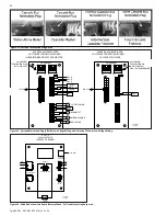
L. Cascade Follower Pump and Sensor Wiring
1. If it is desired to have the boiler control the boiler pump, connect
the Line of an externally provided 120VAC service to the TOP terminal
of the three terminal barrier strip labelled P2 NO (Normally Open).
2. Connect the boiler pump relay COIL Line input to the CENTER
terminal of P2 NO (Normally Open).
3. Connect the Neutral of an externally provided 120VAC service to
the Neutral COIL terminal of the pump relay.
4. Connect the Line of an externally provided 120VAC service to the
NO CONTACT of the pump relay.
5. Connect the NO relay CONTACT to the LINE input of the boiler
pump.
6. Connect the Neutral of an externally provided 120VAC service to
the Neutral input of the pump.
7. Connect the Earth Ground of the externally provided 120VAC to
the Earth Ground input of the pump.
8. If you are using an indirect fired water heater connected directly
to the follower boiler. Connect the Line of an externally provided
120VAC service to the TOP terminal of the three terminal barrier strip
labelled P4 NO (Normally Open).
9. Connect the DHW pump relay COIL Line input to the CENTER
terminal of P4 NO (Normally Open).
10. Connect the Neutral of an externally provided 120VAC service to
the Neutral COIL terminal of the pump relay.
11. Connect the Line of an externally provided 120VAC service to the
Neutral COIL terminal of the pump relay.
12. Connect the other NO relay CONTACT to the LINE input of the
DHW pump.
13. Connect the Neutral of an externally provided 120VAC service to
the Neutral input of the pump.
14. Connect the Earth Ground of the externally provided 120VAC to
the Earth Ground input of the pump.
If desired, an alarm bell or light can be connected to the alarm
contacts of the boiler. The normally closed alarm contact may be
used to turn a device off if the boiler goes into lockout mode. The
alarm contacts are rated 5 amps at 120 VAC.
To connect an alarm device, connect the power for the device to the
center terminal of the three terminal barrier strip labelled ALARM
(P8). Connect the alarm device hot wire to the top terminal of the
three terminal barrier strip labelled ALARM (P8). Connect the neutral
or return of the alarm device to the neutral or return of the power
for the alarm device.
To connect a device that should be powered off during a boiler
lockout condition, follow the same instructions as above and use
the bottom terminal of ALARM NC rather than the top ALARM NO
terminal.
NOTE:
In a cascade system, the alarm output of the boiler addressed
as #1 will activate if any boiler has a lockout condition. The alarm
of boilers addressed #2-15 will only activate if a lockout condition
occurs on that specific boiler.
M. Variable Speed Pumping
Variable speed pump support is available on the primary loop of all
models. This feature controls pump speed via an analog 0-10VDC signal
supplied via the 0-10VA connection on the Customer Connection
Board.
When this feature is in use, an installer selected Delta T is maintained
with the Supply and Return sensors, increasing efficiency and providing
better system temperature control. When the difference between the
Supply and Return temperatures is greater than the desired setting,
the pump will increase speed and flow to compensate. Conversely,
if the Delta T is less than the desired setting, the pump will decrease
speed and flow to compensate.
NOTE:
This feature may be used in Primary / Secondary piping
arrangements ONLY!
Variable Speed Pumping Wiring:
1. On the High Voltage Field Connection Board, connect the Line of an
externally provided 120VAC service to the TOP terminal of the three
terminal barrier strip labelled P2 NO (Normally Open).
2. Connect the boiler pump relay COIL Line input to the CENTER
terminal of P2 NO (Normally Open).
3. Connect the Neutral of an externally provided 120VAC service to the
Neutral COIL terminal of the pump relay.
4. Connect the Line of an externally provided 120VAC service to the NO
CONTACT of the pump relay.
5. Connect the other NO relay CONTACT to the LINE input of the boiler
pump.
6. Connect the Neutral of an externally provided 120VAC service to the
Neutral input of the pump.
7. Connect the Earth Ground of the externally provided 120VAC to the
Earth Ground input of the pump.
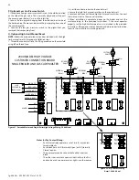
8. On the Low Voltage Field Connection Board, connect the 0-10v input
wires on the variable speed pump to the terminals marked 0-10VA+
(Positive) and 0-10VA- (Negative).
NOTE:
When making wiring connections, ensure proper polarity or the
system will not operate properly.
5. Connect the other NO relay CONTACT to the LINE input of the
boiler pump.
6. Connect the Neutral of an externally provided 120VAC service to
the Neutral input of the pump.
7. Connect the Earth Ground of the externally provided 120VAC to
the Earth Ground input of the pump.
8. On the Low Voltage Field Connection Board in the front of the
boiler, connect the system pipe sensor to the terminals marked
SYS+ and SYS-.
9. Connect the outdoor sensor (if used) to the terminals marked
OUT+ and OUT-.
6. Connect the signal to start the system to the terminals marked
TT+ and TT-.
NOTE:
This signal can come from a room thermostat or a dry contact
closure. No power of any voltage should be fed into either of these
terminals.
N. Optional 0-10 Volt Building Control Signal
1. A signal from a building management system may be connected to
the boiler to enable remote control. This signal should be a 0-10 volt
positive-going DC signal. When this input is enabled using the installer
menu, a building control system can be used to control the set point
temperature or firing rate of the boiler. The control interprets the 0-10
volt signal as follows; when the signal is between 0 and 1 volts, the
boiler will ignite. As the signal continues to rise towards its maximum
of 10 volts, the boiler will increase in either set point temperature or
firing rate depending on the setting of Function 17 in the Installer
Menu. See this manual for details on the setting of Functions 16 and
17 for this option.
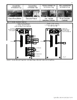
2. Connect a building management system or other auxiliary control
signal to the terminals marked 0-10V+ and 0-10V– on the Field
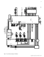
Connection Board (shown in Figure 35). Caution should be used to
ensure that the 0-10V+ connection does not become connected to
ground.
O. Optional High Gas Pressure Switch
1. If an optional high gas pressure switch is used, it should be installed
on the side of the gas valve. This is normally closed and will open if the
pressure goes above 15.5” w.c. on the outlet side.
2. Locate the two pigtails hanging from the electrical box inside of the
boiler cabinet. Remove and discard the jumper plug from one of the
unused pigtails.
3. Connect the high gas pressure switch to the pigtail that you removed
the jumper plug from.

