


lp-666 Rev. 003 Rel. 001 Date 2.25.20
38
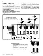
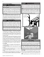
E. Low Voltage Connections for Standard Boiler
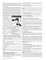
1. All low voltage cables should enter the electrical junction box
through the provided knock out holes as shown in Figure 30.
2. Connect all low voltage field devices to the low voltage terminal
strip located in the electrical junction box.
F. Thermostat
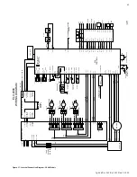
1. Connect the room thermostat to the terminals marked TT- and TT+
of the Field Connection Board (shown in Figure 35). Alternately, any
dry contact closure across these terminals will cause the boiler to run.
Caution should be taken to ensure neither of the terminals becomes
connected to ground.
2. Mount the thermostat on an inside wall as centrally as possible to
the area being heated, but away from drafts or heat producing devices
such as television sets that could influence the ability of the thermostat
to measure room temperature.
3. If the thermostat is equipped with an anticipator and it is connected
directly to the boiler, the anticipator should be set at .1 amps. If the
thermostat is connected to other devices, the anticipator should be
set to match the power requirements of the device it is connected
to. See the instruction manual of the connected devices for further
information.
circuit between the common and ALARM NO is open during normal
operation. HTP offers an Alarm System Kit (part # 7350P-602).
G. Outdoor Sensor
NOTE:
There is no connection required if an outdoor sensor is not used
in this installation.
1. If using an outdoor sensor, connect wires for sensor to the terminals
marked OUT+ and OUT- on the Low Voltage Field Connection Board.
Caution should be used to ensure neither of these terminals becomes
connected to ground.
2. Use a minimum 22 AWG wire for runs of 100 feet or less and minimum
18 AWG wire for runs of up to 150 feet.
3. Mount the outdoor sensor on an exterior surface of the building,
preferably on the north side in an area that will not be affected by
direct sunlight and will be exposed to varying weather conditions.
H. Indirect Sensor
NOTE:
There is no connection required if an indirect water heater is
not used in this installation.
1. The boiler will operate an indirect fired water heater with either a
thermostat type aquastat installed in the indirect tank, or an HTP
7250P-325 tank sensor. When a tank sensor is used, the control will
automatically detect its presence and a demand for heat from the
indirect water heater will be generated when the tank temperature
falls below the user selected set point by more than the user selected
offset. The demand will continue until the sensor measures that the
indirect water heater temperature is above the set point.
2. Connect the indirect tank sensor (7250P-325) to the terminals
marked DHW+ and DHW- on the Low Voltage Field Connection Board.
Failure to use the correct sensor may result in tank temperature
being either above or below set point, and could result in decreased
performance, substantial property damage, or heightened risk of
injury or death due to scalds.
WARNING
!
Caution should be used to ensure neither of these terminals becomes
connected to ground.
NOTE:
If sensor wires are located in an area with sources of potential
electromagnetic interference (EMI), the sensor wires should be
shielded, or the wires routed in a grounded metal conduit. If using
shielded cable, the shielding should be connected to the common
ground of the boiler.
I. UL 353 Internal Low
Water Cut-Off (Factory
Installed)
The supplied internal Low
Water Cutoff (LWCO) meets
UL 353 requirements to
function as a safety, locking
out the boiler when water
level is inadequate for safe
operation. See Service Mode,
this manual, for instructions
on how to test and reset the
Internal LWCO.
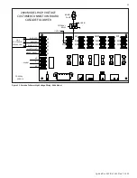
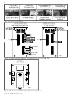
J. Wiring of Cascade
System Communication
Bus
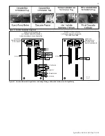
1. A Cascade Bus Termination
Plug has been installed on
the customer connection
board of this boiler. The
purpose of this plug is to
stabilize communication
between multiple boilers
and reduce electrical “noise”.
See Figure 34 for Cascade Bus Termination Plug installation detail.
NOTE:
It is important that the termination plug in multiple boilers
(cascaded units) be installed as depicted in Figure 34. Leave the plug
installed in the J6 port on the Master boiler. Remove the plug on
intermediate Follower boilers. Move the plug to the J7 port on the
final Follower boiler.
2. Use standard CAT3 or CAT5 computer network patch cables to
connect the communication bus between each of the boilers. These
cables are readily available at any office supply, computer, electronic,
department or discount home supply store in varying lengths. If you
possess the skills you can also construct custom length cables.
3. It is recommended to use the shortest length cable that will
reach between the boilers and create a neat installation. Do not run
unprotected cables across the floor where they may become wet
or damaged. Avoid running communication cables parallel and
close to or against high voltage (120 volt or greater) wiring. HTP
recommends that the maximum length of communication bus
cables not exceed 200 feet.
4. Route the communication cables through one of the knockouts
in the cabinet.
5. Connect the boilers in a daisy chain configuration. It is best to wire
the boilers using the shortest wire runs rather than trying to wire
them in the order that they are addressed. The communication bus
jacks on the customer connection panel are interchangeable so you
can use either one or both in any order to connect the cable.
If you have connected the boilers to each other properly, there will
be no open communication connection ports.
K. Cascade Master Pump and Sensor Wiring
SYS Pump Wiring
1. On the High Voltage Field Connection Board in the rear of the
boiler, connect the Line of an externally provided 120VAC service to
the TOP terminal of the three terminal barrier strip labelled P6 NO
(Normally Open).
2. Connect the boiler pump relay COIL Line input to the CENTER
terminal of P6 NO (Normally Open).
3. Connect the Neutral of an externally provided 120VAC service to
the Neutral COIL terminal of the pump relay.
4. Connect the Line of an externally provided 120VAC service to the
NO CONTACT of the pump relay.