


NOTICE:
This drawing is the property of Hi Performance Electric Vehicle Systems Inc., and/or its subsidiaries and affiliates (individually
and collectively “HPEVS”), and contains highly proprietary, confidential, and trade secret information of HPEVS. The recipient of this
drawing agrees (a) to use the information contained herein for the purpose for which it was furnished by HPEVS (b) to return this drawing
upon HPEVS request. This notice shall appear on any complete or partial reproduction of this drawing.
ORANGE/ WHITE 20 AWG
I/O GROUND
PEDAL INTERLOCK
12V POWER CNTRL
5V POWER CNTRL
TX SERIAL
RX SERIAL
ENCODER PHASE A
ENCODER PHASE B
REVERSE
KSI
MAIN CONTACTOR
COIL RETURN
BLUE 20 AWG
BLACK/ BLUE 20 AWG
GREEN 20 AWG
BLUE/ WHITE 20 AWG
YELLOW 20 AWG
RED/ BLUE 20 AWG
RED / WHITE 20 AWG
WHITE 22 AWG
GREEN 22 AWG
TAN 20 AWG
TAN/ BLACK 20 AWG
MOTOR TEMP
OPTIONAL ECONOMY SWITCH (NOTE*7)
YELLOW/ BLACK 20 AWG
FWD/ REV SWITCH (NOTE*8)
R3
MOLEX MINI FIT JR
39-01-2080
BLACK 22 AWG
RED 22 AWG
WHITE 22 AWG
CAN TERMINATION
S3
GREEN 22 AWG
TACHOMETER DRIVER
START BUTTON INPUT
BLACK 20 AWG
BROWN 20 AWG
CLUTCH/ SHIFT SWITCH
N.C. PEDAL INTERLOCK (SEE THROTTLE SCHEMATICS)
ECONOMY MODE
CAN HIGH
WHITE/ BLUE 20 AWG
MULTIPLE
CONDUCTOR
CABLE
OPTIONAL CLUTCH / SWITCH (NOTE *6)
R1
AMP
#776164-1
1
2
3
5
6
7
8
9
11
12
13
14
21
23
25
26
35
28
29
31
32
33
34
1
6
5
8
PRECHARGE
GREY 20AWG
PURPLE 20 AWG
ORANGE / BLACK 20 AWG
R5
DEUTSCH
DTM-06-2S
ORANGE 20 AWG
CAN LOW
GREY 20 AWG
OPTIONAL
CAN BUS
SEE BRAKE
SCHEMATICS
BRAKE SWITCH INPUT
LABEL
“# 14”
WHITE/ BLACK 20 AWG
MALE 3/16” QD
OPTIONAL BRAKE SWITCH INPUT (NOTE *9)
S1
FEMALE
3/16” QD
LABEL
“# 7”
IGNITION KEY
SWITCH
OEM WIRING
LOCK
ACC
ON
START
OEM WIRING
0
12
TACHOMETER
6
Pull up Resistor
(Note *3)
OEM WIRING
12V
Optional Start
Switch (Note*5)
BRAKE LIGHT RELAY
ORANGE 20AWG
SEE BRAKE
SCHEMATICS
1
2
S2
LABEL
“# 26”
FEMALE
1/4” QD
BRAKE POT WIPER
MALE 3/16” QD
LABEL
“# 17”
YELLOW/ RED 20 AWG
FEMALE 3/16” QD
SEE BRAKE
SCHEMATICS
17
POT WIPER
YELLOW/ WHITE 20 AWG
POT HIGH
BLACK/ WHITE 20 AWG
POT LOW
PURPLE/ WHITE 20 AWG
FEMALE 3/16” QD
MALE 3/16” QD
FEMALE 1/4” QD
MALE 1/4” QD
LABEL
“# 15”
LABEL
“# 18”
SEE THROTTLE
SCHEMATICS
15
16
18
A
B
+A1
A2-
COM
NO
4
U
V
W
B +
B -
35
PI
N
CO
NN
EC
TO
R
(SE
E R
1)
A
B
+
-
VISIO
1
1
B
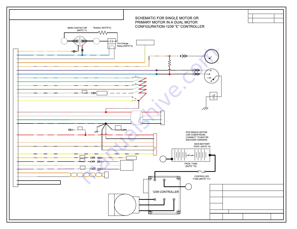
1239 “E” CONTROLLER
ON-ROAD VEHICLE CONVERSION /
PRIMARY DUAL MOTOR SCHEMATICS
NONE
none
4/11/16
A
DRW SIZE
APPLICABLE
SOFTWARE
CAD TYPE
UNIT
DRAWING
TITLE
SCALE
DATE
REVISION
SHEET
HPEVS
OF
SUPPLIER PART
1010‐AUTO1239‐PRI‐VER365.000
HW-1010AUTO1239-HPG
Version 365.000 & Up
NOTES:
(*1)
Use supplied Contactor (GIGAVAC Part # GV200PA-1).
Use only a contactor WITHOUT A PWM AND COIL
SUPPRESSOIN. FAILURE TO DO SO CAN CAUSE
CONTROLLER FAILURE AND WILL VOID THE
WARRANTY.
(*2) Use supplied Pre-Charge Resistor and Relay (Tyco
Electronics Part # T9AP1D52-12).
For Coil connection, connect to small terminals.
(*3) Tachometers that are designed to work off of an ignition
coil may not function in this application. Some Tachometers
may need a pull up resistor of 4.7K Ω to function
(*4) A Battery Management System (BMS) is strongly
recommended if Lithium Ion batteries are used. Possible
source of BMS is Ewert Energy System’s ORION BMS
(www.orionbms.com)
(*5) Start switch is required if
Idle or Creep Torque
parameters are ENABLED
. See Programming Instructions.
A start switch CAN be used without IDLE.
See programming instructions for information
(*6) Install the Optional Clutch/Shift Switch so that is ON
when the clutch pedals is pressed. When clutch pedal is
pressed the regen setting is changed to Shift Neutral
Braking Parameter to prevent the motor from stalling during
gear shifting. In a clutch less system, this allows you to set
the coast down rate of the motor so that the gears align
properly.
See Instructions on SHIFT-NEUTRAL BRAKING
PARAMETERS.
(*7) Allows the use of ECONO Mode Parameters.
See Programming Instructions.
(*8) Forward is CLOCKWISE motor rotation from Encoder
end view. Depending on Transmission configuration, use
either wire to obtain desired rotation. Use FWD & REV
Switch in direct drive applications.
(*9) See Brake Schematics
(*10) Use Pack Fuse rated at 400A for Single controller
applications. For Dual controller use 800A Pack Fuse.
(*11) Only for Dual motor application. Use Controller Fuse
rated at 400A for each controller.
(*12) Gives access to Drive System information. Required to
access Programming and Diagnostic modes.
See Programming Instructions.
PROGRAMMING
PORT
REV
DESCRIPT ION
APPROVED
A
Ini ti al Rel ease
4/ 11/ 2016
REVISIONS
U
MOTOR
MO
TO
R
ENCO
DE
R
H
AR
N
ESS
C
O
N
N
EC
TO
R
W
V
P4
DEUTSCH
DT-04-6P
WHITE/ RED 20 AWG
MENU BUTTON
10
MENU BUTTON (NOTE *12)
FORWARD
WHITE 20 AWG
22
P4
DEUTSCH
DTM-04-4P
P4B
DEUTSCH
DTM-04-2P
1
2
3
4
1
2
Summary of Contents for Curtis 1239 E
Page 8: ...8 GENERIC FULL ELECTRICAL SCHEMATICS 1239 E CONTROLLERS ...
Page 15: ...15 ...
Page 18: ...18 ...
Page 20: ...20 ...
Page 45: ...45 ...