background image

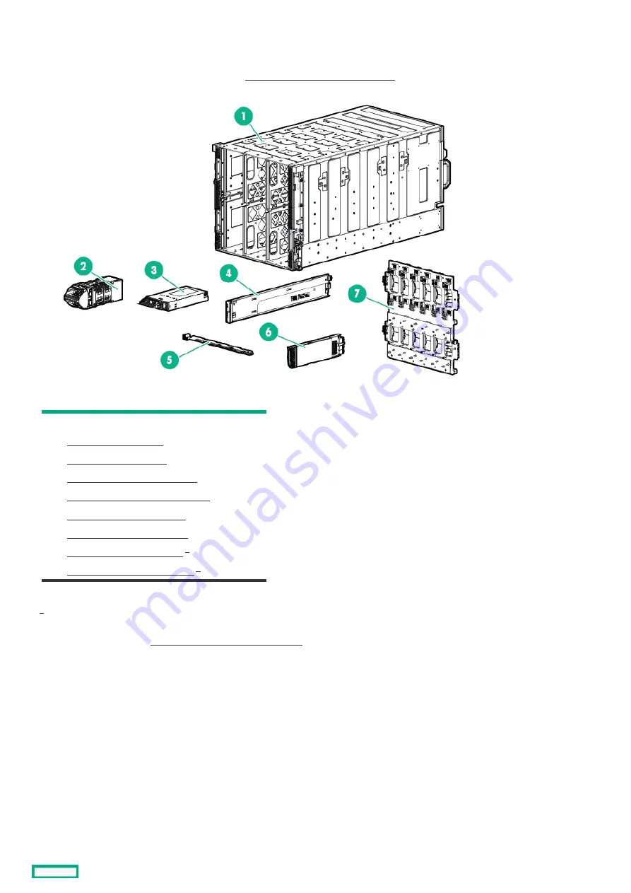
System components

System components

Hewlett Packard Enterprise continually improves and changes product parts. For complete and current supported parts information, see
the Hewlett Packard Enterprise PartSurfer website http://www.hpe.com/info/partssurfer

http://www.hpe.com/info/partssurfer.

Item

Item Description

Description

1

HPE Synergy 12000 Frame

2

Hot-plug fan spare part

3

Power supply spare part

4

Front panel assembly spare part

5

Fan interposer assembly spare part

6

Frame link module spare part

7

Midplane assembly spare part

8

Appliance module spare part

9

Interconnect module spare part

Not shown

For more information, see " Removal and replacement procedures."

1

1

1

System components

18

Summary of Contents for Synergy 12000 Frame

Page 1: ...HPE Synergy 12000 Frame Maintenance and Service Guide Part Number 806423 006a Published April 2022 Edition 6a...

Page 2: ...the express warranty statements accompanying such products and services Nothing herein should be construed as constituting an additional warranty Hewlett Packard Enterprise shall not be liable for te...

Page 3: ...nterconnect module spare part 1 3 Cables and miscellaneous components 1 3 1 Frame cabling spare part 1 3 2 Networking cable spare parts 1 3 3 Transceiver spare parts 2 Customer self repair 3 Removal a...

Page 4: ...21 Removing and replacing a rear cage 3 22 Removing and replacing the rack rails 3 22 1 Replacing the rack rails 4 Component and LED identification 4 1 Information pull tabs 4 2 Frame front components...

Page 5: ...al Connect SE 40Gb F8 Module for HPE Synergy components 4 3 16 HPE Synergy 40Gb F8 Switch Module LEDs and buttons 4 3 17 HPE Synergy 40Gb F8 Switch Module components 4 3 18 Mellanox SH2200 Switch Modu...

Page 6: ...Illustrated parts catalog This chapter lists the hardware spare parts supported by the frame Illustrated parts catalog 6...

Page 7: ...n 1 HPE Synergy 12000 Frame 2 Power supply blank spare part 3 Interconnect module blank spare part 4 Device bay blank spare part 5 Frame link module blank spare part 6 Rack rail kit spare part 7 Bezel...

Page 8: ...Power supply blank spare part Customer self repair mandatory Description Spare part number Power supply blank 813564 001 Power supply blank spare part 8...

Page 9: ...Interconnect module blank spare part Customer self repair mandatory Description Spare part number Interconnect module blank 813563 001 Interconnect module blank spare part 9...

Page 10: ...Device bay blank spare part Customer self repair mandatory Description Spare part number Device bay blank 813561 001 Device bay blank spare part 10...

Page 11: ...Frame link module blank spare part Customer self repair mandatory Description Spare part number Frame link module blank 813560 001 Frame link module blank spare part 11...

Page 12: ...Rack rail kit spare part Customer self repair mandatory Description Spare part number Rack rail kit 813568 001 Rack rail kit spare part 12...

Page 13: ...Bezel assembly spare part Customer self repair mandatory Description Spare part number Bezel assembly includes left and right 813565 001 Bezel assembly spare part 13...

Page 14: ...Frame lift handles spare part Customer self repair mandatory Description Spare part number Frame lift handle 813567 001 Frame lift handles spare part 14...

Page 15: ...Device bay shelf spare part Customer self repair mandatory Description Spare part number Device bay shelf 813569 001 Device bay shelf spare part 15...

Page 16: ...Device bay half shelf spare part Customer self repair mandatory Description Spare part number Device bay half shelf 813570 001 Device bay half shelf spare part 16...

Page 17: ...Appliance bay blank spare part Customer self repair mandatory Description Spare part number Appliance bay blank 813562 001 Appliance bay blank spare part 17...

Page 18: ...e com info partssurfer Item Description 1 HPE Synergy 12000 Frame 2 Hot plug fan spare part 3 Power supply spare part 4 Front panel assembly spare part 5 Fan interposer assembly spare part 6 Frame lin...

Page 19: ...Hot plug fan spare part Customer self repair mandatory Description Spare part number Hot plug fan 807967 001 Hot plug fan spare part 19...

Page 20: ...hot plug P28296 001 2900 3400W hot plug Platinum 882168 001 2650W performance hot plug Titanium Plus 813829 001 2650W HV DC hot plug 813833 001 2650W 277V AC hot plug 813832 001 2650W 48V DC hot plug...

Page 21: ...Front panel assembly spare part Customer self repair mandatory Description Spare part number Front panel assembly 807965 001 Front panel assembly spare part 21...

Page 22: ...Fan interposer assembly spare part Customer self repair no Description Spare part number Fan interposer assembly 807966 001 Fan interposer assembly spare part 22...

Page 23: ...k module spare part Customer self repair mandatory Description Spare part number HPE Synergy Frame Link Module 2 port 807963 001 HPE Synergy 4 Port Frame Link Module P04749 001 Frame link module spare...

Page 24: ...Midplane assembly spare part Customer self repair no Description Spare part number Midplane assembly 869597 002 Midplane assembly spare part 24...

Page 25: ...e spare part The appliance module removal and replacement procedures are available in the HPE Synergy Appliance Maintenance and Service Guide on the Hewlett Packard Enterprise website Appliance module...

Page 26: ...for HPE Synergy 881769 001 Brocade 32Gb FC Fibre Channel Switch Module 881769 001 HPE Virtual Connect SE 16Gb Fibre Channel Module for HPE Synergy 785338 001 Brocade 16Gb 12 Fibre Channel SAN Switch...

Page 27: ...parts For complete and current supported parts information see the Hewlett Packard Enterprise PartSurfer website http www hpe com info partssurfer Spare parts are also available for miscellaneous cabl...

Page 28: ...cabling spare part Customer self repair mandatory Description Spare part number HPE Synergy 4p Frame Link Module USB Adapter for HPE Synergy 4 Port Frame Link Module P06996 001 Frame cabling spare pa...

Page 29: ...AC 3 00 m 118 11 in 487969 001 X242 10G to SFP DAC 3 00 m 118 11 in J9283 61201 40G QSFP DAC 1 00 m 39 37 in 746963 001 40G QSFP DAC 3 00 m 118 11 in 746964 001 40G QSFP DAC 5 00 m 196 85 in 746965 00...

Page 30: ...4 in 656428 001 HPE Premier Flex LC LC OM4 2f cable 5 00 m 196 85 in 656429 001 HPE Premier Flex LC LC OM4 2f cable 15 00 m 590 55 in 656430 001 HPE Premier Flex LC LC OM4 2f cable 30 00 m 1 181 10 in...

Page 31: ...504441 001 8Gb SFP Short Wave B Series 670504 001 8Gb SFP B series 25km FC SFP 25 km 15 53 miles 582640 001 8Gb SFP short wave FC transceiver 468508 001 10G SFP SR transceiver 300 m 984 ft 456096 001...

Page 32: ...to replace these parts you will be charged for the travel and labor costs of this service R paration par le client CSR Les produits Hewlett Packard Enterprise comportent de nombreuses pi ces CSR Custo...

Page 33: ...io per i soli componenti Hewlett Packard Enterprise fornir gratuitamente le parti di ricambio Per il servizio di garanzia per i soli componenti obbligatoria la formula CSR che prevede la riparazione d...

Page 34: ...e por el de sustituci n En el caso de todas sustituciones que lleve a cabo el cliente Hewlett Packard Enterprise se har cargo de todos los gastos de env o y devoluci n de componentes y escoger la empr...

Page 35: ...titua pode haver ou n o a cobran a de taxa adicional dependendo do tipo de servi o de garantia destinado ao produto OBSERVA O Algumas pe as da Hewlett Packard Enterprise n o s o projetadas para o repa...

Page 36: ...Customer self repair 36...

Page 37: ...Customer self repair 37...

Page 38: ...Customer self repair 38...

Page 39: ...Customer self repair 39...

Page 40: ...Removal and replacement procedures Removal and replacement procedures 40...

Page 41: ...Required tools The following items are required for some procedures T 10 Torx screwdriver T 15 Torx screwdriver T 25 Torx screwdriver Required tools 41...

Page 42: ...ocumentation The appliance module removal and replacement procedures are available in the HPE Synergy Appliance Maintenance and Service Guide on the Hewlett Packard Enterprise website Appliance module...

Page 43: ...Safety considerations Before performing service procedures review all the safety information Safety considerations 43...

Page 44: ...sitive component or assembly Use one or more of the following methods when handling or installing electrostatic sensitive parts Use a wrist strap connected by a ground cord to a grounded workstation o...

Page 45: ...gle source of power does not necessarily remove power from any portion of the system When performing any service other than hot plug module replacement you must completely disconnect all power to that...

Page 46: ...rame The following actions might be required for some replacement procedures Power down all compute modules Power down all storage modules Power down the appliance modules Power down the frame Prepari...

Page 47: ...HPE Synergy Console 2 Sign in to HPE OneView with administrator privileges Minimum required privileges for the next step Infrastructure administrator Server administrator for enclosure server and fra...

Page 48: ...ided to the system If the UID LED is flashing blue a remote session or a firmware update is in progress To power down the compute module use one of the following methods To perform a graceful shutdown...

Page 49: ...e For more information about storage module LEDs see the HPE Synergy 12Gb SAS Storage User Guide on the Hewlett Packard Enterprise website http www hpe com info synergy docs 3 To remove all power from...

Page 50: ...ance console of the appliance module to be serviced For HPE Synergy Image Streamer from the main menu of the Image Streamer interface select Deployment Appliances Actions Shutdown This will power down...

Page 51: ...3 Verify that the compute module UID LED is not flashing blue and that the compute module is in standby mode For more information see the compute module user guide on the Hewlett Packard Enterprise w...

Page 52: ...graded but operational state for a short time no further action is required However if the frame is expected to be powered down for an extended time Hewlett Packard Enterprise recommends that the CAT6...

Page 53: ...HPE Synergy Console connections HPE Synergy Console connections 53...

Page 54: ...configure the laptop computer Ethernet port to the IP address 192 168 10 2 with the subnet mask 255 255 255 0 2 Use a CAT5 cable to connect the laptop computer Ethernet port to the laptop port on a f...

Page 55: ...ing to an HPE Synergy 4 Port Frame Link Modules requires an HPE Synergy 4 Port Frame Link Module USB Adapter Prerequisites A frame link module is installed in a frame link module bay Procedure 1 Conne...

Page 56: ...the frame with the monitor cable 3 Connect a USB keyboard and mouse to the USB ports on the monitor and connect the monitor USB to the frame with the USB cable Alternatively connect the USB keyboard...

Page 57: ...slot at the bottom of the frame bezel pull the bottom of the bezel out and then up 2 Pull the top of the bezel away from the frame and then remove the bezel from the frame To replace the component rev...

Page 58: ...al procedure If replacing a full height device bay blank ensure that the coupler is installed Procedure 1 Fit the coupler plate into the slots on top of the blank and then slide the coupler plate back...

Page 59: ...3 Install the full height blank into the device bay Removing and replacing a device bay blank 59...

Page 60: ...ciated device bays before removing and replacing the device bay shelf Procedure 1 Press and hold the release latches to release the locking mechanism 2 Slide the removable shelf out of the frame To re...

Page 61: ...pute module from the adjacent bay before removing and replacing the half shelf Procedure 1 To release the locking mechanism press and hold the shelf release latch 2 Slide the half shelf towards the fr...

Page 62: ...helf Procedure 1 Align the spools to the keyhole slots in the frame 2 Insert the spools into the keyhole slots and slide the half shelf towards the rear of the frame until it locks into place Replacin...

Page 63: ...Removing and replacing an appliance bay blank Remove the component as indicated Slide the appliance module into the bay until it clicks into place Removing and replacing an appliance bay blank 63...

Page 64: ...placing hot plug fans All 10 fans must be populated at all times Squeeze the handle and then pull the fan from the frame To replace the component reverse the removal procedure Removing and replacing h...

Page 65: ...dles remove the rear lift handles from each side of the frame Then slide the frame halfway into the rack 2 Slide the frame into the rack until the front lift handles are close to the rack Remove the f...

Page 66: ...ll a frame link module blank in any unused frame link module bay Procedure 1 Press down on the release buttons 2 Remove the frame link module blank To replace the component reverse the removal procedu...

Page 67: ...link module Procedure 1 Push the top tab in The release lever pops open 2 Open the release lever 3 Remove the frame link module To replace the component reverse the removal procedure Removing and rep...

Page 68: ...a front panel assembly Procedure 1 Remove the bezel from the right side of the frame 2 Remove the front panel assembly To replace the component reverse the removal procedure Removing and replacing a f...

Page 69: ...interconnect module blanks in any unused interconnect module bays To remove the component use the pull slots to remove the interconnect module blank To replace the component reverse the removal proce...

Page 70: ...cing an interconnect module Procedure 1 Press the tab and open the release lever 2 Remove the interconnect module To replace the component reverse the removal procedure Removing and replacing an inter...

Page 71: ...he risk of personal injury from hot surfaces allow the power supply or power supply blank to cool before touching it Procedure 1 Press the release lever 2 Squeeze the handle and pull the power supply...

Page 72: ...ent do not connect the power cord to the power supply until the power supply is installed Install power supply blanks in any unused power supply bays Procedure 1 If using zip ties unfasten the reusabl...

Page 73: ...in 10 41 mm Bolt hole size 0 20 in 5 08 mm Hole spacing 0 63 in 16 00 mm Install power supply blanks in any unused power supply bays Prerequisites Be sure the 48V DC power cables are installed For mo...

Page 74: ...at level work surface 5 Open the input connector on the power supply 6 Using a T25 Torx screwdriver disconnect and remove the power cables Retain the cables and T25 screws for to install on the replac...

Page 75: ...sert the two hole lug through the aperture labeled 48V on the power supply input connector 5 Secure the two hole lug to the 48V DC input connector terminal with two T25 screws 6 Using a torque control...

Page 76: ...r supply into the frame until it locks into place The power supply is marked with TOP to ensure proper orientation during installation 13 Connect the power cables to the 48V DC power source 14 Turn on...

Page 77: ...pliance assembly b Remove the front panel assembly c Remove any installed compute modules 5 From the front of the frame use a T 25 Torx screwdriver to unscrew the six captive screws 6 From the rear of...

Page 78: ...To replace the component reverse the removal procedure Removing and replacing a rear cage 78...

Page 79: ...ail Pull the front rail release lever to release the front rack rail tabs then shorten the rail 2 Pull the rear rail release lever to release the rear rack rail tabs 3 Remove the rack rail 4 Repeat th...

Page 80: ...2 Align the rear end of the rail with the rack rear column 3 Position the rail tabs next to the square openings in the rack rear column 4 Keeping the rail level insert the rear rail tabs into the rack...

Page 81: ...7 Insert the front rail tabs into the rack front column and then push the tabs down into place 8 Repeat the procedure for the right rack rail Replacing the rack rails 81...

Page 82: ...Component and LED identification Component and LED identification 82...

Page 83: ...top left has the frame product ID serial number and the device bay numbering for the frame front bays 2 The rear pull tab top left has the bay numbering for the frame rear bays 3 The serial label pull...

Page 84: ...Information pull tabs 84...

Page 85: ...and device bays Item Description 1 Device bays Compute modules and storage modules 2 Front panel Provides access to the HPE Synergy Console through KVM or laptop 3 Appliance bays Frame front componen...

Page 86: ...h other between sets of vertical partitions if all device bays in the frame are to be used For an odd number of single wide full height device modules an even number must be installed next to each oth...

Page 87: ...device modules can be installed in a frame Figure 3 Vertical partitions Horizontal frame partitions The horizontal frame partitions are removable shelves that divide a full height device bay into a ha...

Page 88: ...Figure 5 Optional horizontal half shelf Device bay partitions 88...

Page 89: ...neView or to the HPE Synergy Console 3 Laptop port Provides single laptop access to the frame link module using an RJ 45 Ethernet 100BASE TX connection 4 Monitor port Provides connectivity for a monit...

Page 90: ...vides health status of the appliance module If the Health LED indicates a warning or a critical error connect to the HPE Synergy Console to troubleshoot 3 Activity LED Indicates which appliance module...

Page 91: ...the appliance module Press and hold until activity LED is flashing green Initiates reimaging of the appliance module from files on the USB flash drive plugged into the appliance module 6 USB port USB...

Page 92: ...Appliance bay numbering Appliance bay numbering 92...

Page 93: ...o link or activity on any Mezzanine NIC 4 Power On Standby button and system power LED Solid green System on Flashing green 1 Hz cycle per sec Performing power on sequence Solid amber System in standb...

Page 94: ...located on the compute module Power On Standby button System power LED Definition Off No power present Solid amber System is in standby Flashing green 1 Hz cycle per sec Performing power on sequence S...

Page 95: ...NVDIMM LED identification Item LED description LED color 1 Power LED Green 2 Function LED Blue NVDIMM LED identification 95...

Page 96: ...t the NVM controller is not working or not ready On Off 1 AC power is on 12V rail and the NVM controller is ready On On 2 AC power is off or the battery is off 12V rail off Off Off 3 AC power is on 12...

Page 97: ...on is in progress Flashing 1 The restore operation is successful Solid or On 2 Erase is in progress Flashing 3 The erase operation is successful Solid or On 4 The NVDIMM N is armed and the NVDIMM N is...

Page 98: ...es are being located 3 Health status Green Normal operation Flashing amber Degraded condition Flashing red Critical condition 4 Drive status in priority order Solid amber One or more drives failed Fla...

Page 99: ...Frame rear components Item Description 1 Fans 10 2 Interconnect modules up to 6 3 Power supplies 6 4 Frame link modules 2 Frame rear components 99...

Page 100: ...2 2 and 5 Interconnect modules These interconnect modules are redundant pairs on fabric 3 3 and 6 Fans 1 through 10 Power supplies 1 through 6 NOTE The arrow direction on each of the power supply icon...

Page 101: ...duct QuickSpecs on the Hewlett Packard Enterprise website Item Description Function 1 MGMT port activity LED Reports MGMT port activity Flashing green Activity on the MGMT port Off No activity on the...

Page 102: ...erved for future use 7 Appliance port 1 Reserved for future use 8 UID button LED Toggles the UID LED on or off Solid blue Activated Off Deactivated Flashing blue Firmware upgrade is in progress on the...

Page 103: ...ultiframe configuration Provides management ring frame link topology connectivity for automatic frame discovery by HPE OneView 12 MGMT port SFP connector that provides the following functions IMPORTAN...

Page 104: ...Solid green MGMT port is connected Off MGMT port is not connected 4 Health LED Provides the health status of the frame link module Solid green Normal operation Flashing amber Warning Flashing red Cri...

Page 105: ...Provides high availability management network connectivity between LINK ports on two frame link modules in the same frame for a single frame configuration Frame link modules in different frames as par...

Page 106: ...wer to the power supply or power supply failure Connect to the HPE Synergy console and check for power supply error messages Solid green Normal operation Flashing amber Warning Connect to HPE OneView...

Page 107: ...Fan LED LED color Fan status Solid green Normal operation Flashing red Critical Connect to HPE OneView Hardware Setup to troubleshoot Fan LED 107...

Page 108: ...shing amber Module degraded Solid red Installation alignment error 2 UID button LED Solid blue Activated by OneView Off Deactivated 3 Interconnect link port LEDs Solid green Linked Solid red Error con...

Page 109: ...Synergy 10Gb Interconnect Module interconnect link port Use an interconnect link cable when linking port L1 to a master interconnect module HPE Synergy 10Gb Interconnect Module interconnect link port...

Page 110: ...Module degraded Solid red Installation alignment error 2 UID button LED Solid blue Activated by OneView Off Deactivated 3 Interconnect link port LEDs Solid green Linked Solid red Error condition 4 Se...

Page 111: ...0Gb Interconnect Link Module interconnect link ports Use an interconnect link cable when linking ports L1 or L2 to a master interconnect module HPE Synergy 20Gb Interconnect Link Module interconnect l...

Page 112: ...nk LEDs Solid amber 25Gb link Solid orange 50Gb link Off No link 4 Interconnect link port LEDs Solid green Port connected from the HPE Synergy 50Gb Interconnect Link Module to HPE Virtual Connect SE 1...

Page 113: ...nking ports L1 or L2 to a master interconnect module NOTE If you are running 25 Gb speeds you only need one cable If you are running 50 Gb speeds you must connect two cables If you are connecting two...

Page 114: ...2 Module for HPE Synergy LEDs and buttons Item Description Status 1 Interconnect link port LEDs Solid green Linked Solid red Error detected Off No link 1 HPE Virtual Connect SE 100Gb F32 Module for HP...

Page 115: ...net link without activity Flashing green 10Gb Ethernet activity Solid orange 25Gb Ethernet link without activity 8Gb FC link without activity Flashing orange 25Gb Ethernet link with activity 8Gb FC li...

Page 116: ...mode LED Solid green PID mode is selected 7 Link Activity mode LED Solid green Link Activity mode is selected 8 Health LED Solid green Normal Flashing amber There is a fault condition Flashing red Cr...

Page 117: ...e com info oneview docs When illuminated the QSFP28 port LEDs indicate the port operating states for each of the uplink ports in the selected mode 1 2 HPE Virtual Connect SE 100Gb F32 Module for HPE S...

Page 118: ...nterconnect Link modules 2 QSFP28 uplink ports Q1 Q6 10 25 40 100Gb Ethernet or 8 16 32Gb Fibre Channel 3 SFP uplink ports X1 X2 For Image Streamer 4 Micro USB For Serial Port 115200 8 1 5 USB USB 3 0...

Page 119: ...stacking port Solid purple The port is configured as a mirrored port Solid red Error Solid blue Activated by OneView for port identification Off The port is not configured Link Activity mode Solid gre...

Page 120: ...selected 8 PID mode LED Solid green PID mode is selected 9 Ethernet mode LED Solid green Ethernet mode is selected 10 Fibre Channel FC mode LED Solid green FC mode is selected Item Description Status...

Page 121: ...Description 1 Interconnect link ports L1 L4 For linking satellite modules 2 QSFP uplink ports Q1 Q6 40Gb Ethernet or 8Gb Fibre Channel 3 QSFP uplink ports Q7 Q8 For stacking links 4 Serial port For m...

Page 122: ...stacking port Solid purple The port is configured as a mirrored port Solid red Error Solid blue Activated by OneView for port identification Off The port is not configured Link Activity mode Solid gre...

Page 123: ...y mode is selected 8 PID mode LED Solid green PID mode is selected 9 Ethernet mode LED Solid green Ethernet mode is selected 10 Fibre Channel FC mode LED Solid green FC mode is selected Item Descripti...

Page 124: ...ent Description 1 Interconnect link ports L1 L4 For linking satellite modules 2 QSFP uplink ports Q1 Q6 40Gb Ethernet or 8Gb Fibre Channel 3 QSFP uplink ports Q7 Q8 40Gb Ethernet 4 Serial port For man...

Page 125: ...Firmware upgrade in progress Off Deactivated 4 Health LED Off No power present Solid green Normal Flashing amber Fault Solid red CANMIC boot failure 5 QSFP LEDs Off Link is down Solid green Link is ac...

Page 126: ...loyment When HPE Synergy Image Streamer is installed in a frame the MGMT ports are automatically dedicated to OS deployment and cannot be used for management network connectivity Interconnect module c...

Page 127: ...r provides a comprehensive one stop location for all HPE Synergy documentation including installation instructions maintenance and service guides best practices and links to additional resources It su...

Page 128: ...SPPs supported by a selected HPE Synergy management combination This tool is also useful for viewing compatibility information for older management combinations Firmware Feature Comparison Table A set...

Page 129: ...y Resources A list of key HPE Synergy resources Documentation Quick Links HPE Synergy solution documentation HPE Synergy Software Release Information web page Provides HPE Synergy firmware update reso...

Page 130: ...port Matrix for HPE Synergy HPE Synergy Image Streamer Support Matrix Monitoring HPE OneView User Guide for HPE Synergy HPE OneView Global Dashboard User Guide Installing hardware HPE Synergy Start He...

Page 131: ...Specifications Specifications 131...

Page 132: ...ons as well as individual product and component specifications For complete specification information see the HPE Synergy and individual HPE Synergy product QuickSpecs on the Hewlett Packard Enterpris...

Page 133: ...f Connectivity Knowledge SPOCK Storage compatibility matrix https www hpe com storage spock Storage white papers and analyst reports https www hpe com storage whitepapers For additional websites see S...

Page 134: ...Support and other resources Support and other resources 134...

Page 135: ...ewlett Packard Enterprise Support Center website https www hpe com support hpesc Information to collect Technical support registration number if applicable Product name model or version and serial num...

Page 136: ...Software Center https www hpe com software hpesoftwarecenter To subscribe to eNewsletters and alerts https www hpe com support e updates To view and update your entitlements and to link your contract...

Page 137: ...iates a fast and accurate resolution based on the service level of your product Hewlett Packard Enterprise strongly recommends that you register your device for remote support If your product includes...

Page 138: ...be replaced it will be shipped directly to you so that you can install it at your convenience Some parts do not qualify for CSR Your Hewlett Packard Enterprise authorized service provider will determi...

Page 139: ...rvers and Options https www hpe com support ProLiantServers Warranties HPE Enterprise and Cloudline Servers https www hpe com support EnterpriseServers Warranties HPE Storage Products https www hpe co...

Page 140: ...about the chemical substances in our products as needed to comply with legal requirements such as REACH Regulation EC No 1907 2006 of the European Parliament and the Council A chemical information rep...

Page 141: ...p us improve the documentation use the Feedback button and icons located at the bottom of an opened document on the Hewlett Packard Enterprise Support Center portal https www hpe com support hpesc to...

Reviews: