background image

2-7

Library Installation

Step 5: Set the SCSI Interface Mode Switch

L

ib

r

a

r

y

 Ins

ta

lla
tio

n

Step 5: Set the SCSI Interface Mode Switch

Do not connect any cables yet.

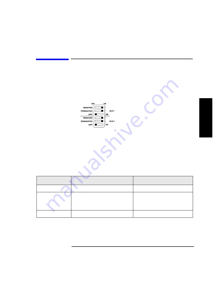
The SCSI interface mode switch, shown below, is on the rear panel between 
the bus 1 and bus 2 SCSI ports.

Figure 2-1

SCSI Interface Mode Switch

To set the SCSI interface mode switch:

1. Determine how to connect the library according to:

Number of drives in the library and drive type (only DLT4000 drives 
are supported as daisy-chained)

Number of SCSI cards

2. Set the SCSI interface mode switch.

Table 2-3

SCSI Interface Mode Switch Settings

Setting

Purpose

Set to

Term Pwr

Sends power to the terminator

ON in most installations

Termination

Terminates the SCSI bus; functions 
the same as a physical terminator

ON if one port on the bus is open

OFF if both ports on the bus are 
connected to a cable

DIFF/SE

Specifies interface mode

DIFF for differential

Summary of Contents for Surestore Tape Library Model 2/15

Page 1: ...HP DLT Tape Library 15 Slot User s Guide Model A4851A November 1997 Printed in United States Copyright 1997 Hewlett Packard Company DLTtape is a trademark of Quantum Corporation ...

Page 2: ...ied warranties of merchantability and fitness for a particular purpose Hewlett Packard shall not be liable for errors contained herein or for incidental or consequential damages in connection with the furnishing performance or use of this material See Appendix B for important safety and regulatory information Printing History New editions of this manual incorporate all material updated since the p...

Page 3: ...edure or practice that could result in personal injury if not correctly performed Do not proceed beyond this box until you fully understand and meet the indicated conditions This warning symbol on a product label indicates that personal injury could result if the product is used improperly and that more detailed information is given in the installation and or user manuals Font Used for Italics Doc...

Page 4: ...iv ...

Page 5: ...14 2 Library Installation Overview 2 2 Step 1 Choose a Location 2 3 Step 2 Prepare Components 2 4 Step 3 Install the Host SCSI Card s 2 5 Step 4 Mount the Library in a Rack 2 6 Step 5 Set the SCSI Interface Mode Switch 2 7 Step 6 Connect Library to Host 2 9 Routing SCSI and Power Cables on Rack Mounted Libraries 2 10 Step 7 Connect Power 2 13 Step 8 Configure the Host 2 14 Moving or Shipping the L...

Page 6: ...ministration Menu Password 4 8 Specifying SCSI Addresses 4 9 Viewing Current SCSI Address Settings 4 10 Setting SCSI Addresses 4 10 Interpreting SCSI Bus Status Indicator LEDs 4 12 Loading Cartridges Into the Library 4 13 Inserting Removing Cartridges with Software 4 13 Keeping Cartridges in the Magazine 4 13 Loading Tapes 4 14 Removing Tape Cartridges from the Library 4 17 Viewing Cartridge Bar C...

Page 7: ...Overview B 2 Safety Information B 3 Laser Safety B 3 CDRH Regulations USA Only B 3 Regulatory Information B 4 FCC Radio Frequency Interference Statement USA Only B 4 EC Radio Frequency Interference Statement Europe Only B 4 United Kingdom Telecommunications Act 1984 B 4 EC Declaration of Conformity B 5 Herstellerbescheinigung B 6 English Translation of German Sound Emission Directive B 6 Turvallis...

Page 8: ...viii Contents ...

Page 9: ...12 Figure 2 5 Front Access Door 2 12 Figure 3 1 Proper Label Position 3 4 Figure 3 2 Write Protect Button Settings 3 5 Figure 3 3 Magazine Label Position 3 7 Figure 4 1 Tape Library Control Panel 4 3 Figure 4 2 Control Panel Menu Options 4 6 Figure 4 3 Opening the Front Access Door 4 15 Figure 4 4 Loading Tape Cartridges into the Magazine 4 15 Figure 4 5 Inserting Magazines 4 16 Figure 4 6 Opening...

Page 10: ...x Figures ...

Page 11: ... Table 2 3 SCSI Interface Mode Switch Settings 2 7 Table 2 4 Library Connection Options 2 8 Table 3 1 Supported Tape Types 3 3 Table 3 2 Tape Cartridge Maintenance 3 6 Table 4 1 SCSI ID Options 4 9 Table 4 2 Default SCSI Address Settings 4 9 Table 4 3 SCSI Status Indicators 4 12 Table 4 4 Drive Cleaning Issues Relating to Tape Cartridges 4 23 Table 4 5 Configuration Options 4 25 Table 4 6 Informat...

Page 12: ...xii Tables ...

Page 13: ...1 1 1 Product Description ...

Page 14: ...1 2 Product Description Overview Overview HP DLT Tape Library Product Matrix Supported Platforms Library Rear Panel Features Specifications ...

Page 15: ...DLT Tape Library Fully automated State of the art patented HP robotics Industry leading data availability Industrial strength durability User maintenance free library system Available configurations are described in Table 1 1 on page 1 4 Figure 1 1 HP DLT Tape Library ...

Page 16: ... A6K 701 One DLT7000 15 DLT7000 2 15 A4851A A6K 702 Two DLT7000 15 Field Rack Libraries DLT4000 1 15 A4851A A6L 401 One DLT4000 15 DLT4000 2 15 A4851A A6L 402 Two DLT4000 15 DLT7000 1 15 A4851A A6L 701 One DLT7000 15 DLT7000 2 15 A4851A A6L 702 Two DLT7000 15 Kit HP Product Number Upgrades Converts To DLT4000 Upgrade Kit A4842A DLT4000 1 15 DLT4000 2 15 DLT7000 Upgrade Conversion Kit A4843A DLT400...

Page 17: ...ected to an HP Fibre Channel SCSI multiplexer HP A3308A and HP A3511A Z and thereby benefit from Fibre Channel speed and distance The FC SCSI multiplexer is supported on K T and V platforms running HP UX 10 20 TFC or higher Consult an HP sales representative for the latest information Servers D Class E Class K Class Nova T Class V Class Workstation J Class ...

Page 18: ...I interface mode switches specify term power termination and differential settings for each SCSI bus 3 Bus 2 SCSI ports single ended and differential Drive 2 is internally connected to Bus 2 two drive library only 4 SCSI bus status indicator label explains the SCSI bus status indicators 5 Power connector connects the power cord to the library 6 SCSI bus indicators indicate SCSI bus status Each SCS...

Page 19: ... mode 5 2 MB second compressed 2 1 typical 10 0 MB second Average access time 68 seconds 60 seconds Rewind 45 seconds average 90 seconds maximum 60 seconds average 120 seconds maximum Loading time to BOT for previously written tape 48 seconds average 48 seconds average Unloading time to BOT 17 seconds average 17 seconds average External Interface 8 bit SCSI 2 differential 16 bit fast wide SCSI 2 d...

Page 20: ...x 106 bytes minimum 1 x 106 bytes minimum Hard read error rate 1 x 1017 bytes minimum 1 x 1017 bytes minimum Hard write error rate Not allowed Not allowed Undetected error rate 1 x 1030 bits read 1 x 1027 bits read MTBF 80 000 hours 200 000 hours Head life 10 000 hours 30 000 hours Power Specifications Total Power consumption 22 W average 33 W maximum 37 W average 47 W maximum 5 volt supply 5 0 V ...

Page 21: ... depth 5 1 4 in height with modified depth Height 3 25 in w o bezel 3 25 in w o bezel Width 5 7 in behind bezel 5 7 in behind bezel Depth 9 0 in measured from back of front bezel 9 0 in measured from back of front bezel Weight net 6 lb 7 oz 6 lb 7 oz Table 1 5 DLT Drive Specifications Continued Characteristic DLT4000 DLT7000 ...

Page 22: ...00 000 hours MSBF robotics 1 million swaps Preventive maintenance None required Power Requirements Total power consumption 140 W typical NOTE After 30 minutes of non operation 150 W maximum the library operates in reduced power mode Line voltage 100 127 200 240 Vac Line frequency 50 to 60 Hz Physical Specifications Height 348 mm 13 7 in w o bezel 353 4 mm 13 9 in with bezel Width 442 mm 17 4 in w ...

Page 23: ...mpressed 30 GB 2 1 typical compression 40 70 GB 2 1 typical compression Basic description 0 5 in metal particle 0 5 in metal particle Tape length 1167 ft 1778 ft Cartridge dimensions 4 1 in x 4 1 in x 1 0 in 4 1 in x 4 1 in x 1 0 in Shelf life 30 years min 20o C 40 RH non condensing 30 years min 20o C 40 RH non condensing Usage 1 000 000 passes min 10 000 loads unloads min 1 000 000 passes min 10 ...

Page 24: ...to 90 RH Storage shipment 40 to 66 C drive 16 to 32 C tape 10 to 95 RH 30 to 60 C 14 consecutive days Archive 18 to 28 C 40 to 60 RH 30 to 60 C 14 consecutive days Gradient 10 C hour 15 C hour Altitude Operating 0 to 30 000 ft N A Non operating 0 to 50 000 ft N A Shock Operating 60 half sine shock impulses of 5 g s for 11 sec in 3 axes 4 in half sine edge drop 4 faces Non operating half sine 55 g ...

Page 25: ...Non operating swept sine 5 10 Hz 0 5 g peak 10 50 Hz 1 g peak 50 500 Hz 3 g peak 5 500 5 Hz 1 2 octave minute in 6 axes 0 5 grms 0 to peak Non operating random packaged 2 200 Hz 1 5 grms 6 axes dwell 30 m 1 49 grms top to bottom Non operating swept sine packaged 5 150 Hz 0 5 g peak 5 150 5 Hz 1 2 oct min 6 axes with dwell at lowest natural resonance in each axes 0 5 G 0 pk 3 200 3 Hz 1 oct min 1 a...

Page 26: ... 950 Electromagnetic emissions EN55022 CISPR 22 Class B EN50082 1 EN55024 2 IEC 1000 4 2 4kV CD 8kV AD EN55024 3 IEC 1000 4 3 3 V m EN55024 4 IEC 801 4 1kV Peak Power lines 0 5 kV Signal lines FCC 47 CFR Part 15 Class B VCCI Class B EN61000 3 2 IEC 1000 3 2 EN61000 3 3 IEC 1000 3 3 Laser EN60825 1994 IEC 825 1993 A1 Laser Class 1 ...

Page 27: ...2 1 2 Library Installation ...

Page 28: ... Install the host SCSI card s 4 Mount the library in a rack rack mount configuration only 5 Set the SCSI interface mode switch 6 Connect the library to the host 7 Connect power 8 Configure the host This chapter also explains how to move or ship the library NOTE Installation must be performed by HP qualified personnel ...

Page 29: ...acks of supplies that collect dust and smoke filled rooms CAUTION Excessive dust and debris can damage tapes and tape drives Adequate clearance Standalone configuration free standing or against a wall desk Back 56 cm 22 in for cooling and service Front 86 cm 34 in for operator access Sides56 cm 22 in for removal of the external cover Rack mount configuration Back Allow adequate room to open the re...

Page 30: ...ard s Required number of cards installed in host depends on library configuration Connect drives and robotics controller to differential fast wide SCSI cards SCSI cables Required number of cables 68 pin is one per drive and one for the robotics controller Maximum cable length total is 25 meters Power cord Power cord is included with library Rack mount kit Rack mount kit is included with rack mount...

Page 31: ...tallation Step 3 Install the Host SCSI Card s Library Installation Step 3 Install the Host SCSI Card s Refer to the host user manual and the SCSI card installation instructions for information on installing SCSI cards ...

Page 32: ...2 6 Library Installation Step 4 Mount the Library in a Rack Step 4 Mount the Library in a Rack For rack mount configurations refer to the installation instructions included in the rack mount kit ...

Page 33: ... how to connect the library according to Number of drives in the library and drive type only DLT4000 drives are supported as daisy chained Number of SCSI cards 2 Set the SCSI interface mode switch Table 2 3 SCSI Interface Mode Switch Settings Setting Purpose Set to Term Pwr Sends power to the terminator ON in most installations Termination Terminates the SCSI bus functions the same as a physical t...

Page 34: ...ace mode switch settings Table 2 4 Library Connection Options Configuration Cabling SCSI Interface Mode Switch Settings One Drive Library Two Drive Library Daisy chained DLT4000 drives only Minimum host I O slots used Two Drive Library Bus 1 and bus 2 connect to separate SCSI cards Maximum performance Additional card and cable required bus 2 not used ...

Page 35: ...e connection diagram on page 2 8 Using this configuration connect the library to the host Make sure The differential port is used The last device in the SCSI bus is terminated 3 Make sure the power switch on the library front panel is switched off 0 position 4 Plug the power cord into the power port on the back of the library Stand alone installations Go to Step 7 Connect Power on page 2 13 Rack m...

Page 36: ...I power cables through the strain relief bracket a Squeeze the two plastic ends of the cable strain relief bracket together b Pull off the plastic strain relief clamp c Route the SCSI cable s and the power cord through the cable strain relief bracket d Slide the strain relief clamp back onto the bracket e Attach a cable tie included in the rack mount kit to the SCSI and power cables about eight in...

Page 37: ...brary if the rack tips over 3 Use the key to open the front access door Remove the two screws that secure the library to the rack Figure 2 3 Front Access Door 4 Slide the library out of the rack so that it is in the fully extended position 5 Gently pull the SCSI and power cables back toward the rear of the rack Use a cable tie to secure them to the rail at the back of the rack The cable tie should...

Page 38: ... to the rail just above the slide mounting bracket Clip off the ends of all four cable ties Figure 2 4 Secured SCSI and Power Cables 7 Close the back door on the rack 8 Push the library back into the rack 9 Open the front access door Replace the two screws that secure the library to the rack then relock the door Figure 2 5 Front Access Door ...

Page 39: ...and then NOT READY and INVENTORY CHECK display alternately After the power on test completes in about 3 minutes the drive status information displays See Understanding the Display Window on page 4 4 NOTE If the drive status information does not display the power on test was not successful and DEVICE FAILED displays See resolving Other Problems on page 4 43 3 Turn on the host system ...

Page 40: ... Step 8 Configure the Host Step 8 Configure the Host An HP qualified service representative must configure the library on the host This procedure includes installing drives creating device files and verifying the configuration ...

Page 41: ...how to unmount tape cartridges 3 Verify that all drives in the library are empty displays after the drive number if the drive is empty displays after the drive number if the drive is full If the drives are full empty them before shipping the library For instructions refer to the software documentation your host system uses to manage the library 4 Switch off the power switch on the library front pa...

Page 42: ...resentative for assistance in getting replacement handles d Remove the three 8 32 screws on each side of the library that secure the library to the rack slides 7 IMPORTANT two people needed With a person on each side of the library lift the library onto a cart 8 Transport the library To move the library a short distance roll the cart to the new location To ship the library repackage the library in...

Page 43: ...3 1 3 Tape Cartridges ...

Page 44: ...3 2 Tape Cartridges Overview Overview Choosing Tape Cartridges Labeling Tape Cartridges Write Protecting Tape Cartridges Maintaining Tape Cartridges Labeling Bulk Load Magazines ...

Page 45: ...s are supported Table 3 1 Supported Tape Types NOTE Hewlett Packard recommends using the HP DLTtape IV Data Cartridge See Appendix A for ordering information Cartridge Type Available Densities DLTtape IV Data Cartridge 20 GBytes DLT4000 drive 35 GBytes DLT7000 drive DLTtape III XT Data Cartridge 15 GBytes ...

Page 46: ...torage purpose such as backup old version of operating system If the host software does not keep track of this information create a method of doing so Slide the label into the slot on the face of the cartridge as illustrated in Figure 3 1 NOTE If bar code labels are not used and the Barcode On Off configuration is set to On the Inventory Check test performance can be significantly affected This te...

Page 47: ...protect switch Left to prevent data from being written to the cartridge The orange indicator on the cartridge can be seen when the write protect switch is in the ON position see A in Figure 3 2 Right to allow data to be written to the cartridge The orange indicator on the cartridge cannot be seen when the write protect switch is in the OFF position see B in Figure 3 2 With the write protect switch...

Page 48: ...dges to any unnecessary physical shock Open cartridges lid exposing the tape to possible contamination or physical damage Touch the tape surface Take cartridges apart Use graphite pencils water soluble felt pens or other debris producing writing instruments to label cartridges Erase a label replace it instead Store cartridges in a clean safe place in their protective plastic containers when not in...

Page 49: ...s can be labeled in a manner similar to tape cartridges To label bulk load magazines 1 Clean the magazine surface with isopropyl alcohol optional but recommended 2 Remove the adhesive backing from the label pouch 3 Apply the pouch to the magazine 4 Slide the label into the pouch Figure 3 3 Magazine Label Position ...

Page 50: ...3 8 Tape Cartridges Labeling Bulk Load Magazines ...

Page 51: ...4 1 4 Library Operation ...

Page 52: ... New Administration Menu Password Specifying SCSI Addresses Setting Configuration Options Retrieving Performance Information Running an Internal Test Using Online Repair Loading Cartridges Into the Library Removing Tape Cartridges from the Library Cleaning the Tape Drives Clearing a Drive Cleaning Error Viewing Cartridge Bar Code Labels Troubleshooting ...

Page 53: ...d by one When held continuously the options scroll quickly ENTER selects the displayed option 2 Activity light indicates the following Steady Green power is on Flashing Green a tape cartridge is being accessed Amber fault indicator 3 16 Character Display displays information about the current operation or drive status An asterisk indicates there is a menu beneath the option Press ENTER to access t...

Page 54: ...s The drive is full The drive is empty The drive needs to be cleaned The tape cartridge in the drive is write protected Blank The drive is offline Activity Indicators The activity light flashes during the following operations Information is being written to the tape in the drive Information is being read from the tape in the drive The tape in the drive is being searched backward or is rewinding Th...

Page 55: ...lay the option s selections Press PREV or NEXT to display other available options First Level Options Second Level Options RELEASE DOOR Allows the rear access door to be unlocked VIEW BAR CODES Displays the bar code labels on each tape cartridge by slot number ADMIN Accesses second level options INFO Displays performance information stored in the library TEST Runs internal library tests CONFIG Cus...

Page 56: ...gs available as under HARD ERRORS RESTORE DEFAULTS CLEAR ODOMETERS STARWARS ON OFF NEW PASSWORD SCSI LOG ON OFF SECURE ON OFF POWER SECURE ON OFF REP RECOVERED ON OFF CONF40 ON OFF LIB ID DRIVE 1 ID DRIVE 2 ID SET IDs DRIVE 1 ID DRIVE 2 ID UPDATE IDs NOW RELEASE DOOR PREV NEXT CLEAN DRIVES CLEAN DRIVE 1 CLEAN DRIVE 2 CLEAN DRIVE ALL ENTER ENTER ENTER ENTER ENTER ENTER SEL CLEAN CART or OVERRIDE DO...

Page 57: ... security code to the factory setting To enter the password 1 Verify that the drive status displays if not press CANCEL until it does 2 Press NEXT until ADMIN displays then press ENTER 3 PSWD 000 000 000 displays and the first set of zeros flashes Press ENTER to accept this number if no password has been set or press NEXT or PREV until the set number displays Press ENTER 4 The middle set of zeros ...

Page 58: ...en press ENTER 4 NEW 000 000 000 displays and the first set of zeros flashes Press NEXT or PREV to display the desired first part of the password then press ENTER 5 The second set of zeros flashes Press NEXT or PREV to display the desired second part of the password then press ENTER 6 The last set of zeros flashes Press NEXT or PREV to display the desired third part of the password then press ENTE...

Page 59: ...sed library If connecting to a narrow host use only addresses 0 to 7 Table 4 1 SCSI ID Options Table 4 2 Default SCSI Address Settings Option Purpose Explained in SET IDs Assigns individual SCSI IDs to each drive and the robotics controller Setting SCSI Addresses on page 4 10 VIEW IDs Displays the current drive and robotics controller settings Viewing Current SCSI Addresses on page 4 10 DEVICE SCS...

Page 60: ...nd its associated BUS Press NEXT or PREV to scroll through the current address settings a Press CANCEL until the next operation to perform displays or until the drive status library ready state displays Setting SCSI Addresses 1 2 ADMIN PSWD 000 000 000 SCSI IDs SET IDs A SCSI address is required for the robotics controller and each drive For more information see Table 4 2 Default SCSI Address Sett...

Page 61: ...s If the new settings do not conflict with other SCSI IDs on the bus SCSI IDs displays If the new settings conflict with other IDs on the SCSI bus CONFLICT ABORTED displays briefly then SET IDs displays Any changes entered are lost and previous steps must be repeated to set a new address If any buses are daisy chained together make sure the SCSI IDs are different for each device on the bus If a se...

Page 62: ... 4 3 SCSI Status Indicators Indication Status Steady green Port active and OK Internal on board termination enabled Flashing green Port active and OK Internal on board termination disabled No light Port not active or not configured Flashing red Bus mismatch or loss of external termination power Flashing yellow Bus offline for online drive replacement ...

Page 63: ...ibrary DO NOT use excessive force when inserting the magazines This can cause the magazine latching mechanisms to fail DO NOT insert magazines when the library power is turned off During normal library operation the cartridge release button on top of the magazine is pushed down by a special mechanism inside the library This unlocks the cartridges allowing them to be inserted and removed from the s...

Page 64: ...EASED displays See the note below If an error message displays see Resolving Other Problems on page 4 43 NOTE The drive s must be empty before the access door can be released If the drive s are not empty EMPTY DRIVES NO displays Press NEXT or PREV until EMPTY DRIVES YES displays then press ENTER NOTE Some security configurations may prevent the access door from being released If a security option ...

Page 65: ... not let the door fall open The door straps may be damaged Figure 4 3 Opening the Front Access Door 7 Insert up to five tape cartridges into a magazine so that the tape brand name printed on the top of the cartridge is facing up and the tape label is facing out The tapes should click into place Figure 4 4 Loading Tape Cartridges into the Magazine ...

Page 66: ...oor using the key lock Make sure the door is shut completely NOTE The library Inventory Check test runs when the access door is closed so that an inventory of tape bar code labels and storage slot locations can be stored into library memory This process takes about one minute The test fails if the door is not completely shut WARNING Do not attempt to disable the interlocks If the library is operat...

Page 67: ...rary are empty displays after the drive number if the drive is empty displays after the drive number if the drive is full 3 Press NEXT or PREV until RELEASE DOOR displays 4 Press ENTER DOOR RELEASED displays See the following note If an error message displays see Resolving Other Problems on page 4 43 NOTE The drive s must be empty before the access door can be released If the drive s are not empty...

Page 68: ...l open Damage to the door straps may occur Figure 4 6 Opening the Front Access Door 6 Remove the desired magazine by pushing the button at the top of the magazine handle see Figure 4 7 and pulling out the magazine Figure 4 7 Removing Magazines 7 If necessary remove tapes from the magazine Press the button on top of the magazine then pull out the tape ...

Page 69: ...e door open the user can be exposed to Class II laser light emitted from the bar code reader 8 Shut and lock the access door using the key lock Make sure the door is shut completely NOTE The library Inventory Check test runs when the access door is completely closed so that an inventory of tape bar code labels and storage slot locations can be stored into library memory This process takes about on...

Page 70: ...does 2 Press NEXT until VIEW BAR CODES displays then press ENTER SLOT displays represents the bar code information and represents the first storage slot that contains a bar coded tape cartridge NOTE If there are no bar coded tape cartridges in the library LIBRARY EMPTY displays briefly then VIEW BAR CODES displays Press CANCEL to return to the drive status indicators ready state 3 Press NEXT or PR...

Page 71: ...splays if not press CANCEL until it does 2 Make sure all drives are empty displays after the drive number To empty the drives refer to the documentation for the software package 3 Press NEXT until ADMIN displays then press ENTER 4 Enter the three part numerical password see Entering the Administration Menu Password on page 4 7 5 INFO displays Press NEXT until CLEAN DRIVES displays then press ENTER...

Page 72: ...N CART displays briefly then CLEAN FAIL displays Press CANCEL to twice to return to the ready state Check the bulk load magazines in the library to locate the cleaning cartridge If no cleaning cartridge is present insert one into an available slot In the event of a drive error such as a serial communications failure FAILED displays and the CLEAN DRIVES menu displays CLEANING DRV displays is the nu...

Page 73: ...and a drive cleaning message is received Dust from frequent tape loads and unloads has most likely built up on the tape cartridge and was deposited on the drive head 1 Clean the outside of the tape cartridge using a damp cloth 2 Clean the tape drive using the tape drive cleaning procedure on page 4 21 An older frequently used tape causes a cleaning message to be displayed for the second time The t...

Page 74: ... the Administration Menu Password on page 4 7 4 INFO displays Press NEXT until CONFIG displays then press ENTER 5 Press NEXT or PREV until the name of the configuration to set displays then press ENTER If the configuration has multiple settings the current setting flashes Otherwise the configuration option is set and a confirmation message displays Configuration options are described on the follow...

Page 75: ...sonnel only Set to ON during normal operation ON Library runs with the vertical sensors enabled OFF Library runs with the vertical sensors disabled ON NEW PASSWORD Changes the numerical password required to access ADMIN options configurations tests and information logs To change the password see Setting a New Administration Menu Password on page 4 8 SECURE ON OFF Toggles between ON and OFF If the ...

Page 76: ...only Do not attempt to use this configuration to do so may result in a service call BARCODE ON OFF ON Bar codes and slot locations are stored into library memory when the front access door is closed and the Inventory Check test automatically runs OFF Bar codes are not recorded when the Inventory Check test runs ON Table 4 5 Configuration Options Continued Config Name Description Default ...

Page 77: ...EXT until the name of the log to access displays then press ENTER An asterisk indicates that there are more choices beneath the displayed choice 6 Press CANCEL to return to the drive status ready state Table 4 6 Information Logs Problem Solution REVISION Library firmware revision number LIB ODOMETERS Press ENTER to select the odometer logs HOURS Number of operation hours time during which power wa...

Page 78: ...plete Returns either NO HARD ENTRIES or ENTRY There may be multiple hard error numbers Press ENTER to view the log for the currently displayed error or press NEXT to select the next error SOFT ERROR Log entries are described after RECOVERY ERROR in this table Log of recovered errors and commands successfully completed Returns either NO SOFT ENTRIES or ENTRY There may be multiple soft error numbers...

Page 79: ...of the failure FRU 1 Field replaceable unit most likely to be at fault FRU 2 Field replaceable unit second most likely to be at fault FRU 3 Field replaceable unit third most likely to be at fault MOTION name name indicates the type of movements taking place at the time of the failure EXCHANGE MOVE POSITIONINIT ELEMREZERO ROTATEDIAGNOSTIC RESTORE SOURCE Element number to which the source refers Val...

Page 80: ... MICROMOVE 1 First library micro move for the original move command issued before the failure MICROMOVE 2 Second library micro move for the original move command issued before the failure MICROMOVE 3 Third library micro move for the original move command issued before the failure MICROMOVE 4 Fourth library micro move for the original move command issued before the failure MICROMOVE 5 Fifth library...

Page 81: ...ome diagnostic tests can only be run through the SCSI interface Refer to Digital Linear Tape Drive and Library SCSI 2 Command Reference HP part number 5960 7674 for information about these tests To run self diagnostic tests 1 Verify that the drive status displays if not press CANCEL until it does 2 Press NEXT until ADMIN displays then press ENTER 3 Enter the three part numerical password see Enter...

Page 82: ... is moved from a randomly chosen full slot to a randomly chosen drive If the drives are full a tape cartridge is moved from a randomly chosen drive to a randomly chosen storage slot It then moves the cartridge back to its original location This test displays FAIL if there are no cartridges in the library or if all storage slots are full The transport and mailslot must be empty IO MAGAZINE Makes a ...

Page 83: ...r test loop EMPTY DRIVES Service personnel use only Do not run this test if the library contains cartridges containing actual customer data Moves cartridges out of the drive mechanisms and returns them to their home storage slot locations if the locations are known otherwise the cartridges are placed into the first available empty storage slot EMPTY PICKER Service personnel use only Do not run thi...

Page 84: ... to another Displays ON or OFF If OFF displays the sensor is blocked This display is automatically updated if the sensor status changes Requires the use of one tape cartridge SENSORS MAGAZINE The display shows M1 1 M2 1 M3 1 Each 1 indicates that the caddy is in place If a 0 displays the caddy has not been inserted into the library This display is automatically updated if the sensor status changes...

Page 85: ...the administrator can attempt to recover data from the damaged tape CAUTION The library drive mechanism s are inactive while this option is in use To use this option to clear a drive cleaning error 1 With CLEAN DRV displayed press CANCEL until the drive status displays is the drive number containing the damaged tape 2 Press NEXT until ADMIN displays then press ENTER 3 Enter the three part numerica...

Page 86: ...ss ENTER 11 DRV OFF FAILED displays where is the drive number and OFF FAILED is flashing 12 Press NEXT until DRV ON GOOD displays then press ENTER 13 SETTING UP DRIVE displays briefly while the drive communication tests run then CHANGE CONFIRMED displays briefly then ONLINE REPAIR displays 14 Press CANCEL twice to return to the drive numbers and status indicators ready state 15 Try reading the dam...

Page 87: ...ress ENTER DRIVE POWER displays 5 Press NEXT or PREV until DRIVE STATUS displays then press ENTER DRV 1 ON GOOD displays If the damaged tape is in drive 1 press ENTER If the damaged tape is in drive 2 press NEXT until DRV 2 ON GOOD displays then press ENTER DRV ON GOOD displays where is the drive number and ON GOOD is flashing 6 Press NEXT until DRV OFF FAILED displays then press ENTER 7 CHANGE CO...

Page 88: ...n tests run then CHANGE CONFIRMED displays briefly then ONLINE REPAIR displays 14 Press CANCEL twice to return to the drive numbers and status indicators ready state 15 Try reading the damaged tape again If the tape can be read back up data from the damaged cartridge to another tape cartridge and discard the damaged one ...

Page 89: ...ols exist Not all are supported on all devices The following table provides a brief description of the types of tools Table 4 8 Support Tool Characteristics Tool Type Description Self maintainer license required Supported for Drives Robotics Information tools Provides quick access to the most useful information about a device Verifiers Quickly verifies that a particular device is properly connecte...

Page 90: ... Changer 2 Choose a support tool for example a verifier to run on the selected device Results appear on the system map for example on xstm a green icon indicates that a device successfully passed the test 3 If the device fails see the device Failure Log for the cause of the failure and suggested actions 4 If a test result is anything other than Successful or Failure look at the Test Activity Log f...

Page 91: ...ct ID product revision level and firmware revision level DRIVE INFO Displays power on hours and tape motion hours Tests TAPE VALIDATE Reads a suspect tape until either an error is detected or end of data is encountered SELFTEST Executes the DLT device s built in diagnostic selftest TUR Sends a Test Unit Ready command Utility TAPE COPY Performs a tape to tape copy UNLOAD TAPE Performs an unload seq...

Page 92: ... Data Transfer or Import Export Element MODE SENSE Displays the Device Capabilities or Element Address mode page Tests TEST UNIT READY Sends a Test Unit Ready command SELFTEST Runs the power up selftest which calibrates the picker and inventories the library WELLNESS Runs the power up selftest then performs the Exercise Mechanism test see below EXERCISE MECHANISM Tests the picker s ability to inte...

Page 93: ...ICKER Unloads the picker The cartridge is returned to its home location if it is known otherwise to the first available empty slot VERTICAL ENCODER Moves the picker up and down its full course of travel Utility REZERO Initialize robotics controller POSITION TO ELEMENT Position picker in front of a selected slot MOVE MEDIUM Move medium from a selected source slot to a selected destination slot EXCH...

Page 94: ...rary Press the power switch off and then on again See the caution note at the end of this table If the power on test continues to fail press ENTER write down the displayed error code and call a service representative for assistance DEVICE FAILED displays Hardware Error 61 External SCSI cables is reported Make sure that only differential SCSI device type is used on the SCSI bus Verify that the libr...

Page 95: ...he magazine again when the drive numbers and status indicators are displayed See the caution note at the end of this table If SECURITY ENABLED displays a security option has been set that prevents cartridges from being loaded into or removed from the library See Setting Configuration Options on page 4 24 If TRANSPORT FULL displays the cartridge transport mechanism already contains a tape cartridge...

Page 96: ...cartridge removal See SECURE ON OFF in the list of configurations found in Setting Configuration Options on page 4 24 Started a test and need to stop Press CANCEL The current test loop continues until finished then the test stops DO INVENTORY TEST displays initialize element status Power cycle the library by pressing the power switch off and then on again See the caution note at the end of this ta...

Page 97: ...A 1 A Supplies and Accessories ...

Page 98: ...aler or sales office or by phoning or writing HP Direct Call 1 800 752 0900 for the location of your nearest authorized Hewlett Packard dealer To phone HP Direct call 1 800 538 8787 or write to HP Direct at the following address HP Direct Hewlett Packard attn Mail Order P O Box 1145 Roseville California 95678 See Table A 1 for a list of basic supplies and accessories ...

Page 99: ...GByte native capacity C5141F HP DLTtape III XT Data Cartridge 15 GByte native capacity C5141A Cleaning Tape Cartridge C5142A Bar Code Labels Bar code labels are not available through Hewlett Packard but can be ordered through other companies see sample labels shipped in the accessories kit When ordering make sure the bar code labels meet the following specifications Message 6 character 2 alpha 4 n...

Page 100: ...les for V Class 68 pin to 68 pin 5m SCSI cable high density with thumb screws to high density with thumb screws m m with inline terminator for V Class A4801 63004 10m SCSI cable high density with thumb screws to high density with thumb screws m m with inline terminator for V Class A4801 63002 SCSI Cables 50 pin to 68 pin 1m SCSI cable high density with thumb screws to high density with thumb screw...

Page 101: ...e upgrade kit upgrades a DLT4000 1 15 to DLT4000 2 15 A4842A DLT 7000 1 Drive upgrade conversion kit upgrades a DLT4000 1 15 to DLT7000 2 15 orDLT4000 1 15 to DLT7000 2 15 A4843A User s Guide replacement additional A4851 90000 Table A 1 Basic Supplies and Accessories Continued Item HP Product Number HP Part Number ...

Page 102: ...A 6 Supplies and Accessories Supplies and Accessories ...

Page 103: ...B 1 B Safety and Regulatory Information ...

Page 104: ...B 2 Safety and Regulatory Information Overview Overview This section contains important safety and regulatory information for the United States Finland Sweden European Union and Japan ...

Page 105: ... U S Food and Drug Administration implemented regulations for laser products on August 2 1976 These regulations apply to laser products manufactured from August 1 1976 Compliance is mandatory for products marketed in the United States The labels and artwork shown below indicate compliance with CDRH regulations and must be attached to laser products marketed in the United States WARNING Use of cont...

Page 106: ...erence to radio or television reception which can be determined by turning the equipment off and on the user is encouraged to try to correct the interference by one or more of the following measures Reorient or relocate the receiving antenna Increase the separation between the equipment and receiver Connect the equipment into an outlet on a circuit different from that to which the receiver is conn...

Page 107: ...B 5 Safety and Regulatory Information Regulatory Information Safety and Regula tory Information EC Declaration of Conformity ...

Page 108: ...ar 1991 Schalldruckpegel Lp 70 dB A am arbeitsplatz normaler betrieb nach ISO 7779 1988 EN 27779 1991 Typprüfung English Translation of German Sound Emission Directive This statement is provided to comply with the requirements of the German Sound Emission Directive from 18 January 1991 Sound pressure Lp 70 dB A at operator position normal operation according to ISO 7779 1988 EN 27779 1991 type tes...

Page 109: ...nen muulla kuin käyttöohjeessa mainitulla tavalla saattaa altistaa käyttäjän turvallisuusluokan 1 ylittävälle lasersäteilylle VARNING Om apparaten används på annat sätt än i bruksanvisning specificerats kan användaren utsättas för laserstrålning som överskrider gränsen för laserklass 1 HUOLTO HP DLT Tape Library nauhamuistiasemien sisällä ei ole käyttäjän huollettavissa olevia kohteita Laitteen sa...

Page 110: ...aser bar code reader installed inside the tape library units doesn t cause any hazard to the user The laser safety class of the libraries was defined in accordance with the standard EN 60825 1 1994 WARNING The use of the product otherwise than specified in the user s manual may expose the user to laser radiation exceeding safety class 1 SERVICE There are no user serviceable parts inside the HP DLT...

Page 111: ...safety class Class 2 laser Japanese VCCI Statement English Translation of Japanese VCCI Statement This equipment is in the Class B category information technology equipment based on the rules of Voluntary Control Council For Interference by Information Technology Equipment VCCI Although aimed for residential area operation radio interference may be caused when used near a radio or TV receiver Read...

Page 112: ...B 10 Safety and Regulatory Information Regulatory Information ...

Page 113: ...rary features 1 3 performance information 4 27 removing tapes 4 17 shipping 2 15 location for tape library placement of library 2 3 M magazines labeling 3 7 menu tree 4 6 messages display window 4 4 mounting the library rackmounting instructions 2 6 moving the library 2 15 O ordering supplies A 2 P password entering 4 7 performance logs displaying 4 27 power cables routing 2 10 power switch turnin...

Page 114: ...s choosing 3 3 cleaning issues 4 23 ejecting 4 17 labeling 3 4 maintenance of 3 6 ordering A 3 write protecting 3 5 tapes drives cleaning 4 23 temperature operating 2 3 troubleshooting 4 43 type styles in this book iii V voltage 2 3 ...

Reviews: