background image

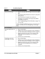
164 Removing and Replacing Drive Modules

Chapter 5

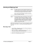
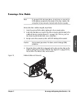
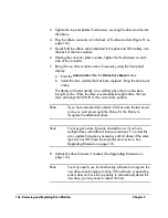
5.  Lay the connector assembly to the side, allowing the external cables to 

hang from the connection(s). Do not disconnect external cables from the 

connector plate.

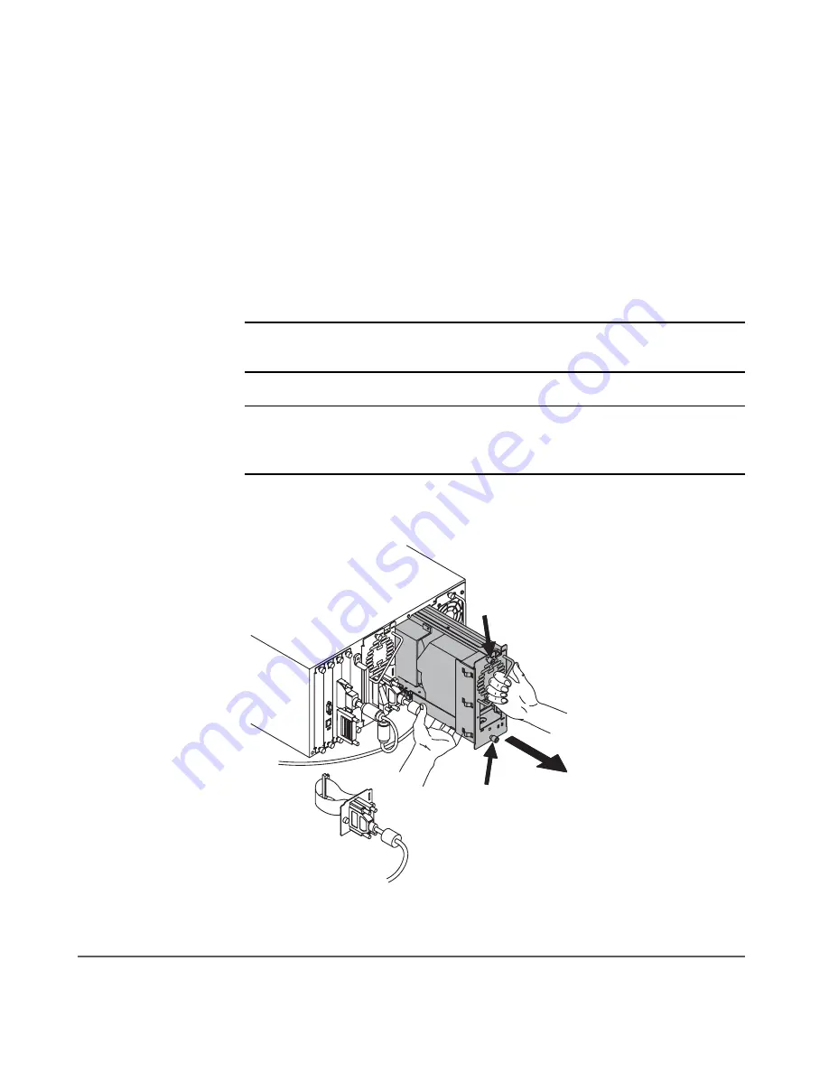
6.  Loosen the top and bottom thumbscrews on the drive module (

Figure 52


on page 164).

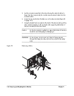
7.  Using the handle that is mounted on the back of the drive module, pull the 

drive module straight out with one hand while supporting the bottom of 

the drive module with the other hand.

Caution

As the drive module is pulled out, support the bottom of the drive 

module to avoid dropping or damaging it.

WARNING

To avoid injury, do not insert your hand or foreign objects 

through the empty drive bay and into the vertical lift assembly 

area.

Figure 52


Removing a Drive

Summary of Contents for Surestore E Tape Library Model 2/20

Page 1: ...hp surestore tape library 2 20 4 40 6 60 8 80 and 10 100 series user s guide ...

Page 2: ......

Page 3: ...2 20 4 40 6 60 8 80 and 10 100 series hp surestore tape library user guide Product Number C9521 90002 Edition 5 June 2002 2002 Hewlett Packard Company ...

Page 4: ...hat could result in personal injury if not correctly performed Do not proceed until you fully understand and meet the required conditions In This Manual Chapter 1 Installing the Library Describes how to install rackmount connect and power on the library Chapter 2 Operating the Library Describes the front panel menu structure menu trees and drive and tape operations Chapter 3 Library Administration...

Page 5: ...ront panel information Edition 4 December 2001 C9190 90000 Revised the format to include HP s branding standards Added an illustration of the accessory kit modified the model description to reference slot capacity and added more information on Support Packs and the HP Library Tape Tools diagnostic tool Deleted the Fibre Channel overview appendix and added additional replacement procedures for the ...

Page 6: ...4 Updates hp surestore tape library ...

Page 7: ...Tools and Parts 17 Rackmounting the Library 19 Preparing the Host for Installation 31 Connecting and Powering on the Library 32 Library Back Panel 33 SCSI Cable Connections 34 Fibre Channel Cable Connections 41 Verifying the Host Configuration 50 Backup Software Compatibility 50 Using HP Library Tape Tools 50 Windows NT 51 Windows 2000 51 Sun Solaris 52 HP UX and MPE iX 52 Getting Started 53 Movin...

Page 8: ...idges 74 Inspecting DLT Cartridges 74 Write Protecting DLT Cartridges 76 Using DLT Cartridge Bar Code Labels 77 Ordering DLT Cartridges and Bar Code Labels 79 Using DLT Cleaning Cartridges 80 Accessing Tapes in the Library 81 Magazine Access 81 Mailslot Access 85 Drive and Tape Operations 86 Loading a Tape Into a Drive 86 Unloading a Tape from the Drive 87 Cleaning a Drive 87 Moving Tapes Between ...

Page 9: ...lies 113 Chapter 4 Troubleshooting and Diagnostics 115 Chapter Overview 115 Troubleshooting Overview 116 Understanding Error Types 117 Understanding Error States 118 Soft Recovered Errors 118 Partial Availability State 120 Hard Unrecovered Errors 126 Host Software and Media Errors 128 Backup Software Errors 129 Interpreting Library LEDs 130 Troubleshooting Common Problems 140 Manually Rewinding a ...

Page 10: ...and Replacing a Cosmetic Door 174 Removing a Cosmetic Door Face 174 Replacing a Cosmetic Door 174 Upgrading Firmware 176 Checking the Firmware Revision 176 Using HP Library Tape Tools library and drive firmware 177 Using the Remote Management Card library and LTO drive firmware 178 Using a Firmware Upgrade Tape drive firmware only 179 Appendix A Technical Specifications 181 Appendix Overview 181 E...

Page 11: ... 201 Contacting HP Customer Support 202 Information Needed for Support 202 Telephone Support 203 North and South America 203 European Customer Support Centers 204 Asia Pacific Customer Support Centers 205 Elsewhere 206 Warranty Information 207 Appendix C Error Code Reference 209 Library Error Codes 209 glossary 221 ...

Page 12: ...10 ...

Page 13: ...ts on page 12 Choosing a Location on page 14 Installing the 2 20 4 40 6 60 Series Libraries into a Rack on page 17 Preparing the Host for Installation on page 31 Connecting and Powering on the Library on page 32 Verifying the Host Configuration on page 50 Getting Started on page 53 Moving or Shipping the Library on page 54 1 ...

Page 14: ... the library controller or Fibre Channel controller to a drive 3 Fibre Channel cable s Optical short wave cable 16 meters that connects the Fibre Channel controller to the host hub or switch for Fibre Channel configurations 4 Label kit Bar code labels for data and cleaning cartridges and reordering information 5 Power cord s Localized power cord s 6 SCSI terminator s 68 pin high density SCSI termi...

Page 15: ...library model 11 Regulatory Insert Contains safety and regulatory information 12 Quick setup poster Overview of installation and configuration procedures N A Miscellaneous information May include data sheets upgrade information product information and additional promotions Table 1 Accessories Callout Number Component Description 1 2 3 5 6 7 8 9 10 10 12 12 4 11 11 ...

Page 16: ...cord is the library s main AC disconnect device and must be easily accessible at all times LAN connection Locate the library near a LAN connection for connecting the RMC remote management card Library power consumption 2 20 series 4 40 series 6 60 series 8 80 series 10 100 series Max 200W Max 375W Max 560W Max 725W Max 1 200W Air quality Minimal sources of particulate contamination Avoid areas nea...

Page 17: ...um safety the top of the library should be mounted approximately 120 cm 48 in above the floor 8 80 and 10 100 series tape libraries Back 56 cm 22 in minimum Front 191 cm 75 in minimum Sides 5 cm 2 in minimum Floor rating For 8 80 and 10 100 series tape libraries only A fully loaded library can weigh up to 325 kg 715 lbs Each caster supports up to 96 kg 213 lbs To support the weight exerted on the ...

Page 18: ...Refer to the Rack Systems User s Manual included with the accessory kit or available at http www hp com racksolutions for more information on installing the rack This information includes using the anti tip mechanism securing the rack to the floor and weight space requirements Table 2 Location Criteria ...

Page 19: ...ack have a reliable ground connection Verify that the total current of the rack components does not exceed the current rating of the power distribution unit or outlet receptacles WARNING Do not move the library without additional help or an appropriately rated lift device The 2 20 series library weighs 40 kg 87 lb The 4 40 series library weighs 75 kg 165 lb The 6 60 series library weighs 104 kg 24...

Page 20: ... with older HP racks that have a 55mm bezel depth 1 2 3 4 5 6 7 8 9 10 10 11 11 12 12 13 13 1 Upper left rail 1 8 Flush mount trim brackets 2 2 Upper right rail 1 9 2 20 series stop bracket 1 3 Lower left rail 1 10 4 40 and 6 60 series stop bracket 1 4 Lower right rail 1 11 2 20 series trim brackets 2 5 10 32 Screws 20 12 4 40 series trim brackets 2 6 10 32 Clip nuts 20 13 6 60 series trim bracket...

Page 21: ...de and install five clip nuts into each front column of the rack Figure 3 on page 20 Figure 4 on page 20 or Figure 5 on page 21 depending on your library model The upper grey clip nuts item a below are used for older HP racks 55 mm bezel depth The lower grey clip nuts item b below are used for flush mount racks Use the template as a guide and install four clip nuts into each back column of the rac...

Page 22: ...20 Installing the 2 20 4 40 6 60 Series Libraries into a Rack Chapter 1 Figure 3 Clip Nut Placement 2 20 Series Figure 4 Clip Nut Placement 4 40 Series Front Back a b Front Back ...

Page 23: ... that it equals the rack depth and attach to the back clip nuts To allow for enough clearance do not tighten these screws until you have installed the library Note Ensure that you are using the appropriate holes in the upper rail to allow enough clearance illustrated in Figure 6 on page 22 The clearance between the top and bottom rails should be approximately 2 20 series 22 cm 9 in 4 40 series 43 ...

Page 24: ... clip nuts and loosely install a screw into each clip nut See Figure 6 a Slide the rail so that it equals the rack depth and loosely install the screws b Tighten all screws to secure the rails c Tighten the two pre installed screws inside each mounting rail to secure the rail in position Figure 6 Upper and Lower Rails 60 40 20 ...

Page 25: ...Note To reduce the weight of the library you can easily remove all the drives See Removing and Replacing Drive Modules on page 162 for more information 2 20 Series Library With the help of another person use the lifting straps built into the sides of the library and slide the library between the upper and lower sets of mounting rails Remove the lifting straps once the library is partially installe...

Page 26: ... the lift to raise the library so that it aligns with the bottom rails c Slide the library onto the lower rails Have at least one person guide the library from the front and one person pull the library from the back using the vertical handle Figure 8 on page 24 d Remove the lifting straps once the library is partially installed Save the straps for future use when moving the library Figure 8 Librar...

Page 27: ... library 6 Install the stop bracket to ensure the library is secured inside the rack and will not come out past the service position approximately 2 3 of the library is out of the rack 2 20 Series Library a From the back of the library unscrew the power supply thumbscrew by hand or with a screwdriver b Install the stop bracket by sliding the edge of the bracket under the thumbscrew and threading t...

Page 28: ...cessary push the library to the service position to access the top cover Do not push the library past the latch stop tabs b Remove the left back screw from the top cover c Install the stop bracket by inserting the tab into the latch stop d Re install the screw into the top cover Figure 10 Installing the Stop Bracket for 4 40 and 6 60 Series Libraries ...

Page 29: ...of the library Figure 11 through Figure 13 Figure 11 Trim Brackets 2 20 Series Note The rack kit includes extra trim brackets The smaller flush mount trim brackets are used with flush mount racks The larger trim brackets are typically used with older HP racks that have a 55mm bezel depth flush mount trim brackets larger trim brackets ...

Page 30: ... Trim Brackets 4 40 Series Note The rack kit includes extra trim brackets The smaller flush mount trim brackets are used with flush mount racks The larger trim brackets are typically used with older HP racks that have a 55mm bezel depth flush mount trim brackets larger trim brackets ...

Page 31: ...re 13 Trim Brackets 6 60 Series Note The rack kit includes extra trim brackets The smaller flush mount trim brackets are used with flush mount racks The larger trim brackets are typically used with older HP racks that have a 55mm bezel depth flush mount trim brackets larger trim brackets ...

Page 32: ... the library into place Figure 14 For trim brackets tighten the existing thumbscrews For flushmount brackets use two 10 32 x 50 screws Note The drawers may be key locked The keys are attached to the power supply handle on the back of the library Figure 14 Location of Securing Screws larger trim brackets flush mount trim brackets ...

Page 33: ...our library model Ensure the host bus adapter card is supported by your backup software application For optimum performance there should be a maximum of one tape drive per bus HP supports up to two drives per SCSI host bus adapter but recommends only one drive per bus If compression is used when attaching two drives per bus keep in mind the combined transfer rate of the drives and overhead of the ...

Page 34: ...ection includes information and illustrations for the following Library back panel SCSI cabling connections Fibre Channel cabling connections Note The figures in this section depict 2 20 4 40 6 60 8 80 and 10 100 series tape libraries The number of drives and cards will vary depending on your model ...

Page 35: ...6 DRV DRV 3 DRV DRV 4 DRV DRV 1 DRV DRV 2 7 7 7 7 7 1 4 3 2 1 4 5 1 1 5 1 1 5 1 5 6 1 4 4 4 2 20 2 20 4 40 4 40 8 80 8 80 6 60 6 60 10 100 10 100 1 Vacant slot 5 Slave controller card 2 Remote management card 6 Library expansion card For the 8 80 and 10 100 series tape libraries only 3 Library controller card 7 Power supply standard or redundant 4 Fibre Channel controller optional ...

Page 36: ...d will reduce slot usage in the host system Connect the library as follows refer to Figure 16 on page 36 through Figure 19 on page 39 1 Properly power off all peripheral devices connected to the host computer 2 Power off the host If the host is connected to a network check with the system administrator before turning off power 3 Connect a 68 pin jumper cable from the top connector of the library c...

Page 37: ...odule on all levels For 8 80 and 10 100 Series Libraries Connect the power cords on the rack to a power outlet on each library level Connect the power cord from the power distribution unit to a dedicated grounded power receptacle 8 Power on the library The power standby switch is recessed and on the lowest level on the front of the library After the power up test is complete after several minutes ...

Page 38: ...igure 16 2 20 Series SCSI Cable Connections 1 Host user configured 2 Remote management card LAN connection 3 Appropriate 68 pin SCSI terminator 4 Jumper cable with SCSI 68 pin connectors 5 SCSI cable from drive 1 to host 6 SCSI cable from drive 2 to host ...

Page 39: ...ons 5 6 4 3 2 1 LAN 3 8 7 1 Host user configured 2 Remote management card LAN connection 3 Appropriate 68 pin SCSI terminator 4 Jumper cable with SCSI 68 pin connectors 5 SCSI cable from drive 1 to host 6 SCSI cable from drive 2 to host 7 SCSI cable from drive 3 to host 8 SCSI cable from drive 4 to host ...

Page 40: ... configured 6 SCSI cable from drive 2 to host 2 Remote management card LAN connection 7 SCSI cable from drive 3 to host 3 Appropriate 68 pin SCSI terminator 8 SCSI cable from drive 4 to host 4 Jumper cable with SCSI 68 pin connectors 9 SCSI cable from drive 5 to host 5 SCSI cable from drive 1 to host 10 SCSI cable from drive 6 to host ...

Page 41: ...brary 39 Chapter 1 Figure 19 8 80 and 10 100 Series SCSI Cable Connections DRV DRV 1 DRV DRV 2 DRV DRV 3 DRV DRV 4 DRV DRV 5 DRV DRV 6 DRV DRV 7 DRV DRV 8 DRV DRV 10 10 5 6 3 4 3 2 LAN LAN 1 3 3 3 7 9 11 11 3 12 12 13 13 14 14 10 10 8 DRV DRV 9 ...

Page 42: ...iate 68 pin SCSI terminator 4 SCSI cable from the library controller card to drive 1 5 Host SCSI cable to drive 1 6 Host SCSI cable to drive 2 7 Host SCSI cable to drive 3 8 Host SCSI cable to drive 4 9 Host SCSI cable to drive 5 10 Host SCSI cable to drive 6 11 Host SCSI cable to drive 7 12 Host SCSI cable to drive 8 13 Host SCSI cable to drive 9 14 Host SCSI cable to drive 10 ...

Page 43: ...d topologies refer to the SAN Solution Installation Guide available from http www hp com go support Figure 20 Fibre Channel Cabling Alternatives Host Library CABLING ALTERNATIVE 1 Connecting the library directly to a host Hub Switch Library CABLING ALTERNATIVE 2 CABLING ALTERNATIVE 3 Connecting the library to multiple hosts through a hub or switch Host Host Host Connecting the library to the host ...

Page 44: ...SD Use wrist grounding straps and anti static mats when removing internal components 5 Connect the hardware a On each level of the library connect the supplied SCSI jumper cable from bus 1 on each Fibre Channel controller to the left connector on the left drive module b On each level of the library connect the supplied SCSI jumper cable from bus 2 on each Fibre Channel controller to the left conne...

Page 45: ... printed circuit boards may contain a laser system GBIC or GLM module that is classified as a Class I Laser Product under a U S Department of Health and Human Services DHHS Radiation Performance standard according to the Radiation Control for Health and Safety Act of 1968 and EN60825 1 A11 safety of laser products The compliance statement is located on the module 6 Power on the hub or switch if pr...

Page 46: ...by switch is recessed and on the lowest level of the library After the power up test is complete after several minutes you will see the Home Screen on the library s front panel The Home Screen displays the status of the drives and library 9 From the front panel configure the library for Fibre Channel See Configuring the Library for Fibre Channel on page 102 for more information 10 Connect a catego...

Page 47: ...osts user configured 5 SCSI cable from the library controller card to drive 1 2 Hub or switch 6 SCSI cable from bus 1 on the Fibre Channel controller to drive 1 3 Remote management card LAN connection 7 SCSI cable from bus 2 on the Fibre Channel controller to drive 2 4 Appropriate SCSI terminator 8 Fibre Channel cable to hub or switch ...

Page 48: ...roller to drive 1 2 Hub or switch 7 SCSI cable from bus 2 on the Fibre Channel controller to drive 2 3 Remote management card LAN connection 8 SCSI cable from bus 1 on the Fibre Channel controller to drive 3 4 Appropriate SCSI terminator 9 SCSI cable from bus 2 on the Fibre Channel controller to drive 4 5 SCSI cable from the library controller card to drive 1 10 Fibre Channel cable to hub or switc...

Page 49: ... on the Fibre Channel controller to drive 3 3 Remote management card LAN connection 9 SCSI cable from bus 2 on the Fibre Channel controller to drive 4 4 Appropriate SCSI terminator 10 SCSI cable from bus 1 on the Fibre Channel controller to drive 5 5 SCSI cable from the library controller card to drive 1 11 SCSI cable from bus 2 on the Fibre Channel controller to drive 6 6 SCSI cable from bus 1 on...

Page 50: ...nd Powering on the Library Chapter 1 Figure 25 8 80 and 10 100 Series Fibre Channel Connections 6 4 LAN 1 2 3 7 4 8 5 6 6 6 6 6 9 10 12 14 16 13 11 15 4 4 4 DRV 1 DRV 2 DRV 3 DRV 4 DRV 5 DRV 6 DRV 7 DRV 8 DRV 9 DRV 10 ...

Page 51: ...bus 2 on the Fibre Channel interface to drive 2 9 SCSI cable from bus 1 on the Fibre Channel interface to drive 3 10 SCSI cable from bus 2 on the Fibre Channel interface to drive 4 11 SCSI cable from bus 1 on the Fibre Channel interface to drive 5 12 SCSI cable from bus 2 on the Fibre Channel interface to drive 6 13 SCSI cable from bus 1 on the Fibre Channel interface to drive 7 14 SCSI cable from...

Page 52: ...r the backup software manufacturer HP Omniback II http www openview hp com products omniback Veritas Backup Exec http www veritas com Veritas NetBackup http www veritas com Computer Associates ARCserve 2000 http www ca com arcserve Legato Networker http www legato com Tivoli Storage Manager http www tivoli com Using HP Library Tape Tools In addition to the following procedures you can also check t...

Page 53: ...he backup software Run a test backup to ensure that all components are properly configured Windows 2000 For Windows 2000 operating systems perform the following operating system configurations Install the appropriate host bus adapter s Install the corresponding drivers for the interface card s To verify the hardware installation look for the library and drives after powering up the host Right clic...

Page 54: ... Close all open applications and exit the Common Desktop Environment CDE Type init 0 at any prompt This will shut down all processes and take you to the OpenBoot PROM Type reset At the OK prompt type probe scsi all Install the backup software Run a test backup to ensure that all components are properly configured HP UX and MPE iX For more information on configuring these operating systems and veri...

Page 55: ... 93 for more information Note Mailslot configuration must be set prior to installing the backup software Configuring the library for web monitoring You can monitor and manage your library anywhere on the network through user friendly web pages See Using the Remote Management Card on page 96 for more information Enabling the password The library does not have an administrator password enabled when ...

Page 56: ...be recovered if the library is unplugged for more than eight days If this step is not completed and the library is unplugged for more than eight days any new settings may be lost Before shipping the library verify that the configuration settings were saved permanently by first powering down the library and then powering back up to store the settings and to view them To move or ship the library 1 V...

Page 57: ...o the back of the power supply c Remove the magazine by lifting it straight up with the handle d To remove a tape set the magazine on its back and grasp the top and bottom corners of the tape Pull the tape straight out of the magazine and return the magazine to the library 3 If shipping the library lock the transport a From the Administration menu select the Run Test menu b From Run Test use the o...

Page 58: ...e library 6 When moving a stand alone library raise the library s leveler feet for the 6 60 series library only before moving it to its new location Reconnect the library using the procedures in Connecting and Powering on the Library on page 32 7 For shipping place the library in the original packing materials For 8 80 and 10 100 Series Libraries Refer to the Rack System User Manual for more infor...

Page 59: ...ut of the rack 12 Reattach the lifting straps to the sides of the library 13 Release the library from the rack 4 40 and 6 60 Series Libraries Depress the latch stops at the top of the library with a screwdriver or similar tool Figure 26 on page 58 2 20 Series Libraries If the library does not have enough clearance above for a tool to be inserted unscrew the four screws two on each side from the to...

Page 60: ...of the rack b With at least one person on each side slide the library out of the rack and onto an appropriately rated mechanical lift Lower the library onto the shipping pallet WARNING Do not move the library without additional help or an appropriately rated lift device The 2 20 series library weighs 40 kg 87 lb The 4 40 series library weighs 75 kg 165 lb The 6 60 series library weighs 104 kg 249 ...

Page 61: ...rary Chapter Overview This chapter describes the following Front Panel Overview on page 60 Understanding the Menu Structure on page 64 Using Tapes on page 65 Accessing Tapes in the Library on page 81 Drive and Tape Operations on page 86 2 ...

Page 62: ...model as an example Figure 27 Home Screen The Home Screen shows the following Statement indicating the general condition of the library Drive and tape status Tape bar code if applicable Main option to go to the Information Operations and Administration menus Icon option to display the icons with a description An icon that indicates the general status of the library This icon may display a reverse ...

Page 63: ...rary errors that have been entered in the media log or hard error log You may clear this reminder by viewing either the Drive Log or Library Hard Error Log screens The library s reverse video reminder will also be set if the library s partial availability status changes see Partial Availability State on page 120 You can clear this reminder by viewing the Library Status screen by selecting the cent...

Page 64: ...ve Icons Power is off Online Failed offline Full and idle Needs to be cleaned Unloading a tape Offline Seeking data on a tape Failed online Writing data to a tape Tape is cleaning a drive Rewinding a tape Tape is write protected Reading a tape Empty Erasing a tape Loading a tape Table 6 Library Icons Failed Partially available Healthy ...

Page 65: ...efaults back to the home or logo screen after approximately three minutes of inactivity unless an error message or confirmation message is displayed that needs to be acknowledged Information Operations Administration Service Library Information Date and Time View Configuration Drive Information Drive and Tape Operations Magazine Access Mailslot Access Information Operations Change Configuration Ru...

Page 66: ...64 Understanding the Menu Structure Chapter 2 Understanding the Menu Structure Figure 30 Front Panel Menu Structure ...

Page 67: ...page 67 Using HP Ultrium Cartridges on page 69 Using DLT Tape Cartridges on page 74 Caution It is critical to ensure that the media you use matches the format of your tape drive Cleaning cartridges and formatted data cartridges are unique for each drive technology Damage may occur if inappropriate media is used in tape drives ...

Page 68: ...ed In order to provide full mailslot support in a mixed media library one magazine is required for each drive type for a possible total of 10 mailslots depending on library model Only DLT tapes can be used in a DLT magazine and only Ultrium tapes can be used in an Ultrium magazine When mixing drive types HP only supports using the same type of drive per level of the library HP Library Tape Tools v...

Page 69: ...p www hp com support tapetools Among the many features is a Migrate Backup Media option available from the Utility menu This utility will copy data from DLT drives to DLT or Ultrium drives See Figure 31 for a screen shot from HP Library Tape Tools Figure 31 HP L TT Media Migration Utility Note Before using the media migration utility in HP Library Tape Tools ensure that the source media is write p...

Page 70: ...m Germany and the United States Vogon offers a standard service and a fast track service that generally has a 50 quicker turnaround time from the standard service Prices vary depending on the complexity of the service requested Vogon International Ltd Web address http www vogon international com Mailing address Talisman Business Centre Talisman Road Bicester Oxfordshire OX6 OJX Telephone United St...

Page 71: ...nformation normally stored in the header at the beginning of the tape is contained in the LTO CM including identification and usage information such as the number of times the cartridge has been loaded when it was last cleaned and error logs In addition to the information provided in this manual you may also want to refer to the documentation provided with your Ultrium media Maintaining Ultrium Ca...

Page 72: ...idge Figure 32 Right to prevent data from being written to the cartridge The red tab on the cartridge displays a padlock when the write protect switch is in the ON position Left to allow data to be written to the cartridge unless the tape is write protected electronically through your backup software The padlock on the red tab cannot be seen and the hole is exposed when the write protect switch is...

Page 73: ...s information create a method for doing so Ultrium cartridges have a recessed area located on the face of the cartridge next to the write protect switch Use this area for attaching the bar code label Figure 33 on page 71 Do not apply labels onto the cartridge except in this designated area Caution The bar code label should be applied as shown in Figure 33 on page 71 with the alphanumeric portion f...

Page 74: ...ly for the location of the nearest authorized Hewlett Packard dealer Contact HP Direct 1 800 538 8787 North America only HP Direct Hewlett Packard ATTN Mail Order P O Box 1145 Roseville CA 95678 Visit the HP Business Store at http www bstore hp com where available Table 7 lists HP Ultrium tape cartridges and their part numbers Table 7 Ultrium Tape Cartridges Part Number Description Data Cartridges...

Page 75: ...e library status bar Only use appropriately formatted data cartridges and approved cleaning cartridges see Table 7 on page 72 and follow the instructions for Cleaning a Drive on page 87 In general replace cleaning cartridges after fifteen uses Marking the label on the cleaning cartridge after each use will help you keep track of the number of uses Caution Excessive use of the cleaning cartridge ca...

Page 76: ...apes Tapes need to be inspected and replaced if they have been dropped damaged or used with a failed drive To determine if the tapes have been damaged Gently shake the tape cartridge to verify that no internal parts are rattling indicating that they may be loose Look at the tape cartridge to check for any obvious cracks or other physical damage Look for broken or missing parts Verify that the spri...

Page 77: ...Chapter 2 Using Tapes 75 Chapter 2 Figure 34 Leader in Correct Position Hub and Door Lock Tab A B C A Tape leader B Spring loaded hub C Door lock ...

Page 78: ...g write protect switch Using the write protect switch ensures data safety for files that have been previously written to tape preventing additional files from being written to that tape To change the write protect setting move the write protect switch Figure 35 Left to prevent data from being written to the cartridge The orange indicator on the cartridge can be seen when the write protect switch i...

Page 79: ... to use barcode labels on your tape cartridges Your host software may need to keep track of the following information and the associated bar code Date of format or initialization Cartridge owner such as a group or department Storage purpose Note If the host software does not keep track of this information create a method for doing so ...

Page 80: ...e write protect switch Use this slot for inserting the barcode label by sliding it into the slot Figure 36 on page 78 Caution Do not apply labels onto the top bottom sides or back of the cartridge as this may cause damage to the tape drive or interfere with reliable operation Figure 36 Proper DLT Label Position ...

Page 81: ...North America only for the location of the nearest authorized Hewlett Packard dealer Contact HP Direct 1 800 538 8787 North America only HP Direct Hewlett Packard ATTN Mail Order P O Box 1145 Roseville CA 95678 Visit the HP Business Store at http www bstore hp com where available Table 9 lists HP DLT tape cartridges and their part numbers Table 9 DLT Tape Cartridges Part Number Description Data Ca...

Page 82: ...idges and approved cleaning cartridges see Table 9 on page 79 and follow the instructions for Cleaning a Drive on page 87 In general replace DLT cleaning cartridges after twenty uses Marking the label on the cleaning cartridge after each use will help you keep track of the number of uses Caution Excessive use of the cleaning cartridge can cause unnecessary wear on the drive head The tape library f...

Page 83: ...ys to change the door selection Note The library will inventory only the drawers opened regardless of how many were unlocked 2 Pull the unlocked drawer s out to access magazines and tapes The drawer may also be key locked Unlock the drawer if needed Note Select Lock to re lock the drawers that have been unlocked but not opened If only one drawer was unlocked it will automatically lock when the dra...

Page 84: ...7 Removing Replacing a Magazine 3 Remove the magazine by lifting it straight up with the handle Figure 37 on page 82 4 To remove a tape set the magazine on its back and grasp the top and bottom corners of a tape Pull the tape straight out of the magazine ...

Page 85: ...for the magazine When inserting Ultrium cartridges into the tape library magazine ensure that each cartridge is positioned with the write protect switch facing out of the magazine and towards the magazine handle Figure 38 Push the tape into the slot until it clicks into place Figure 38 Loading Ultrium Tapes into a Magazine Write Protect Switch ...

Page 86: ...he magazine handle Figure 39 Push the tape into the slot until it clicks into place Figure 39 Loading DLT Tapes into a Magazine 6 Reload the magazine into the drawer and close the drawer The library will run an inventory check on the contents of that tape drawer Note If the library does not have all magazines it will report a partial availability message see Partial Availability State on page 120 ...

Page 87: ...Access screen displays a message indicating the number of tapes in the mailslot and how to open the appropriate drawer Open the drawer The drawer will open only to the number of storage slots that have been configured for the mailslot see Configuring the Mailslot on page 93 2 Close the drawer The library automatically detects the closure locks the drawer and initiates an inventory check Main Menu ...

Page 88: ... and mailslot numbering schemes Slot numbers displayed in reverse video indicate those reserved for the mailslot Loading a Tape Into a Drive 1 From the Drive and Tape Operations menu select Load Tape from Drive 2 Use the or key to select any slot Only full slots are available for selection Select OK 3 Use the or key to select the desired drive You can only select empty drives that are compatible w...

Page 89: ...select another slot location 4 The tape automatically rewinds before it is unloaded A status screen displays the library s progress as the tape is relocated 5 From the Drive and Tape Operations menu select Menu to return to the Operations menu Cleaning a Drive Note Use a cleaning cartridge to clean a drive The drive mechanism should only be cleaned if the clean drive icon displays see Table 5 on p...

Page 90: ...cycle failed the screen will display the appropriate status information See Troubleshooting Common Problems on page 140 for possible cleaning problems Note Drives can also be cleaned from remote access See Using the Remote Management Card on page 96 Moving Tapes Between Slots 1 From the Drive and Tape Operations menu select Move Tape Slot to Slot 2 Select the slot where you want to move the tape f...

Page 91: ...e Library on page 90 Enabling and Changing the Password on page 92 Configuring the Mailslot on page 93 Using the Remote Management Card on page 96 Configuring the Library for Fibre Channel on page 102 Setting SCSI IDs on page 106 Setting the Date and Time on page 108 Retrieving Library Information on page 110 3 ...

Page 92: ...Password on page 92 Off On or Off Network Access See Using the Remote Management Card on page 96 DHCP Off Assign an IP address or use DHCP Mailslot Configuration See Configuring the Mailslot on page 93 One slot 0 slots 1 slot 1 magazine or 2 magazines Fibre Channel or SCSI IDs See Configuring the Library for Fibre Channel on page 102 or Setting SCSI IDs on page 106 N A N A Save Element Reserve Aft...

Page 93: ... On or Off Table 11 Configuration Options Menu Item Description Default Options Table 12 Default Configuration Settings Description Setting Library controller SCSI ID see page 106 0 Drives 1 10 SCSI IDs see page 106 1 6 8 11 Clean count see page 87 0 Report recovered errors see page 118 On Cleaning cartridge location Unknown Mailslot configuration see page 93 1 All online drive repair states Onlin...

Page 94: ...dure to set a password 1 Enter the Password menu A status screen will indicate if a password is enabled If the password is turned off select Set New Password to enable the password If the password is turned on select Change Password to enter the new password It must be exactly eight digits If the password is turned on select Turn Password Off to clear the password Note If you enter more than eight...

Page 95: ...ge locations available in the library See Table 13 on page 94 The mailslot is comprised of magazine locations in the upper right hand drawer When a tape is being changed the drawer opens only to the number of slots that have been configured Figure 40 Mailslot Drawer By default the library is configured for a one slot mailslot This setting can also be configured for 0 slots no mailslot 1 slot 1 mag...

Page 96: ... the library s storage capacity by one tape Also requires more time to import and export multiple tapes 1 magazine A mailslot setting of 1 magazine designates an entire magazine as the mailslot Advantage Provides access to a magazine of tapes which simplifies the manual tape exchange procedure Disadvantage Reduces the library s storage capacity by one magazine 2 magazines A mailslot setting of 2 m...

Page 97: ...requisites for configuring the mailslot Verify these prerequisites have been met then select OK 3 The display will indicate the current mailslot setting Select the number of mailslots desired 0 slots 1 slot 1 magazine or 2 magazines See Table 13 on page 94 for information about each option A confirmation screen automatically displays the success or failure of the change and reminds you to reconfig...

Page 98: ...rough comprehensive and user friendly web pages See Figure 41 Online instructions are included on the web interface to describe how to use the tool Simply select the key in the upper right hand corner to access the online help Figure 41 RMC Web Interface The web based remote management features allow you to obtain status reports and diagnostic information as well as manage library functions from a...

Page 99: ... information Dynamic Host Configuration Protocol DHCP DHCP allows a DHCP server to dynamically assign IP addresses to any DHCP client that requests one The DHCP server usually has a limited set of IP addresses and assigns them on a first come first serve basis When a DHCP client boots up it will broadcast a DHCP request over TCP IP If a DHCP server is present that server will respond to the DHCP c...

Page 100: ... can also use popular management programs such as HP OpenView HP Top Tools and CA Unicenter TNG In order to best use HP OpenView and CA Unicenter TNG you must download a plug in from the HP Customer Care website at http www hp com go support This plug in can be easily installed in your environment HP Top Tools has built in native support for your library and no plug in is required Table 14 Support...

Page 101: ...D on the remote management card is green If the LED is not green a link has not been established with the local network Ensure the network port is active by checking with your system administrator See Table 20 on page 133 for a description of the LEDs 3 Enter the Network Access menu 4 If you would like to use DHCP BOOTP to configure your remote management card select Yes See Dynamic Host Configura...

Page 102: ... to save the changes or press Quit to exit the menu and not save the changes A message will display to confirm the changes you have entered or alert you if the changes have not been saved 9 Enter the designated IP address into the web browser to launch the Web Based Library Administrator pages Example 1 All modes Manual DHCP or BOOTP IP address 15 28 33 12 http 15 28 33 12 Example 2 Manual and BOO...

Page 103: ...g Information about the Remote Management Card Enter the Information menu to view the following remote management card settings Network connection speed IP address Subnet mask Gateway address MAC address Main Menu Information View Configuration Network Access ...

Page 104: ...tion Configuration Note When Fibre Channel controllers are installed in the library device SCSI IDs cannot be changed from their factory default Though you do not need to set SCSI IDs for Fibre Channel you will need to configure Fibre Channel addressing 1 Enter the Fibre Channel menu 2 Select the level where the Fibre Channel controller you want to configure is located Use the key to select a lowe...

Page 105: ...te For multi level libraries settings can be changed simultaneously for each level of the library by changing the FUTURE SETTINGS and then power cycling the library The default addressing is hard addressing with auto select enabled Hard addressing allows you to set and maintain a fixed address but may result in address conflicts Soft addressing looks for an unused address on every power cycle so t...

Page 106: ...it until the next power cycle When the Fibre Channel controller is restarted or when the library is power cycled FUTURE SETTINGS are copied into CURRENT SETTINGS The Fibre Channel controller always attempts to connect using CURRENT SETTINGS If you select RESTART the Fibre Channel controller is restarted This should not be attempted if data transfers or library operations are in progress The RESTAR...

Page 107: ...he Information menu to view information such as Fibre Channel interface or SCSI interface type LVD or HVD SCSI bus status Current status link status connection type address Current settings addressing assignment method AL_PA Future settings addressing assignment method AL_PA World wide node name World wide port name ...

Page 108: ...sed as the default for drive position 7 because it is typically used by the host computer Main Menu Administration Change Configuration SCSI IDs Table 15 Default SCSI IDs Devicea SCSI ID Library controller 0 Drive position 1 1 Drive position 2 2 Drive position 3 3 Drive position 4 4 Drive position 5 5 Drive position 6 6 Drive position 7 8 Drive position 8 9 Drive position 9 10 Drive position 10 11...

Page 109: ...o Library Back Panel on page 33 or the product information labels on the back of the library for the library s drive numbering arrangement 3 The next screen displays the drive number and the current SCSI ID Use the or key to select the desired SCSI ID then select OK 4 A confirmation screen will indicate either a successful or failed operation If the SCSI ID assignment failed the screen will indica...

Page 110: ...he year month and day Use the to scroll to the next entry when complete 3 Set the hour and minutes 00 00 00 using the or keys Use the key to scroll over to the next selection The seconds are automatically set at 00 4 Use the or keys to select the time zone UTC stands for Coordinated Universal Time See Table 16 on page 109 This will keep your host time and library time synchronized 5 Press OK to sa...

Page 111: ...in Stockholm Rome Bern Brussels Vienna Paris Madrid Amsterdam Prague Warsaw Budapest UTC 2 Athens Helsinki Istanbul Cairo Eastern Europe Harare Pretoria Israel UTC 3 Baghdad Kuwait Nairobi Riyadh Moscow St Petersburg Kazan Volgograd UTC 3 30 Tehran UTC 4 Abu Dhabi Muscat Tbilisi UTC 4 30 Kabul UTC 5 Islamabad Karachi Ekaterinburg Tashkent UTC 5 30 Mumbai Calcutta Madras New Delhi Colombo UTC 6 Alm...

Page 112: ...ote This information is also available from remote access See Using the Remote Management Card on page 96 Library Information Use the following procedure to view information about the library Table 17 on page 111 explains each option 1 From the Library Information menu select one of the following options Library Status Hard Error Log Recovered Soft Error Log Odometer Identity 2 Select Back to retu...

Page 113: ...re are no hard errors or provides an error entry Use the Older or Newer keys to select an entry Soft Recovered Error Log see page 118 Displays a history of recovered errors errors that were resolved by one or more automatic retries Returns a message indicating that there are no soft entries or supplies an error entry Use the Older or Newer keys to select an entry Odometer Displays a count of cumul...

Page 114: ...power on hours and drive loads This option is available for DLT tape libraries only Identity Displays the drive type serial number and firmware revision Configuration Information From the View Configuration menu select the desired library function to view current information about the following See page 91 for factory defaults Password enabled status Network access configuration Mailslot configura...

Page 115: ...time Firmware Revisions From the Firmware Revisions menu you can view information about the following see page 176 for upgrading firmware Library Tape drives Fibre Channel Power Supplies From the Power Supplies menu you can view information about the status of your power supply and whether or not your library contains a redundant power supply Main Menu Information Date and Time Main Menu Informati...

Page 116: ...114 Retrieving Library Information Chapter 3 ...

Page 117: ...er Overview This chapter includes information on the following Troubleshooting Overview on page 116 Understanding Error States on page 118 Interpreting Library LEDs on page 130 Troubleshooting Common Problems on page 140 Diagnostic Support Tools on page 154 4 ...

Page 118: ... chapter Troubleshoot as a host software or media issue See the Host Software and Media Errors section in this chapter See the Understanding Error Types section of this chapter Identify the type of error Is the front panel LED green Is the front panel LED flashing amber NO solid amber YES YES NO See the Partial Availability section of this chapter Record error code and qualifier They may be needed...

Page 119: ...error log contains history Library has a condition that needs to be noted The library should still be operational in this state From the front panel select See Table 18 for recovery information Library had an error and cannot recover from it You cannot operate the library until the error is resolved The hard error log contains more information From the front panel select Least serious Most serious...

Page 120: ...s before they become serious If you see that a component has many soft errors it might indicate a library component that is wearing out or will fail in the future If the library has a hard error and you are unsure what caused it you can review the soft error log to help identify problem areas You can also use soft errors to identify the cause of software time outs The backup software on the host c...

Page 121: ...9 Chapter 4 Figure 44 Using the Soft Error Log Monitor and track components that might fail See error history to determine why other errors have occurred Identify the reason for backup software and SCSI timeouts Review the soft error log to ...

Page 122: ...ted bar beneath the front panel display will be solid amber until the condition is resolved See Figure 45 for an example of how the partial availability state appears from the Home Screen The front panel uses the term Partly Available due to display size limitations Figure 45 Partial Availability State The center icon button on the Home screen is a shortcut to the Library Status menu and partial a...

Page 123: ...from the library This may also occur for a brief time during an online drive repair This condition will persist over a power cycle If a drive is present in the library Power off the library Reseat the drive module Power on the library Contact your service representative Drive offline Drive taken offline because of the following Taken offline from front panel host computer or library controller Dri...

Page 124: ...ive Check the Drive Event Log from the front panel or RMC Web Based Library Administrator pages for possible causes Contact your service representative Drive not on Fibre Channel Drive s are detected by library controller but are not detected by any of the Fibre Channel controllers Verify that Fibre Channel is your intended configuration Verify that cabling is set up correctly Verify that there ar...

Page 125: ...ed Cards RMC not present Library could not detect the remote management card Power cycle the library Contact your service representative Slave card not present Library could not detect the library slave controller cards Note Slave controller cards are required in all but the lowest level of the library Verify that there is a slave card present in all but the lowest level of the library Verify that...

Page 126: ... or tape drives are attached to the Fibre Channel controller Verify that there are no bent pins on the controller Power cycle the library Contact your service representative Front Panel Front panel not present Library could not detect the front panel display Power cycle the library Contact your service representative Front panel failed Front panel display failed power up test Power cycle the libra...

Page 127: ... service representative to replace the power supply Library fan failure A library card cage fan has failed Power cycle the library Contact your service representative Upgrade library firmware A library component has firmware that is different from the rest of the library Note This is a common problem when replacing parts Update library firmware See Upgrading Firmware on page 176 Table 18 Partial A...

Page 128: ...g menu path from the front panel or press the center icon button Note The date and time stamp will help you resolve errors by establishing a timeline for the failures Failures can also be associated with events that may have occurred outside of the library When you review the error log select Older to view error history and Newer to see more recent errors Error information includes Time stamp or e...

Page 129: ...ccessive recommendation until the problem is isolated Here are some examples of the types of recommendations Power cycle the library Remove a tape from the library Check the library or host configuration Check the cable connections data or power Run front panel diagnostic tests Reposition a tape or magazine Caution Before upgrading firmware be sure to generate a support ticket using HP Library Tap...

Page 130: ... is correctly operating Verify the software is supported and correctly configured Ensure the LED on front panel is not flashing amber Flashing amber indicates a hardware error Check the hard and soft error logs Run a Wellness test from the library front panel Check the software configuration Ensure the settings are correct on the backup software application Use a different backup software applicat...

Page 131: ...ions may need to be reconfigured or in some cases reinstalled after you have installed additional drives or slots into the library In addition some backup software applications may require the purchase of additional add on components and or licenses when increasing the number of storage slots or drives Contact your software application provider for more information or if newly installed storage sl...

Page 132: ...power up is successful This may take a few minutes on some library cards The LED bar underneath the front panel display indicates library activity Figure 46 Library LED Bar Note Figure 47 on page 131 shows where components that contain LEDs are located These LEDs are described later in this chapter Green Library is ready and idle Flashing Green Library or drive is active Amber Library is partially...

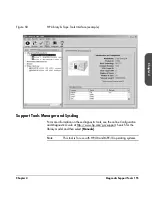
Page 133: ...V DRV 6 DRV DRV 3 DRV DRV 4 DRV DRV 1 DRV DRV 2 7 7 7 7 7 1 4 3 2 1 4 5 1 1 5 1 1 5 1 5 6 1 4 4 4 2 20 2 20 4 40 4 40 8 80 8 80 6 60 6 60 10 100 10 100 1 Vacant slot 5 Slave controller card 2 Remote management card 6 Library expansion card 3 Library controller card 7 Power supply standard or redundant 4 Fibre Channel interface optional ...

Page 134: ...apter 4 Table 19 Slave Controller LED Ready LED Color Description Yellow Default boot mode on power up Will remain in this state until board completes initialization Green Slave controller board is ready Slave Controller Card Ready 3 ...

Page 135: ...power on test or fatal error was detected during operation Green Card passed power on test Card ready 2 Link LED Color Description Green Indicates valid network connection 3 Activity LED Color Description Flashing Green Indicates transmission activity by the card s ethernet port Ready RS 232 10 100 Base T 2 ACT LNK Remote Management Card 1 2 3 ...

Page 136: ... needs firmware Yellow In the process of powering up Flashing Yellow Controller failed power on test Green Controller passed power on test 2 SCSI LED Color Description Green No bus connected or high voltage differential SCSI bus connected Yellow Error single ended SCSI device connected Ready Differential SCSI 3 HVDS Library Controller Card 1 2 ...

Page 137: ...rocess of powering up Flashing Yellow Controller failed power on test Green Controller passed power on test 2 SCSI LED Color Description Green No bus connected or low voltage differential SCSI bus connected Flashing Green Single ended SCSI bus attached SCSI performance reduced Yellow Error high voltage differential SCSI bus connected Controller Card Ready Differential SCSI 3 LVDS 1 2 ...

Page 138: ...D 8 80 and 10 100 Series Libraries Only Ready LED Color Description Yellow Powering up hardware error or card located on an unsupported level of the library Green Card is ready Flashing Green Indicates internal library communication bus activity Ready 2 Library Expansion Card ...

Page 139: ...re Channel is not connected 3 Ready LED Color Description Yellow Fibre Channel interface is being reset failed power on test or a fatal error was detected during operation Green Fibre Channel interface passed power on test Interface is ready Flashing Green One SCSI port is faulty 4 5 SCSI Bus LEDs Color Description Green SCSI bus is operational Yellow SCSI bus is not operational or is partially av...

Page 140: ...ow 2 Green Description Off On Drive is online and available Flashing Off Drive is offline and may be replaced without powering off the library On Flashing Drive is being brought online Flashing On Drive is offline Internal communication has been lost On On Drive module controller is in reset On Off Power on test in progress Flashing Off Drive module failed power on test Attention Drive Power 1 2 ...

Page 141: ...braries If you do not have this option your power supply will not have LEDs Table 26 Redundant Power Supply LEDs 1 DC Output LED Color Description Green DC output is within the specified limit Off DC output is outside of specified limit 2 AC Input LED Color Description Green AC input is within the specified limit Off AC input is outside of specified limit AC OK DC OK AC OK DC OK 1 2 1 2 ...

Page 142: ...bus or Fibre Channel bus is active can cause data loss or hang the host system Table 27 Troubleshooting Table Problem Solution Power Library will not power on Check all power cord connections Make sure the power standby switch is on Make sure there is power to the outlet by trying another working outlet Verify that the LEDs on the back of the library are on and that the fans are turning to ensure ...

Page 143: ...display messages appear Make sure the power cord is connected Make sure the power switch is on Check that the LEDs on the back of the library are on and the fans are turning Interpreting Library LEDs on page 130 Power cycle the library Try to access the library from the web or through a host based diagnostic tool Using the Remote Management Card on page 96 Download library firmware Upgrading Firmw...

Page 144: ...ive Tape stuck in storage slot Using the front panel display open the appropriate drawer Slide the drawer outward and remove the magazine Pull the tape out Reinsert the magazine If the magazine is damaged contact your service representative Transport is misaligned Transport won t get a tape Tape drive transport is misaligned Run the Recalibrate Library test See Running Library Diagnostic Tests on ...

Page 145: ... LTO CM has failed and the drive has found no data to recover Replace the data cartridge A cartridge that has data written to it and is write enabled is rejected by the drive LTO CM has failed or is damaged The data can still be recovered Contact your support representative for more information After data recovery replace the cartridge A cartridge that has data written to it and is write protected...

Page 146: ...ng cartridge with a new one If the message reappears when a particular data cartridge is used verify that the data cartridge is readable by Clearing the error message Reading the tape again If the data cartridge can be read backup data from the damaged cartridge to another cartridge and discard the damaged one Cannot load the cleaning cartridge Ensure you are using an approved cleaning cartridge f...

Page 147: ...eaning cartridge specifically designated for each drive type Cause Wrong tape format Attempting to load read or write tapes that were written in other formats can cause cleaning lights Cause Abnormal build up of head debris Frequent load unload operations with minimal tape reading or writing can cause this condition Do not perform frequent load unloads without also doing tape operations The front ...

Page 148: ... of cleaning cartridges Use of a cleaning cartridge should only be done when the drive front panel states cleaning required Cause Old firmware revisions If a cleaning tape does not resolve a cleaning light issue make sure the latest drive firmware is being used Connections Changed drive SCSI ID but the new ID is not recognized by the host computer Check that all SCSI devices on the same bus have d...

Page 149: ...is properly installed and configured using HP Library Tape Tools available from http www hp com support TapeTools Power cycle the library and power down the host Wait until the library completes its power cycle before powering up the host Check for SCSI ID conflicts Setting SCSI IDs on page 106 If using Fibre Channel make sure you power on the devices in the correct order switch hub library host C...

Page 150: ...cess by listing the domains to exclude in the Connections Advanced page of the browser options Check your browser s caching options to ensure the browser is looking for newer versions of the stored pages Configuring the Remote Management Card on page 99 Library Performance HP UX host responds slowly or crashes after connecting to the library Check the SCSI IDs of all devices on the host buses to e...

Page 151: ...oblems due to bad spots on the tape requiring retries Ensure that the backup software is using fixed length records or blocks to maximize throughput and has not defaulted to a smaller record size 64K should be sufficient Ensure that the data is being compressed however do not turn on both software and hardware compression Check the size of the files Backing up several small files can impact perfor...

Page 152: ...ge drives Front Panel Display Front panel display does not work Power cycle the library Attempt to access the library through the remote management card See Using the Remote Management Card on page 96 Attempt to access the library from the host computer either SCSI or Fibre Channel depending on how the library is configured Contact your service representative The soft keys on the front panel displ...

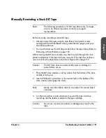
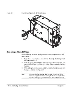
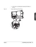
Page 153: ...ve module view the drive hub through the clear plastic to determine if the tape has been rewound If the tape has not been rewound follow the steps below and refer to Figure 48 on page 152 Caution The DLT drive does not automatically eject a cartridge if a power failure occurs 1 Place the DLT drive module on its top side so that the bottom of the drive module is facing up 2 Insert a Phillips 2 scre...

Page 154: ...uck DLT Tape on page 151 2 Locate the spring loaded latch near the opening on the drive module and push it outward item 1 in Figure 49 Ensure that you move both parts of the latch 3 While holding the latch outward rotate the thumb wheel drive gear until the tape ejects item 2 in Figure 49 Note If turning the thumb wheel does not eject the tape or if you encounter high resistance in turning the thu...

Page 155: ...Chapter 4 Troubleshooting Common Problems 153 Chapter 4 4 Verify the tape is not damaged see Inspecting DLT Cartridges on page 74 Figure 49 Spring Loaded Latch and Thumb Wheel 2 1 ...

Page 156: ... configuration identification inventory and drive information for the library Easily update library and drive firmware Upgrading Firmware on page 176 Run advanced diagnostic tests including connectivity read write media validation and testing library functionality View library and drive error logs Generate a detailed support file that can be emailed or faxed to your support representative for anal...

Page 157: ...ce example Support Tools Manager and Sysdiag For more information on these diagnostic tools see the online Configuration and Diagnostic Guide at http www hp com go support Search for the library model and then select Manuals Note This tool is for use with HP UX and MPE iX operating systems ...

Page 158: ...lect Stop to abort a test The current test cycle completes before the test stops Stopping the test may take a few minutes Main Menu Administration Run Test Table 28 Front Panel Diagnostic Tests Test Description Check Inventory Physically scans the entire library to determine which slots and drives contain tapes and reads all bar code labels Recalibrate Library Performs the power up self tests Each...

Page 159: ...d Note The transport assembly automatically unlocks when library is powered on Unlock Transport Unlocks the transport assembly without power cycling the library The transport must have already been locked to use this test Note The transport assembly automatically unlocks when library is powered on Test Transport Comm Exercises the infrared communications path between the library controller and the...

Page 160: ...ming this test to ensure that tapes are returned to their original locations Selects a random full storage slot moves the tape to the drive and repeats the process until all drives are full The test locates a full slot a full drive an empty slot and then performs an exchange Table 28 Front Panel Diagnostic Tests Test Description ...

Page 161: ...n on the following Removing and Replacing Cards on page 160 Removing and Replacing Drive Modules on page 162 Replacing the Redundant Power Supply on page 169 Removing the Library Cover and Feet 2 20 4 40 Series Only on page 172 Removing and Replacing a Cosmetic Door on page 174 Upgrading Firmware on page 176 5 ...

Page 162: ...er a U S Department of Health and Human Services DHHS Radiation Performance standard according to the Radiation Control for Health and Safety Act of 1968 and EN60825 1 A11 safety of laser products The compliance statement is located on the module Before powering the library off to remove a card review the LEDs on the back of each card to ensure there is no activity see Interpreting Library LEDs on...

Page 163: ... the card is flush with the library This will help ensure that the backplane pins are optimally aligned 3 Tighten the thumbscrews with a flat blade screwdriver 4 Reconnect external cables 5 Power on the library 6 Download new firmware see Upgrading Firmware on page 176 7 If installing Fibre Channel cards for the first time configure the library from the front panel See Configuring the Library for ...

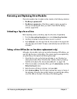
Page 164: ...s automatically rewound before it is unloaded Taking a Drive Offline for on line drive replacement only Although a drive module can be removed without powering off the library you must first take the drive module offline This process may be accomplished by using the library s front panel and following these steps 1 Check the drive icons on the front panel display to see if the drive has already be...

Page 165: ...r plate 2 Loosen the thumbscrews on each side of the connector plate located in the middle of the drive module Figure 51 on page 163 If this is your first time loosening the thumbscrews use a screwdriver 3 Gently remove the connector plate with SCSI cable s still connected Caution Use standard precautions for electro static discharge ESD protection 4 Grasp the ribbon cable that is plugged into the...

Page 166: ...e 52 on page 164 7 Using the handle that is mounted on the back of the drive module pull the drive module straight out with one hand while supporting the bottom of the drive module with the other hand Caution As the drive module is pulled out support the bottom of the drive module to avoid dropping or damaging it WARNING To avoid injury do not insert your hand or foreign objects through the empty ...

Page 167: ... the empty drive bay and into the vertical lift assembly area 1 Hold the drive module with one hand on the drive module handle while the other hand supports the bottom Figure 53 on page 165 2 Install the drive by inserting the rail at the top of the drive module into the slot at the top of the drive module opening Note Higher force will be required in the last half inch of insertion to engage the ...

Page 168: ...e drive has been brought online When the drive is successfully brought online the new drive will adopt the SCSI ID of the current drive position Note If you have increased the number of drives since the last power cycle you must power cycle the library for the library to recognize the additional drives Note You may get a drive firmware mismatch error if you have multiple drives with different firm...

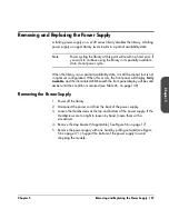
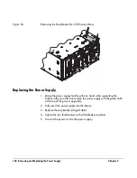
Page 169: ...is not in optimum configuration When this occurs the front panel will display Partly Available and the illuminated LED beneath the front panel display will be solid amber until the condition is resolved see Table 26 on page 139 Removing the Power Supply 1 Power off the library 2 Disconnect the power cord from the back of the power supply 3 Loosen the thumbscrews at the top and bottom of the power ...

Page 170: ...ower supply handle with one hand while supporting the bottom with your other hand Align the power supply with the guide notch at the top of the power supply bay 2 Fully insert the power supply into the library 3 Replace the stop bracket if applicable 4 Tighten the two thumbscrews with a flat blade screwdriver 5 Connect the power cord to the power supply ...

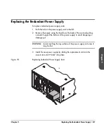
Page 171: ...Remove the supply using the handle on the back of the unit and pulling outward Support the bottom of the power supply to avoid dropping or damaging it WARNING Avoid touching the top surface of the power supply unit since it may be hot 3 Install the new power supply by sliding the replacement unit into the vacant slot until it clicks into place Figure 55 Replacing Individual Power Supply Units ...

Page 172: ...here is no activity on the SCSI bus 2 Remove the power supply module by loosening the two 6 32 x 25 T 15 screws and pulling the module straight out 3 Install the replacement power supply module by aligning the bottom of the module with the bottom of the power supply bay 4 Fully insert the power supply module into the back of the library 5 Tighten the two screws 6 The replacement supply comes with ...

Page 173: ... the bottom of the module By default power is always kept on to ensure redundant backup Note The redundant power supply module FRU comes with the entire module and one power supply unit If you need an individual unit and not the entire module then use the one that comes with the replacement module and discard the rest of the housing Power Supply Module Power Supply Unit ...

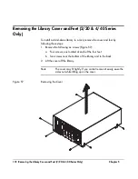
Page 174: ...move the cover and feet by following these steps 1 Remove the following six screws Figure 57 a Four screws one located at each of the four feet b Two screws near the bottom of the library and in the back 2 Lift the cover off the library Note The cover may fit tightly If you cannot remove it easily ease the sides out while lifting up on the cover Figure 57 Removing the Cover ...

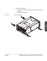
Page 175: ...ibrary Cover and Feet 2 20 4 40 Series Only 173 Chapter 5 3 Remove the feet as follows a Remove the 10 24 torx T20 machine screws from the side of each foot assembly b Slide the feet off the library Figure 58 Removing the Feet ...

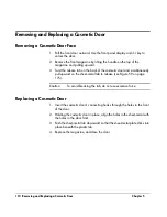
Page 176: ... of the cosmetic door and simultaneously pull upward on the sheet metal tab to release see Figure 59 on page 175 Caution To avoid breaking the tab do not use excessive force Replacing a Cosmetic Door 1 Insert the cosmetic door s connecting hooks through the holes in the front of the door 2 Holding the cosmetic door in place align the holes in the sheet metal with the holes in the door front 3 Push...

Page 177: ...Chapter 5 Removing and Replacing a Cosmetic Door 175 Chapter 5 Figure 59 Removing the Front Door Face 1 2 3 1 Release tab 2 Sheet metal tab 3 Cosmetic door connecting hooks ...

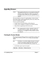
Page 178: ... firmware Using the remote management card library and LTO drive firmware Using a firmware upgrade tape drive firmware only Note After upgrading firmware library configuration settings will revert back to the factory defaults which could affect remote management For a complete list of factory defaults see Table 12 on page 91 Checking the Firmware Revision Before downloading new firmware check your...

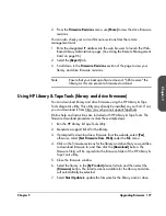
Page 179: ...tility may already be installed on your host If not you can download it from http www hp com support TapeTools Online help and instructions are included with HP Library Tape Tools The firmware download procedure involves these simple steps 1 Run the HP Library Tape Tools utility 2 Generate a support ticket for the library 3 If prompted to download new firmware from the website select Yes otherwise...

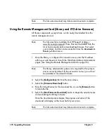
Page 180: ... IP address within your web browser to launch the Web Based Library Administrator pages See Using the Remote Management Card on page 96 Note The library administrator password is required for this process and is not set by default If the password is not set you will not be permitted to download firmware 2 Select the Configuration tab from the main screen 3 Select the Firmware Download button 4 Ent...

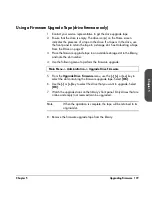
Page 181: ...ade tape in an available storage slot in the library and note the slot number 4 Use the following menu to perform the firmware upgrade 5 From the Upgrade Drive Firmware menu use the or key to select the slot containing the firmware upgrade tape Select OK 6 Use the or key to select the drive that you want to upgrade Select OK 7 Watch the upgrade status on the library s front panel Only drives that ...

Page 182: ...180 Upgrading Firmware Chapter 5 ...

Page 183: ...e following Environmental Specifications on page 182 Library Specifications on page 183 Physical Specifications on page 184 Cable Specifications on page 186 Drive Compatibility Specifications on page 187 HP Ultrium Drive and Media Specifications on page 189 DLT Drive and Media Specifications on page 192 A ...

Page 184: ...ure media 25º C maximum Non operating wet bulb temperature drive 46º C maximum Gradient 10º C per hour Transportation 30 to 60º C 14 consecutive days Humidity Operating 20 to 80 RH non condensing Non operating 10 to 90 RH non condensing Shock Operating 4 0g half sine Non operating 10g 24ips Vibration 5 500 Hz Operating 0 21g RMS random Non operating 2 1g RMS random Operating 0 25g 0 peak swept sin...

Page 185: ...e tape exchange time mean time to eject tape from drive robotically exchange tape from magazine and reload drive 46 seconds Storage capacity Dependent upon the model and configuration MTBF 100 000 Hours robotics only 50 000 Hours including drives 45 000 library only MSBF robotics 1 000 000 swaps robotics Line voltage 100 127 200 240 VAC Auto selecting Line frequency 50 60 HZ ...

Page 186: ...8 80 10 100 Series 1 969 mm 78 in Width 2 20 4 40 6 60 Series 442 mm 17 in 8 80 10 100 Series 597 mm 24 in Depth 2 20 4 40 6 60 Series 696 mm 27 in 8 80 10 100 Series 940 mm 37 in Weight net 2 20 Series 40 kg 87 lb 4 40 Series 75 kg 165 lb 6 60 Series 104 kg 249 lb 8 80 10 100 Series approximately 227 kg 500 lb Weight packaged 2 20 Series 41 kg 90 lb 4 40 Series 82 kg 180 lb 6 60 Series 111 kg 244...

Page 187: ...tocols Available as HVD or LVD SE Fibre Channel Interface One 1 0625 Gbps port Embedded shortwave optical connector type SC Supports FC AL arbitrated loop and FC SW switched fabric topologies FCP 2 compliant Private Loop Direct Attach PLDA profile Class 3 connection with SCSI FCP protocol Tachyon TL protocol controller RMC interface RJ45 standard network connector 10 100 Base TX network port Table...

Page 188: ...B second Wide 3 meters 12 meters 25 meters Normal Slow SCSI 5MB second Narrow 10MB second Wide 6 meters 12 meters 25 meters Ultra SCSI 3 20 MB s single ended 40 MB s LVD HVD 3 meters for 4 devices 1 5 meters for 8 devices 12 meters 25 meters Ultra2 SCSI 40 MB s HVD 80 MB s LVD N A 12 meters 25 meters Ultra3 SCSI 160 MB s LVD N A 12 meters N A Table 33 Fibre Channel Cable Specifications Cable Maxim...

Page 189: ...ata cartridges are unique for each drive technology Damage may occur if inappropriate media is used in the tape drives Table 35 on page 187 shows drive technologies and compatible unformatted data cartridges Table 34 Drive Read Write Compatibility Drive Type Read compatible Write compatible DLT 8000 DLT 4000 DLT 7000 DLT 8000 DLT 4000 DLT 7000 DLT 8000 LTO Ultrium LTO Ultrium LTO Ultrium Table 35 ...

Page 190: ... compatible cleaning cartridges Note Ensure you use the correct cleaning cartridge for your tape drive Table 36 Cleaning Cartridge Compatibility Drive type Cleaning cartridge type HP part number Quantum DLT DLTtape cleaning cartridge C5142A HP Ultrium HP Ultrium Universal Cleaning Cartridge C7978A ...

Page 191: ...trium Read write transfer rate maximum sustained Non compressed mode 15 MB second Compressed 2 1 typical 30 MB second Burst transfer rate 80 MB second Average access time 90 seconds Loading time 25 seconds maximum Unloading time 13 seconds maximum MTBF 250 000 hours Interface type Low Voltage Differential LVD Ultra 2 SCSI High Voltage Differential HVD Ultra SCSI ...

Page 192: ... media has passed Ultrium format compliance testing For best results always use HP branded media Figure 60 Ultrium Format Trademark Table 38 Ultrium Media Specifications Characteristic Ultrium Media Formatted capacity 200 GB 2 1 typical compression Basic description 0 5 inch metal particle Tape length 580 meters 1903 feet Cartridge dimensions 10 2 x 10 5 x 2 2 cm 4 02 x 4 15 x 0 85 in Shelf life 3...

Page 193: ...ge H represents Hewlett Packard as the drive manufacturer n is the volume serial number and XY represents the media ID as stated above Bar codes will resemble CLNHnnL1 Table 39 Ultrium Cartridge Bar Code Specifications Description Specification Data cartridge message 8 character 6 alphanumeric user preference followed by 2 alphanumeric media ID Cleaning cartridge message 8 character CLN H 2 numeri...

Page 194: ... rate maximum sustained DLT Type IV media Non compressed mode 6 0 MB second Compressed 2 1 typical 12 0 MB second Burst transfer rate 20 MB second Average access time 60 seconds Loading time to BOT for previously written tape 37 seconds average MTBF 250 000 hours Interface type Low Voltage Differential LVD Fast wide SCSI High Voltage Differential HVD Fast wide SCSI ...

Page 195: ...ic DLT Type IV Media DLT 8000 Formatted capacity 40 GB non compressed 80 GB 2 1 typical compression Basic description 0 5 inch metal particle Tape length 557 meters 1828 feet Cartridge dimensions 10 4 x 10 4 x 2 5 cm 4 1 x 4 1 x 1 0 in Shelf life 30 years minimum 20 C 40 RH non condensing Cartridge life 1 000 000 passes any point on the tape passing the recording head in either direction 2 000 loa...

Page 196: ...ecification Data cartridge message 6 character 2 alpha 4 numeric AAnnnn Cleaning cartridge message 6 character CLN 3 numeric CLNnnn Dimensions 5 6 cm x 2 1 cm 2 2 in x 82 in Symbology code 39 without check digit Start stop characters Narrow bar 0 036 cm 0 014 in Ratio 2 5 1 Print quality ANSI Grade A ...

Page 197: ...tomer Support Appendix Overview This appendix provides information on the following Registering Your Product on page 196 Support Services on page 197 Contacting HP Customer Support on page 202 Warranty Information on page 207 B ...

Page 198: ...mer Support HP registration web site http www register hp com HP customers who register on our web site join a select group who register to receive Technical support updates Special Hewlett Packard offers Direct to you details on Ideas and ways to use your new HP Surestore Tape Library Other exciting HP products News on emerging technologies ...

Page 199: ...uptime needs SupportPacks SupportPacks are available within180 days of your purchase If you choose to purchase one your warranty will be upgraded Once your warranty has expired post warranty SupportPacks are also available Table 43 on page 198 lists HP SupportPack service options Note To order HP SupportPacks visit http www hp com hps support supportpack or contact your support or sales representa...

Page 200: ...same day onsite H4435A E 3 year 24x7 onsite U2064PA PE post warranty 1 year next day onsite H2735PA PE post warranty 1 year same day onsite 6 60 series H5534A E 3 year same day onsite H4436A E 3 year 24x7 onsite U2065PA PE post warranty 1 year next day onsite H2736PA PE post warranty 1 year same day onsite 80 and 100 series U2061A E 3 year same day onsite U2062A E 3 year 24x7 onsite U2066PA PE pos...

Page 201: ...able 45 on page 200 lists post warranty service contracts and upgrade options Note To purchase a service contract or for more information contact your support or sales representative Table 44 Post Warranty Service Contracts Option Description 01A Standalone hardware call to repair 6 hour response 24x7 coverage 02A Onsite same day 4 hour response 02C Onsite next working day response 02G Onsite 4 ho...

Page 202: ...tion Description 01B Standalone upgrade to hardware warranty to 6 hour call to repair 24x7 coverage 07A Priority 07G Upgrades hardware warranty response to 24x7 07V Upgrades hardware warranty to 6 hour call to repair 07X Upgrades hardware warranty to 4 hour call to restoration ...

Page 203: ...rmation Your name and telephone number Product name release number operating system build and serial number Detailed list of error messages reported Configuration files and log files related to the problem Screen dumps if applicable Explanation of how to reproduce the problem if possible Events that may have contributed to the problem recent operator actions recent events in the software or the sy...

Page 204: ...office to prepare for the proper response level needed If your library fails while under the support contract period contact the appropriate support number included in your contract information If your library fails after the warranty period contact your authorized HP dealer distributor or the nearest HP sales and service office Customers in the US and Europe can use a credit card for phone assist...

Page 205: ... North and South America Note For the latest list of phone numbers for HP Customer Support see http www hp com go support Phone charges may apply Argentina 541 778 8380 Brazil 011 829 6612 Canada 905 206 4663 Chile 800 360 999 Mexico 800 427 6684 United States 970 635 1500 Monday Friday 7 am 5pm Mountain Time Venezuela 800 47 888 Caracas 207 8488 ...

Page 206: ...port Phone charges may apply Austria 43 0 7114 201080 Belgium Dutch 32 0 2 626 8806 Belgium French 32 0 2 626 8807 Denmark 45 39 29 4099 English International 44 0 171 512 52 02 Finland 358 0 203 47 288 France 33 0 1 43 62 34 34 Germany 49 0 180 52 58 143 Ireland 353 0 1 662 5525 Israel 972 0 9 9524848 Italy 39 02 264 10350 Netherlands 31 0 20 606 8751 Norway 47 22 11 6299 Portugal 351 0 1 318 00 ...

Page 207: ... 512 52 02 Asia Pacific Customer Support Centers Note For the latest list of phone numbers for HP Customer Support see http www hp com go support Phone charges may apply Australia 61 3 8877 8000 China 86 0 10 6564 5959 Hong Kong 800 96 7729 India 91 11 682 6035 Indonesia 62 21 350 3408 Japan 81 3 3335 8333 Korea 82 2 3270 0700 Outside Seoul 080 999 0700 Malaysia 60 3 295 2566 ...

Page 208: ...nd 64 9 356 6640 Penang 1 300 88 00 28 Philippines 63 2 867 3551 Singapore 65 272 5300 Taiwan 886 2 717 0055 Thailand 66 2 661 4000 Vietnam 84 0 8 823 4530 Elsewhere Contact your authorized HP dealer distributor or the nearest HP sales and service office ...

Page 209: ... return of the product 4 HP products may contain remanufactured parts equivalent to new in performance or may have been subject to incidental use 5 The warranty period begins on the date of delivery or on the date of installation if installed by HP If customer schedules or delays HP installation more than 30 days after delivery warranty begins on the 31st day from delivery 6 Warranty does not appl...

Page 210: ...WARRANTY STATEMENT ARE THE CUSTOMER S SOLE AND EXCLUSIVE REMEDIES EXCEPT AS INDICATED ABOVE IN NO EVENT WILL HP OR ITS SUPPLIERS BE LIABLE FOR LOSS OF DATA OR FOR DIRECT SPECIAL INCIDENTAL CONSEQUENTIAL INCLUDING LOST PROFIT OR DATA OR OTHER DAMAGE WHETHER BASED IN CONTRACT TORT OR OTHERWISE ...

Page 211: ...For more information see Information Needed for Support on page 202 Each hard error code and qualifier code is paired with a list of recovery suggestions The library suggests the appropriate recovery procedures which could include Power cycling the library Removing a tape from the drive Checking the library or host configuration Checking the cable connections data or power Running diagnostic tests...

Page 212: ...ry controller card See Interpreting Library LEDs on page 130 to understand what the LEDs may indicate If failure persists the library controller card may be faulty 9 09H Failed translate motor test Cannot translate the transport Check for a possible obstruction in the transport pathway and remove it The umbilical cable may be faulty If the transport moves a little but cannot fully rotate around th...

Page 213: ...been fully inserted into slots 14 0EH Transport failed to find the plunge home position The plunge motor can be moved Therefore the motor and umbilical cable are probably not indicated Replace the transport assembly 15 0FH Has wrong library family firmware or the controller is on the wrong level Download new firmware see Upgrading Firmware on page 176 18 12H Failed because magazine door is open Cl...

Page 214: ...assis interconnect cable connection is secure 26 1AH Upper level fan cable failed See Troubleshooting Common Problems on page 140 for troubleshooting procedures 27 1BH Transport controller unable to communicate with transport Replace the transport assembly 28 1CH Transport controller needs new firmware Update the library s firmware see Upgrading Firmware on page 176 29 1DH Failed transport firmwar...

Page 215: ...urrent locations The library needs at least one tape and an empty slot to perform this test For a drive test it cannot rewind the media 57 39H Test not run not enough tapes in the library Load one additional tape into the library 58 3AH Test not started the transport contains a tape Run the Empty Transport test see Running Library Diagnostic Tests on page 156 59 3BH Failed to put tape into magazin...

Page 216: ...ate testing 67 43H Transport stuck at vertical home position Note the error code qualifier to help determine appropriate testing 68 44H Failed to move after finding the plunge home position Note the error code qualifier to help determine appropriate testing 69 45H Transport unable to move to the end of the track Note the error code qualifier to help determine appropriate testing 70 46H Failed inve...

Page 217: ...r code qualifier to help determine appropriate testing 76 4CH Failed to perform an inventory check Note the error code qualifier to help determine appropriate testing 77 4DH Transport moved above highest detected level Run the Test Vertical Motion test see Running Library Diagnostic Tests on page 156 78 4EH Not all drives in the library are the same type Check to ensure that you have the correct t...

Page 218: ...ve module unable to communicate with drive Power cycle the library 102 66H Drive command timeout on drive module controller Command timeout on 8051 103 67H A drive module controller has failed Power cycle the library and re try Replace the drive module if unsuccessful see Removing and Replacing Drive Modules on page 162 104 68H Failed drive module initialization Power cycle the library 105 69H Dri...

Page 219: ...unable to communicate with Fibre Channel card Ensure Fibre Channel card is installed and fully seated 121 79H Failed to detect all of the Fibre Channel cards Power cycle the library 122 7AH Fibre Channel board command timeout Power cycle the library 123 7BH A Fibre Channel card has failed Power cycle library and retry Replace card if unsuccessful Removing and Replacing Cards on page 160 126 7EH Mo...

Page 220: ...e one card installed on the library and on the bottom library level See Figure 47 on page 131 136 88H Failed because the library expansion card is missing or faulty Ensure the library expansion card is properly installed seated and connected 137 89H Failed because the library expansion card is present but on the wrong library level Move the library expansion card to the fifth library level See Fig...

Page 221: ... help determine appropriate testing 159 9FH Transport barcode reader cable is missing or faulty Note the error code qualifier to help determine appropriate testing 160 A0H Transport illuminator cable is missing or faulty Note the error code qualifier to help determine appropriate testing 161 A1H Two transport cables are missing or faulty Note the error code qualifier to help determine appropriate ...

Page 222: ...220 Library Error Codes Appendix ...

Page 223: ...s transported C calibration A routine that is run immediately after a tape cartridge is loaded in order to determine if the tape is blank or written compatible with the drive and capable of being written and read cleaning tape A tape that is used only for cleaning a drive D DLT Digital Linear Tape a family of tape device and media technologies developed by Quantum Corporation drawer The area of th...

Page 224: ...ge devices and other peripherals Fibre Channel is capable of transmitting at rates exceeding one gigabit per second in both directions simultaneously Fibre Channel Arbitrated Loop FC AL Topology that provides a low cost solution for attaching multiple Fibre Channel ports in a loop without switches front panel display An LCD liquid crystal display equipped with five soft keys mounted on the front o...

Page 225: ...o connect the library controller card to a drive May also be referred to as daisy chain cables L latch stop A spring loaded safety device that protrudes through the mounting rail The latch stop allows 2 20 4 40 and 6 60 tape libraries to be pulled approximately two thirds out of a rack while preventing them from being pulled out completely LEDs Light emitting diodes also called lamps found in vari...

Page 226: ...pe into a drive or unloading a tape from a drive N node An addressable entity connected to an I O bus or network used to refer to storage devices and subsystems nesting The menu approach implemented in the library that uses increasing levels of library control O odometer A front panel option that displays the odometer logs for power on hours and moves originator A Fibre Channel term that refers to...

Page 227: ... keys Five buttons located along the bottom edge of the front panel display that are used to execute commands on the display swap Two related library actions or moves such as moving a tape from a slot to a drive and then back to a slot switch A device that provides a n by n interconnect to allow a port to have full communication bandwidth with any other port while other communications are occurrin...

Page 228: ... W web based library administrator Describes the interface that allows you to monitor and manage the library over the network via the remote management card wide SCSI A 68 pin connector that can be single ended or differential in implementation ...

Page 229: ...g 213 write protecting tapes 70 bar code DLT labels 79 80 Ultrium labels 72 73 bar code labels 12 BOOTP 97 100 bulk erasing 69 bulk load 221 bus 221 C cables fibre channel 12 13 43 56 186 fibre channel 2 20 45 fibre channel 4 40 46 fibre channel 6 60 47 fibre channel 8 80 and 10 100 49 SCSI 12 13 31 34 40 56 122 186 SCSI 2 20 36 SCSI 4 40 37 SCSI 6 60 38 SCSI 8 80 and 10 100 39 40 choosing a locat...

Page 230: ...187 inspecting media 74 interface types 192 media cartridge life 193 removing a stuck tape 152 153 rewinding a stuck tape 151 152 drawer keys shipping location 30 drive and tape operations 86 88 drive cleaning 222 drive event log 112 drive firmware revision view ing 113 drive identity viewing 112 drive information categories available 112 viewing event log 112 drive information viewing identity 11...

Page 231: ...4 40 46 6 60 47 HVDS 223 I icons status bar 61 identifying errors 117 identity 223 drive viewing 112 library viewing 110 information menu 64 information gathered before contacting support 202 inspecting media DLT 74 Ultrium 69 installation check 50 154 installation fibre channel 41 47 installing a standalone library into a rack 17 30 installing clip nuts general tips 19 installing host bus adapter...

Page 232: ...mechanical 4 40 and 6 60 installation 24 lifting straps using for 2 20 23 loading a tape into a drive from front panel 86 location requirements 14 location of securing screws 30 location of library choosing 14 log drive event 112 low voltage differential SCSI in terface and terminators 34 LVDS 223 M MAC address 224 magazine 224 magazine access 224 magazines removal 82 mailslot 224 mailslot configu...

Page 233: ...g cards 160 161 removing cover standalone li brary 172 removing feet standalone li brary 173 removing magazines 82 removing replacing drive mod ules 162 171 retrieving library information 110 158 from front panel 110 running library diagnostic tests 156 S save element reserve viewing 112 screws securing 30 SCSI 225 cable connections 2 20 36 cable connections 4 40 37 cable connections 6 60 38 cable...

Page 234: ...0 83 write protecting DLT 77 write protecting Ultrium 70 tape drawer keys shipping lo cation 30 tape leader 74 tape magazine access 81 tape loading into a drive 86 tape loading into drive 86 tape unloading from drive 87 TCP IP 225 telephone support during war ranty 203 temperature and humidity spec ifications 182 templates for clip nuts 19 terminator 225 terminators 2 20 36 4 40 37 6 60 38 8 80 an...

Page 235: ... library configurations 112 W warranty 197 199 207 warranty telephone support during 203 web based library administrator 226 website Customer Care 202 weight library 17 25 54 58 weight reducing for installation 23 wide SCSI 226 world time zones 109 write protecting DLT media 77 Ultrium media 70 Z zones time 109 ...

Page 236: ...234 ...

Page 237: ......

Page 238: ...Copyright 2002 Hewlett Packard Company Printed in U S A Edition 5 June 2002 www hp com go support Printed on recycled paper C9521 90002 ...

Reviews: