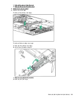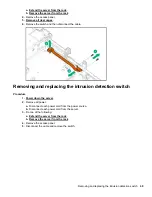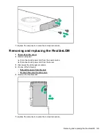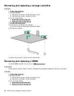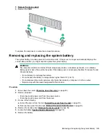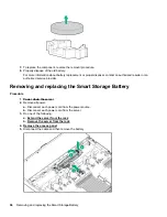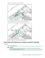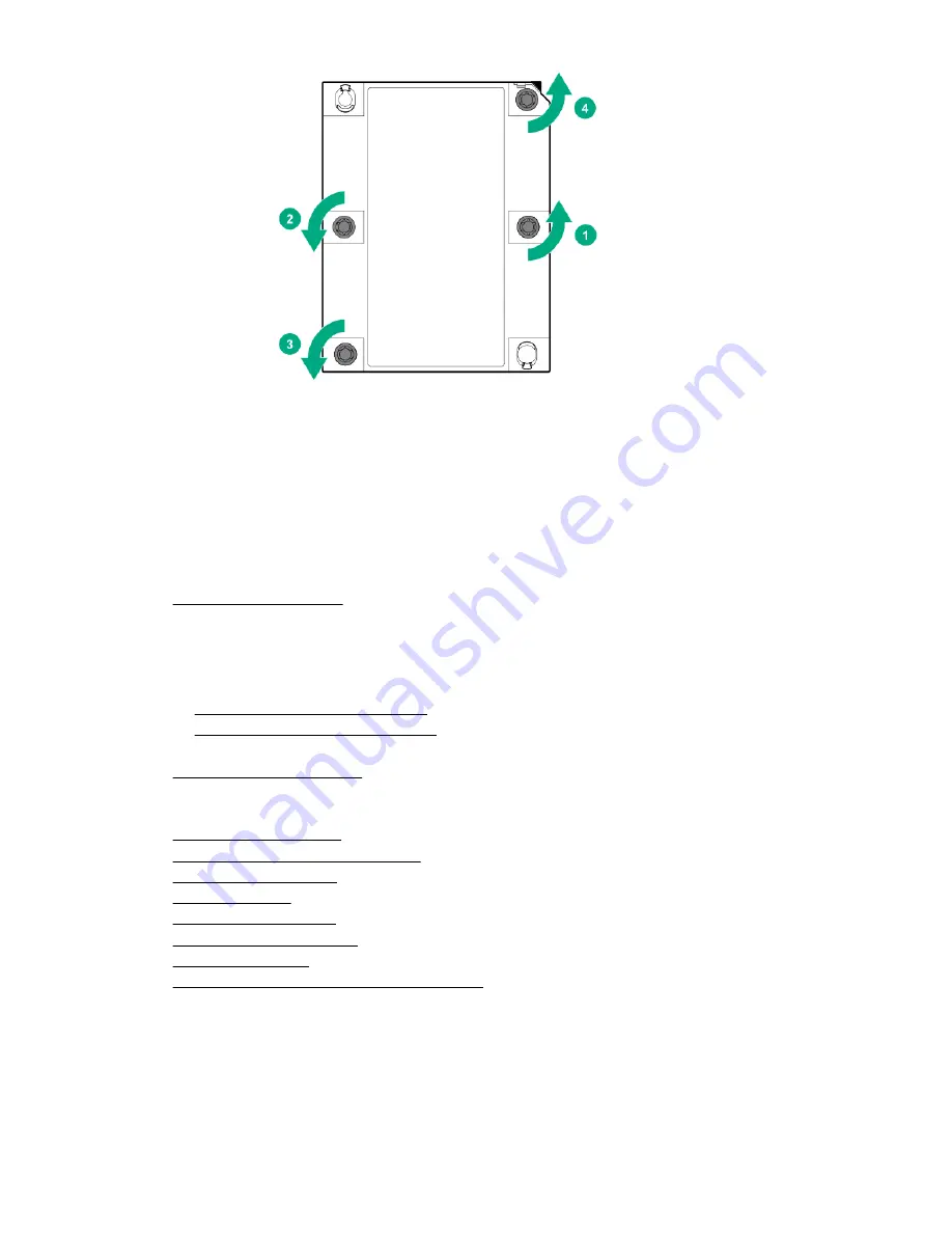
c.
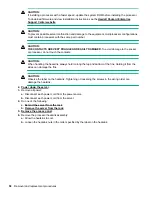
Lift the processor heatsink assembly and move it away from the system board.
d.
Turn the assembly over and place it on a work surface with the processor facing up.
e.
Install the dust cover.
To replace the component, reverse the removal procedure.
Removing and replacing the system board
Procedure
1.
2.
Remove all power:
a.
Disconnect each power cord from the power source.
b.
Disconnect each power cord from the server.
3.
Do one of the following:
a. Extend the server from the rack
b. Remove the server from the rack
4.
Remove all power supplies.
5.
.
6.
Take note of port numbers and cables connections to risers and the system board.
7.
Disconnect and remove all cables that are connected to risers or the system board.
8.
.
9.
Remove the GPU support bracket
11. Remove all fans
.
14. Remove all DIMMs
.
15. Remove the processor heatsink assembly
16.
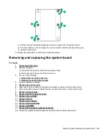
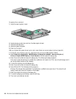
Loosen the system board thumbscrew, and then remove the system board.
Removing and replacing the system board
59
Summary of Contents for ProLiant DL360 Gen10
Page 27: ...Customer self repair 27 ...
Page 28: ...28 Customer self repair ...
Page 29: ...Customer self repair 29 ...
Page 30: ...30 Customer self repair ...
Page 35: ...Removing and replacing the bezel Removing and replacing the bezel 35 ...
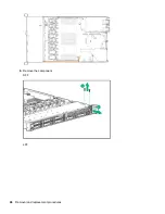
Page 66: ...6 Remove the component SFF LFF 66 Removal and replacement procedures ...

