HP ProBook 430 G7 Maintenance And Service Manual Download Page 72

8.

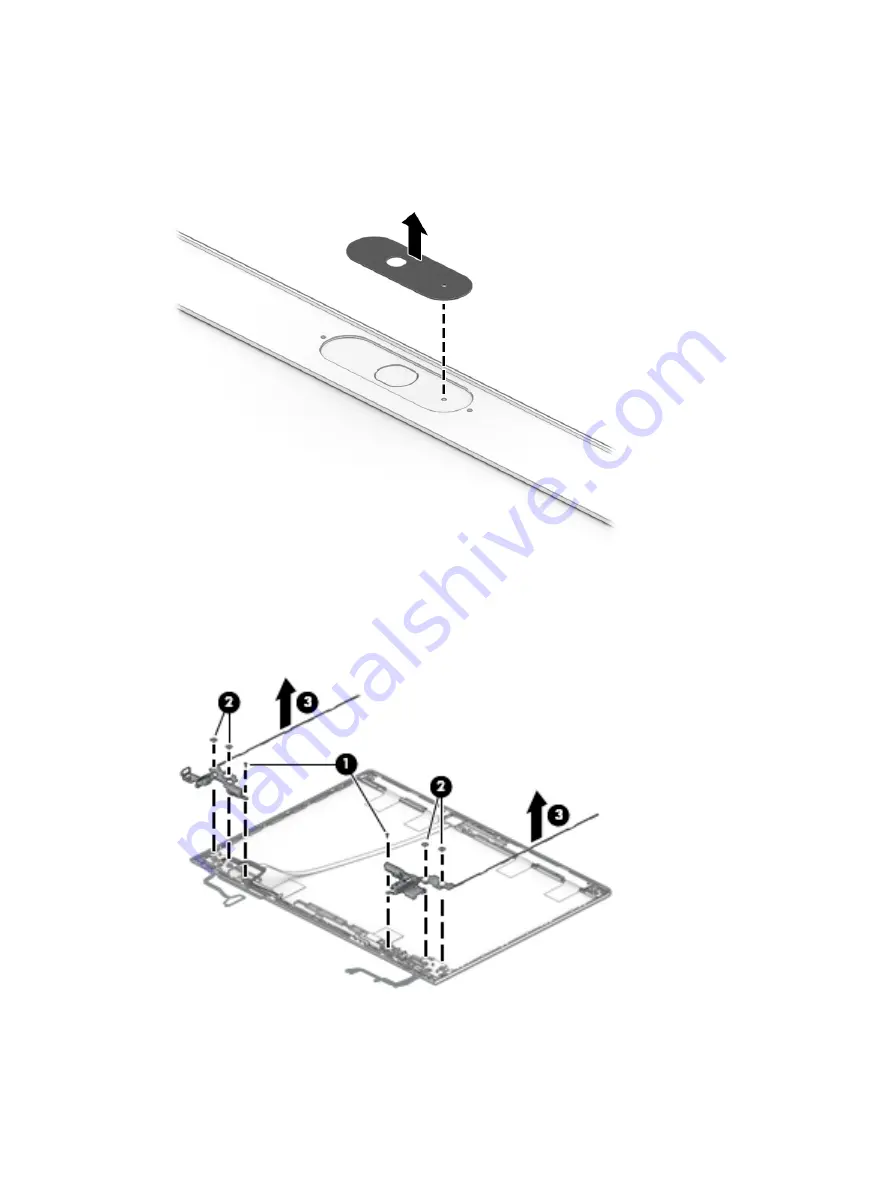
If it is necessary to remove the camera privacy cover, lift the cover straight up and off the top of the 
display.

The camera privacy cover is available as spare part number L77237-001.

9.

If it is necessary to remove the hinges from the display enclosure, remove the Phillips M2.0 × 4.0 screw 
(1) and the two Phillips broad head M2.5 × 2.5 screws (2) from the bottom of each hinge.

10.

Lift the hinges from the enclosure (3).

The display hinges are available as spare part number L77234-001.

64

Chapter 5   Removal and replacement procedures for Authorized Service Provider parts

Summary of Contents for ProBook 430 G7

Page 1: ...Maintenance and Service Guide HP ProBook 430 G7 Notebook PC IMPORTANT This document is intended for HP authorized service providers only ...

Page 2: ...tained herein First Edition November 2019 Document Part Number L76355 001 Product notice This guide describes features that are common to most models Some features may not be available on your computer Not all features are available in all editions or versions of Windows Systems may require upgraded and or separately purchased hardware drivers software or BIOS update to take full advantage of Wind...

Page 3: ...a hard flat surface Do not allow another hard surface such as an adjoining optional printer or a soft surface such as pillows or rugs or clothing to block airflow Also do not allow the AC adapter to contact the skin or a soft surface such as pillows or rugs or clothing during operation The computer and the AC adapter comply with the user accessible surface temperature limits defined by applicable ...

Page 4: ...iv Safety warning notice ...

Page 5: ...uch models 20 Display components touch models 22 Cable Kit 23 Bracket Kit 24 Mass storage devices 25 Miscellaneous parts 26 4 Removal and replacement procedures preliminary requirements 29 Tools required 29 Service considerations 29 Plastic parts 29 Cables and connectors 29 Drive handling 30 Workstation guidelines 30 Electrostatic discharge information 30 Generating static electricity 31 Preventin...

Page 6: ...board 50 Touchpad assembly 51 Fingerprint sensor assembly 52 Card reader board 54 RTC battery 56 System board 57 Display assembly touch models 61 Display assembly nontouch models 69 Power connector cable 80 Keyboard top cover 81 6 Computer Setup BIOS TPM and HP Sure Start 83 Using Computer Setup 83 Starting Computer Setup 83 Navigating and selecting in Computer Setup 83 Restoring factory settings ...

Page 7: ...ng Remote HP PC Hardware Diagnostics UEFI 90 Downloading the latest Remote HP PC Hardware Diagnostics UEFI version 90 Downloading Remote HP PC Hardware Diagnostics UEFI by product name or number 90 Customizing Remote HP PC Hardware Diagnostics UEFI settings 90 8 Backing up restoring and recovering 92 Backing up information and creating recovery media 92 Using Windows tools 92 Using the HP Cloud Re...

Page 8: ...11 Power cord set requirements 104 Requirements for all countries 104 Requirements for specific countries and regions 105 12 Recycling 107 Index 108 viii ...

Page 9: ...DisplayPort 2 Supports 3 independent displays when on the HP Thunderbolt Dock 120 W using USB C Max resolution 4K 30 Hz DisplayPort 1 or 4K 30 Hz DisplayPort 2 Panel 33 8 cm 13 3 inch HD 1366 768 LED backlight antiglare SVA 220 nits 45 CG eDP ultraslim No camera HD camera HD IR camera HD camera for WWAN 33 8 cm 13 3 inch FHD 1920 1080 LED backlight antiglare UWVA eDP No camera slim 45 CG 250 nits ...

Page 10: ...al Audio controls Integrated mono microphone non camera models only Integrated dual array microphone Integrated camera 720p HD select models only Integrated camera 720p HD IR select models only Camera privacy cover Supports WDR Wide Dynamic Range Headphone microphone combo jack RJ 45 network Realtek RTL8111HSH 10 100 1000 S3 S4 S5 wake on LAN with embedded NIC The following support S3 S4 S5 wake o...

Page 11: ...less Protection WLAN LAN WWAN switching Supports HP Connection Optimizer with Data Analytics Bluetooth S3 wake up support Support for Turbo Lite Wi Fi Compatible with Wi Fi CERTIFIED Miracast devices Supports WoWLAN S3 S4 AC Mode Wireless Wide Area Network WWAN select models only Integrated WWAN options by way of wireless module select models only SIM module Micro SIM 3FF WWAN cards are compatible...

Page 12: ...ium polymer soft pack HP Long Life HP Fast Charge Technology AC adapters 65 W Smart AC adapter right angle 4 5 mm 65 W Smart AC adapter right angle 4 5 mm Argentina 65 W Smart AC adapter right angle 4 5 mm EM 65 W straight USB Type C AC adapter 45 W Smart AC adapter right angle 4 5 mm 45 W Smart AC adapter right angle 4 5 mm Argentina 45 W Smart AC adapter right angle 2 prong 4 5 mm Japan only 45 ...

Page 13: ...Windows 10 Home 64 Plus Single Language Windows 10 Home 64 Plus Single Language Africa Market PPP Windows 10 Home 64 Plus Single Language APAC EM PPP Windows 10 Home 64 Plus Single Language India Market PPP Windows 10 Home 64 Plus Single Language Indonesia Market PPP Windows 10 Home 64 Single Language Windows 10 Home 64 Single Language Africa Market PPP Windows 10 Home 64 Single Language APAC EM P...

Page 14: ...cription Windows 10 Driver DVD Windows 10 Driver USB Windows 10 Professional 64 bit OS DVD Windows 10 Professional 64 bit OS USB Certified Microsoft WHQL Web only support Windows 10 Enterprise 64 Serviceability User replaceable parts AC adapter 6 Chapter 1 Product description ...

Page 15: ...es To access this guide Type HP Documentation in the taskbar search box and then select HP Documentation NOTE When a device is connected to the jack the computer speakers are disabled 2 USB SuperSpeed port Connects a USB device such as a cell phone camera activity tracker or smartwatch and provides high speed data transfer 3 HDMI port Connects an optional video or audio device such as a high defin...

Page 16: ...NOTE Cables and or adapters purchased separately may be required 6 Battery light When AC power is connected White The battery charge is greater than 90 Amber The battery charge is from 0 to 90 Off The battery is not charging When AC power is disconnected battery not charging Blinking amber The battery has reached a low battery level When the battery has reached a critical battery level the battery...

Page 17: ...l internal components NOTE The computer fan starts up automatically to cool internal components and prevent overheating It is normal for the internal fan to cycle on and off during routine operation 4 Memory card reader Reads optional memory cards that store manage share or access information To insert a card 1 Hold the card label side up with the connectors facing the computer 2 Insert the card i...

Page 18: ...our product 5 Camera privacy cover select products only By default the camera lens is uncovered but you can slide the camera privacy cover to block the camera s view To use the camera slide the camera privacy cover in the opposite direction to reveal the lens NOTE If you have both front facing and rear facing cameras when one camera lens is revealed and ready to use the other is concealed 6 Camera...

Page 19: ...ternal mouse click the Touchpad button or Press the Tab key repeatedly until the pointer rests on the Touchpad button Then press the spacebar to select the button Table 2 4 Touchpad components and their descriptions Component Description 1 Touchpad zone Reads your finger gestures to move the pointer or activate items on the screen 2 Left control zone Textured area that allows you to perform additi...

Page 20: ...amount of power 2 Caps lock light On Caps lock is on which switches the key input to all capital letters 3 Mute light On Computer sound is off Off Computer sound is on 4 Microphone mute light On Microphone is off Off Microphone is on 5 Num lk light On Num lock is on 6 Wireless light On An integrated wireless device such as a wireless local area network WLAN device and or a Bluetooth device is on N...

Page 21: ...own procedures are ineffective press and hold the power button for at least 5 seconds to turn off the computer To learn more about your power settings see your power options Right click the Power icon and then select Power Options 2 Speakers 2 Produce sound 3 Vent Enables airflow to cool internal components NOTE The computer fan starts up automatically to cool internal components and prevent overh...

Page 22: ... numeric keypad A numeric keypad superimposed over the keyboard alphabet keys When fn num lk is pressed the keypad can be used like an external numeric keypad Each key on the keypad performs the function indicated by the icon in the upper right corner of the key NOTE If the keypad function is active when the computer is turned off that function is reinstated when the computer is turned back on 6 n...

Page 23: ...omponent Description Vent Enables airflow to cool internal components NOTE The computer fan starts up automatically to cool internal components and prevent overheating It is normal for the internal fan to cycle on and off during routine operation Bottom 15 ...

Page 24: ...ickstand Service label Provides important information to identify your computer When contacting support you may be asked for the serial number the product number or the model number Locate this information before you contact support Table 2 9 Service label components Component 1 HP product name 2 Product ID 3 Serial number 4 Warranty period Regulatory label s Provide s regulatory information about...

Page 25: ...supported parts for your computer go to http partsurfer hp com select your country or region and then follow the on screen instructions NOTE Details about your computer including model serial number product key and length of warranty are on the service tag at the bottom of your computer See Labels on page 16 for details Computer major components 17 ...

Page 26: ...ard reader board cable is also available in the Cable Kit as spare part number L81305 001 L44537 001 8 RTC battery L02772 001 9 Power USB board NOTE The power USB board cable is available in the Cable Kit as spare part number L81305 001 L77227 001 10 Speaker assembly L44513 001 11 Fan L44514 001 12 Heat sink includes replacement thermal material L44512 001 13 System board includes integrated proce...

Page 27: ... L44796 002 Intel Wi Fi 6 AX201 802 11ax 2 2 Wi Fi Bluetooth 5 0 non vPro L57250 002 16 WWAN module Intel XMM 7360 LTE Advanced L15398 002 17 M 2 solid state drive 512 GB PCIe TLC L78043 001 512 GB PCIe L78044 001 512 GB PCIe 32 GB Optane memory L85513 001 256 GB PCIe L78042 001 256 GB PCIe 16 GB Optane memory L85341 001 128 GB SATA 3 TLC L78041 001 18 Hard drive 1 TB 5400 rpm 7 mm 832077 002 500 ...

Page 28: ...t number 1 Display bezel Models without a camera L77232 001 Models with an HD camera L77230 001 Models with an HD IR camera L77231 001 2 Display panel raw includes bezel adhesive and rear cover adhesive FHD models L78045 001 FHD privacy models L78047 001 HD models L78046 001 20 Chapter 3 Illustrated parts catalog ...

Page 29: ...era included in the Display Cable Kit includes bezel adhesive and rear cover adhesive L77235 001 7 WWAN antennas includes bezel adhesive and rear cover adhesive L78052 001 8 WLAN antennas includes bezel adhesive and rear cover adhesive L78051 001 9 Hinge Kit left and right includes bezel adhesive and rear cover adhesive L77233 001 10 Display rear cover includes wireless antennas and bezel adhesive...

Page 30: ... 001 Microphone board not illustrated L44541 001 3 Display camera cable assembly L77236 001 5 WWAN antennas L78054 001 6 WLAN antennas L78053 001 7 Hinge Kit includes left and right hinges L77234 001 8 Display rear cover includes wireless antennas For use in models with WLAN and without WWAN L78059 001 For use in models with WLAN and WWAN L78060 001 22 Chapter 3 Illustrated parts catalog ...

Page 31: ...lustrated L79383 001 Camera privacy cover not illustrated L77237 001 Cable Kit Table 3 4 Cable Kit components and their descriptions Item Description Spare part number Cable Kit includes the following parts L81305 001 1 Fingerprint sensor cable 2 Touchpad cable 3 Power USB board cable 4 Card reader board cable Cable Kit 23 ...

Page 32: ...components and their descriptions Item Description Spare part number Bracket Kit includes the following parts L81306 001 1 Fingerprint sensor bracket 2 USB Type C connector bracket 3 RJ 45 bracket 24 Chapter 3 Illustrated parts catalog ...

Page 33: ...12 GB PCIe L78044 001 512 GB PCIe 32 GB Optane memory L85513 001 256 GB PCIe L78042 001 256 GB PCIe 16 GB Optane memory L85341 001 128 GB SATA 3 TLC L78041 001 2 Hard drive 1 TB 5400 rpm 7 mm 832077 002 500 GB 7200 rpm 7 mm 703267 002 Hard Drive Hardware Kit includes the following parts L44510 001 3 Hard drive cover 4 Hard drive connector and cable Mass storage devices 25 ...

Page 34: ...tape fingerprint sensor conductive tape touchpad conductive tape and weight conductive tape L81307 001 Screw Kit L77238 001 Power cord 3 pin C5 black conventional 1 0 m 39 4 in for use in Argentina L19357 001 Australia L19358 001 Brazil L19359 001 Denmark L19360 001 Europe Austria Belgium Finland France Germany the Netherlands Norway and Sweden L19361 001 India L19363 001 Israel L19362 001 Italy L...

Page 35: ...United Kingdom and Singapore L19373 002 Power cord C7 black 1 0 m 39 4 in for use in Japan L19375 001 Power cord 3 pin C5NS black duckhead 1 0 m 39 4 in for use in Australia L36816 001 Denmark L36817 001 Europe Austria Belgium Finland France Germany the Netherlands Norway and Sweden L36818 001 Israel L36819 001 Japan L36821 001 North America L36822 001 The People s Republic of China L36823 001 Sou...

Page 36: ...ople s Republic of China L45270 001 South Africa L45271 001 Switzerland L45272 001 Thailand L45273 001 Taiwan L45274 001 United Kingdom L45275 001 Power cord 3 pin C5NS black duckhead 1 8 m 70 9 in for use in Brazil L48055 001 Denmark L50729 001 Duckhead connector only C5NS Australia L50818 004 North America L50818 002 The People s Republic of China L50818 005 South Korea L50818 001 The United Kin...

Page 37: ...stic parts IMPORTANT Using excessive force during disassembly and reassembly can damage plastic parts Cables and connectors IMPORTANT When servicing the computer be sure that cables are placed in their proper locations during the reassembly process Improper cable placement can damage the computer Cables must be handled with extreme care to avoid damage Apply only the tension required to unseat or ...

Page 38: ...ith approved static shielding material Use a wrist strap connected to a properly grounded work surface and use properly grounded tools and equipment Use conductive field service tools such as cutters screw drivers and vacuums When fixtures must directly contact dissipative surfaces use fixtures made only of static safe materials Keep the work area free of nonconductive materials such as ordinary p...

Page 39: ...000 V 2 000 V Removing DIPs from vinyl tray Removing DIPs from polystyrene foam Removing bubble pack from PCB printed circuit board Packing PCBs in foam lined box 2 000 V 3 500 V 7 000 V 5 000 V 4 000 V 5 000 V 20 000 V 11 000 V 11 500 V 14 500 V 26 500 V 21 000 V Multiple electric components can be packaged together in plastic tubes trays or polystyrene foam NOTE As little as 700 V can degrade a ...

Page 40: ...prevent static damage at the work area use the following precautions Cover the work surface with approved static dissipative material Provide a wrist strap connected to the work surface and properly grounded tools and equipment Use static dissipative mats foot straps or air ionizers to give added protection Handle electrostatic sensitive components parts and assemblies by the case or PCB laminate ...

Page 41: ...D sensitive parts and assemblies with conductive or approved containers or packaging Keep ESD sensitive parts in their containers until the parts arrive at static free workstations Place items on a grounded surface before removing items from their containers Always be properly grounded when touching a component or assembly Store reusable ESD sensitive parts from assemblies in protective packaging ...

Page 42: ...pecial note of each screw size and location during removal and replacement Preparation for disassembly See Removal and replacement procedures preliminary requirements on page 29 for initial safety procedures 1 Turn off the computer If you are unsure whether the computer is off or in Hibernation turn the computer on and then shut it down through the operating system 2 Disconnect the power from the ...

Page 43: ...on page 34 2 Place the computer in Battery Safe mode Battery Safe mode on page 34 3 Remove the bottom cover Bottom cover on page 36 Remove the battery 1 Remove the two Phillips M2 0 4 0 screws 1 that secure the battery to the computer 2 Lift the top connector side of the battery up to an approximate 45 angle 2 and then remove the battery from the computer 3 Reverse this procedure to install the ba...

Page 44: ...om cover 1 Remove the two Phillips M2 0 5 0 screws 1 at the bottom corners of the bottom cover 2 Loosen the five captive Phillips screws 2 near the middle and along the top of the bottom cover 3 Starting under the display use a nonconductive nonmarking tool to release the cover 1 lift the rear of the cover to disengage it from the computer 2 and then remove the bottom cover from the computer 3 Rev...

Page 45: ...2 Place the computer in Battery Safe mode Battery Safe mode on page 34 3 Remove the bottom cover Bottom cover on page 36 Remove the SIM card 1 Slide the SIM holder to release it 1 and then lift the holder upright 2 2 Remove the SIM card from the holder 3 Reverse this procedure to install the SIM card Component replacement procedures 37 ...

Page 46: ...ge 34 2 Place the computer in Battery Safe mode Battery Safe mode on page 34 3 Remove the bottom cover Bottom cover on page 36 4 Remove the battery Battery on page 35 Remove the memory module 1 Spread the retaining tabs 1 on each side of the memory module slot to release the memory module The edge of the module opposite the slot rises away from the computer 2 Remove the memory module 2 by pulling ...

Page 47: ...ion for disassembly on page 34 2 Place the computer in Battery Safe mode Battery Safe mode on page 34 3 Remove the bottom cover Bottom cover on page 36 4 Remove the battery Battery on page 35 Remove the WLAN module 1 Disconnect the WLAN antenna cables 1 from the terminals on the WLAN module NOTE The WLAN antenna cable labeled 1 connects to the WLAN module Main terminal labeled 1 The WLAN antenna c...

Page 48: ...correct insertion NOTE If the WLAN antennas are not connected to the terminals on the WLAN module the protective sleeves must be installed on the antenna connectors as shown in the following illustration Reverse this procedure to install the WLAN module 40 Chapter 5 Removal and replacement procedures for Authorized Service Provider parts ...

Page 49: ...move the bottom cover Bottom cover on page 36 4 Remove the battery Battery on page 35 Remove the WWAN module 1 Disconnect the WWAN antenna cables 1 from the terminals on the WWAN module NOTE The red WWAN antenna cable is connected to the WWAN module Main terminal The blue WWAN antenna cable is connected to the WWAN module Aux terminal 2 Remove the Phillips M2 0 2 5 screw 2 that secures the WWAN mo...

Page 50: ... on the WWAN module the protective sleeves must be installed on the antenna connectors as shown in the following illustration Reverse this procedure to install the WWAN module 42 Chapter 5 Removal and replacement procedures for Authorized Service Provider parts ...

Page 51: ...hese steps 1 Prepare the computer for disassembly Preparation for disassembly on page 34 2 Place the computer in Battery Safe mode Battery Safe mode on page 34 3 Remove the bottom cover Bottom cover on page 36 4 Remove the battery Battery on page 35 Remove the solid state drive 1 Remove the Phillips M2 0 2 5 screw 1 that secures the solid state drive to the computer 2 Remove the solid state drive ...

Page 52: ...Preparation for disassembly on page 34 2 Place the computer in Battery Safe mode Battery Safe mode on page 34 3 Remove the bottom cover Bottom cover on page 36 4 Remove the battery Battery on page 35 Remove the hard drive 1 Release the ZIF connector 1 and then disconnect the hard drive cable from the system board 2 2 Remove the two Phillips M2 0 4 0 screws 3 that secure the hard drive to the compu...

Page 53: ...ct the connector from the hard drive 1 remove the four Phillips M3 0 3 0 screws 2 that secure the cover to the drive and then lift the cover off the drive 3 Reverse these procedures to install a hard drive Component replacement procedures 45 ...

Page 54: ... Battery Safe mode Battery Safe mode on page 34 3 Remove the bottom cover Bottom cover on page 36 4 Remove the battery Battery on page 35 Remove the speaker assembly 1 Disconnect the speaker cable from the system board 1 2 Remove the two Phillips M2 0 6 0 screws 2 that secure the speakers to the computer 3 Remove the speakers from the computer 3 Reverse this procedure to install the speaker assemb...

Page 55: ...figurations battery fast charging and software requirements Exhaust air is displaced through the ventilation grill Before removing the fan follow these steps 1 Prepare the computer for disassembly Preparation for disassembly on page 34 2 Place the computer in Battery Safe mode Battery Safe mode on page 34 3 Remove the bottom cover Bottom cover on page 36 4 Remove the battery Battery on page 35 Rem...

Page 56: ...ration for disassembly on page 34 2 Place the computer in Battery Safe mode Battery Safe mode on page 34 3 Remove the bottom cover Bottom cover on page 36 4 Remove the battery Battery on page 35 Remove the heat sink 1 In the order indicated on the heat sink loosen the four captive Phillips screws 1 that secure the heat sink to the system board 2 Lift the heat sink from the system board 2 48 Chapte...

Page 57: ...rfaces of the system board component 1 and the heat sink 2 each time you remove the heat sink All heat sink and system board spare part kits include thermal material Reverse this procedure to install the heat sink Component replacement procedures 49 ...

Page 58: ... Battery Safe mode on page 34 3 Remove the bottom cover Bottom cover on page 36 4 Remove the battery Battery on page 35 Remove the power USB board 1 Disconnect the cable from the ZIF connector on the power USB board 1 2 Remove the two Phillips M2 0 4 0 screws 2 that secure the board to the computer 3 Lift the rear of the board up and then pull the board away from the connector and out of the compu...

Page 59: ...on page 34 3 Remove the bottom cover Bottom cover on page 36 4 Remove the battery Battery on page 35 Remove the touchpad assembly 1 Disconnect the cable from the ZIF connector on the touchpad 1 2 Lift the smaller piece of silver tape from the touchpad and remove the larger piece of silver tape from the top cover 2 3 Remove the six broad head Phillips M2 0 2 4 screws 3 that secure the touchpad to t...

Page 60: ...ion for disassembly on page 34 2 Place the computer in Battery Safe mode Battery Safe mode on page 34 3 Remove the following components a Bottom cover Bottom cover on page 36 b Battery Battery on page 35 c Hard drive Hard drive on page 44 Remove the fingerprint sensor assembly 1 Disconnect the cable from the ZIF connector on the fingerprint sensor 1 2 Lift the plastic tab up out of the way of the ...

Page 61: ...4 Remove the fingerprint sensor from the computer 4 Reverse this procedure to install the fingerprint sensor assembly Component replacement procedures 53 ...

Page 62: ... 2 Place the computer in Battery Safe mode Battery Safe mode on page 34 3 Remove the bottom cover Bottom cover on page 36 4 Remove the battery Battery on page 35 Remove the card reader board 1 Remove the two Phillips M2 0 2 0 screws 1 that secure the card reader board to the computer 2 Lift the board up so you can access the connectors underneath 2 3 Disconnect the card reader board cable from the...

Page 63: ...5 Lift the card reader board out of the computer 3 Reverse this procedure to install the card reader board Component replacement procedures 55 ...

Page 64: ... the battery Battery on page 35 Remove the RTC battery NOTE The RTC battery connector is located on the bottom of the card reader board 1 Remove the two Phillips M2 0 2 0 screws 1 that secure the card reader board to the computer 2 Lift the board up so you can access the connectors underneath 2 3 Disconnect the RTC battery from the card reader board 3 4 Lift the battery to disengage it from the ad...

Page 65: ...follow these steps 1 Prepare the computer for disassembly Preparation for disassembly on page 34 2 Place the computer in Battery Safe mode Battery Safe mode on page 34 3 Remove the following components a Bottom cover Bottom cover on page 36 b Battery Battery on page 35 c Fan Fan on page 47 When replacing the system board be sure to remove the following components as applicable from the defective s...

Page 66: ...cable ZIF 9 Touchpad cable ZIF 10 Keyboard backlight cable ZIF 11 Fingerprint sensor cable reverse ZIF 12 Hard drive cable ZIF 2 Remove the three Phillips M2 0 4 0 screws 1 that secure the system board to the computer 3 Remove the five Phillips M2 0 2 5 screws 2 that secure the system board to the computer 58 Chapter 5 Removal and replacement procedures for Authorized Service Provider parts ...

Page 67: ...om the USB Type C port 3 5 Rotate the right side of the system board upward 1 6 Pull the system board away from the connectors on the side of the chassis to remove it from the computer 2 Component replacement procedures 59 ...

Page 68: ...he tab in the cover 2 out of the notch in the connector on the board The USB bracket and RJ 45 cover are available in the Bracket Kit as spare part number L81306 001 Reverse this procedure to install the system board 60 Chapter 5 Removal and replacement procedures for Authorized Service Provider parts ...

Page 69: ...he display cable from the system board ZIF connector 1 b Disconnect the antennas from the WLAN module 2 select models only c Disconnect the antennas from the WWAN module 3 select models only d Remove the four Torx T8 2 5 4 0 screws 4 that secure the display assembly to the computer e Rotate the display to open the hinges 5 and then separate the display from the computer 6 2 Insert a nonconductive ...

Page 70: ...ft the tape from the connector on the display panel 2 disconnect the cable from the panel 3 and then disconnect the cable from the touch control board 4 Remove the display panel 5 The display panel is available as spare part number L78048 001 for FHD panels and L86962 001 for HD panels 62 Chapter 5 Removal and replacement procedures for Authorized Service Provider parts ...

Page 71: ...s spare part number L78049 001 7 If it is necessary to remove or replace the touch control board disconnect the narrow cable from the side of the board 1 disconnect both wider cables from the top of the board 2 and then remove the module from the display enclosure 3 The touch control board is available as spare part number L79383 001 Component replacement procedures 63 ...

Page 72: ... 001 9 If it is necessary to remove the hinges from the display enclosure remove the Phillips M2 0 4 0 screw 1 and the two Phillips broad head M2 5 2 5 screws 2 from the bottom of each hinge 10 Lift the hinges from the enclosure 3 The display hinges are available as spare part number L77234 001 64 Chapter 5 Removal and replacement procedures for Authorized Service Provider parts ...

Page 73: ...e WWAN antennas remove the cables from the clips in the sides of the enclosure 1 and then peel antennas and remove them from the enclosure 2 WWAN antennas are available as spare part number L78054 001 Component replacement procedures 65 ...

Page 74: ...nnas are available as spare part number L78053 001 13 If it is necessary to remove or replace the display camera cable use the following steps Displays with an HD camera and WWAN a Rotate the WWAN antennas 1 and then disconnect the WWAN cable 2 b Disconnect the cable from the ZIF connector on the camera module 3 66 Chapter 5 Removal and replacement procedures for Authorized Service Provider parts ...

Page 75: ...dhesive that secures it to the inside of the enclosure 4 and then remove the cable from the enclosure 5 Displays with an HD camera without WWAN a Disconnect the cable from the ZIF connector on the camera module 1 Component replacement procedures 67 ...

Page 76: ...sive that secures it to the inside of the enclosure 2 and then remove the cable from the enclosure 3 Reverse this procedure to reassemble the touch display assembly 68 Chapter 5 Removal and replacement procedures for Authorized Service Provider parts ...

Page 77: ... from the computer a Disconnect the display cable from the system board ZIF connector 1 b Disconnect the antennas from the WLAN module 2 select models only c Disconnect the antennas from the WWAN module 3 select models only d Remove the four Torx T8 2 5 4 0 screws 4 that secure the display assembly to the computer e Rotate the display to open the hinges 5 and then separate the display from the com...

Page 78: ... end of the tape 1 While turning the tweezers 2 wrap the tape around the tweezers 3 as you continue to pull the tape out from behind the display panel You must pull the tape multiple times before it is completely removed IMPORTANT If the tape tears do not attempt to pry the panel off the enclosure Doing so might break the panel The ends of the tape are accessible at both the top and bottom of the ...

Page 79: ...l off the display enclosure 4 6 Rotate the display panel over next to the display enclosure 1 7 Remove the tape from the connector on the back of the panel 2 and then disconnect the cable 3 Component replacement procedures 71 ...

Page 80: ...ng steps to install a display panel a Remove the backing from the bottom of the new tape to install in the display enclosure 1 b Locate the tape alignment marks and then install the tape onto the left and right sides on the inside of the enclosure 2 c Remove the backing from the top of the installed tape 3 72 Chapter 5 Removal and replacement procedures for Authorized Service Provider parts ...

Page 81: ...d Rotate the panel into place in the display enclosure Component replacement procedures 73 ...

Page 82: ...er L78049 001 11 If it is necessary to remove or replace the IR camera peel the camera module up to remove it from the adhesive that secures it to the enclosure 1 and then disconnect the cables from the left 2 and right 3 sides of the camera The HD IR camera is available as spare part number L78050 001 74 Chapter 5 Removal and replacement procedures for Authorized Service Provider parts ...

Page 83: ... spare part number L77237 001 13 If it is necessary to remove the hinges from the display enclosure remove the Phillips M2 0 4 0 screw 1 and the two Phillips broad head M2 5 2 5 screws 2 from the bottom of each hinge 14 Lift the hinges from the enclosure 3 The display hinges are available as spare part number L77233 001 Component replacement procedures 75 ...

Page 84: ...e cables from the clips in the sides of the enclosure 1 and then peel antennas and remove them from the enclosure 2 WWAN antennas are available as spare part number L78052 001 76 Chapter 5 Removal and replacement procedures for Authorized Service Provider parts ...

Page 85: ...lay enclosure 2 WLAN antennas are available spare part number L78051 001 17 If it is necessary to remove or replace the display camera cable use the following steps Displays with an HD IR camera a Rotate the WWAN antennas 1 and then disconnect the WWAN cable 2 b Disconnect the cable from the connector on both ends of the camera module 3 Component replacement procedures 77 ...

Page 86: ...s it to the inside of the enclosure 4 and then remove the cable from the enclosure 5 Displays with an HD camera a Disconnect the cable from the ZIF connector on the camera module 1 78 Chapter 5 Removal and replacement procedures for Authorized Service Provider parts ...

Page 87: ...sengage it from the adhesive that secures it to the inside of the enclosure 2 and then remove the cable from the enclosure 3 Reverse this procedure to reassemble the nontouch display assembly Component replacement procedures 79 ...

Page 88: ...ry Battery on page 35 5 Disconnect the antenna cables from the WLAN module select products only WLAN Bluetooth combo card on page 39 6 Disconnect the antenna cables from the WWAN module select products only WWAN module on page 41 Remove the power connector cable 1 Remove the two Torx T8 2 5 4 0 screws from the right hinge 1 2 Rotate the hinge up from the power connector 2 3 Disconnect the cable fr...

Page 89: ...t number for the keyboards The second table provides the country codes Table 5 18 Keyboard top cover descriptions and part numbers Description Spare part number Keyboard top cover no backlight L44548 xx1 Keyboard top cover backlit L44547 xx1 Keyboard top cover backlit privacy L79183 xx1 Table 5 19 Spare part country codes For use in country or region Spare part number For use in country or region ...

Page 90: ...er Czech Republic Slovakia FL1 Japan 291 Taiwan AB1 Denmark Finland and Norway DH1 The Netherlands B31 Thailand 281 French Canada DB1 Northern Africa FP1 Turkey 141 France 051 Portugal 131 Ukraine BD1 Germany 041 Russia 251 United Kingdom 031 Greece 151 Saudi Arabia 171 United States 001 Hungary 211 82 Chapter 5 Removal and replacement procedures for Authorized Service Provider parts ...

Page 91: ...ow key or the down arrow key on the keyboard To close open dialog boxes and return to the main Computer Setup screen press esc and then follow the on screen instructions To exit Computer Setup choose one of the following methods To exit Computer Setup menus without saving your changes select Main select Ignore Changes and Exit and then select Yes NOTE If you are using arrow keys to highlight your ...

Page 92: ... changes select Main select Ignore Changes and Exit and then select Yes NOTE If you are using arrow keys to highlight your choice you must then press enter To check for later BIOS versions see Downloading a BIOS update on page 84 Downloading a BIOS update CAUTION To reduce the risk of damage to the computer or an unsuccessful installation download and install a BIOS update only when the computer i...

Page 93: ... on screen instructions NOTE After a message on the screen reports a successful installation you can delete the downloaded file from your hard drive Changing the boot order using the f9 prompt To dynamically choose a boot device for the current startup sequence follow these steps 1 Access the Boot Device Options menu Turn on or restart the computer and when the HP logo appears press f9 to enter th...

Page 94: ...ores the BIOS to its previously safe state without user intervention HP Sure Start is configured and already enabled so that most users can use the HP Sure Start default configuration The default configuration can be customized by advanced users To access the latest documentation on HP Sure Start go to http www hp com support Select Find your product and then follow the on screen instructions 86 C...

Page 95: ...C Hardware Diagnostics Windows from HP Support Assistant a Type support in the taskbar search box and then select the HP Support Assistant app or Select the question mark icon in the taskbar b Select Troubleshooting and fixes c Select Diagnostics and then select HP PC Hardware Diagnostics Windows 2 When the tool opens select the type of diagnostic test that you want to run and then follow the on s...

Page 96: ...lowing steps to download the HP PC Hardware Diagnostics Windows from the Microsoft Store 1 Select the Microsoft app on your desktop or enter Microsoft Store in the taskbar search box 2 Enter HP PC Hardware Diagnostics Windows in the Microsoft Store search box 3 Follow the on screen directions The tool downloads to the selected location Installing HP PC Hardware Diagnostics Windows To install HP PC...

Page 97: ...ected USB flash drive NOTE To download the HP PC Hardware Diagnostics UEFI tool to a USB flash drive see Downloading the latest HP PC Hardware Diagnostics UEFI version on page 89 b Hard drive c BIOS 3 When the diagnostic tool opens select a language select the type of diagnostic test you want to run and then follow the on screen instructions Downloading HP PC Hardware Diagnostics UEFI to a USB fla...

Page 98: ...Diagnostics UEFI NOTE HP Remote PC Hardware Diagnostics UEFI is also available as a SoftPaq that you can download to a server Downloading the latest Remote HP PC Hardware Diagnostics UEFI version To download the latest Remote HP PC Hardware Diagnostics UEFI version follow these steps 1 Go to http www hp com go techcenter pcdiags The HP PC Diagnostics home page is displayed 2 Select Download Remote...

Page 99: ...emote diagnostics Set a location for storing the test results You can also set the user name and password that you use for uploads Display status information about the diagnostics run previously To customize Remote HP PC Hardware Diagnostics UEFI settings follow these steps 1 Turn on or restart the computer and when the HP logo appears press f10 to enter Computer Setup 2 Select Advanced and then s...

Page 100: ...blet with a detachable keyboard connect the tablet to the keyboard base before beginning any recovery process Backing up information and creating recovery media Using Windows tools IMPORTANT Windows is the only option that allows you to back up your personal information Schedule regular backups to avoid information loss You can use Windows tools to back up personal information and create system re...

Page 101: ...n screen instructions To recover your system Insert the HP Recovery media and then restart the computer Changing the computer boot order If your computer does not restart using the HP Recovery media you can change the computer boot order This is the order of devices listed in BIOS where the computer looks for startup information You can change the selection to an optical drive or a USB flash drive...

Page 102: ...lled recovery software Using HP Sure Recover an administrator or user can restore the system and install Latest version of the operating system Platform specific device drivers Software applications in the case of a custom image To access the latest documentation for HP Sure Recover go to http www hp com support Select Find your product and then follow the on screen instructions 94 Chapter 8 Backi...

Page 103: ...A or 3 5 A Temperature Operating not writing to optical disc 0 C to 35 C 32 F to 95 F Operating writing to optical disc 5 C to 35 C 41 F to 95 F Nonoperating 20 C to 60 C 4 F to 140 F Relative humidity Operating 10 to 90 Nonoperating 5 to 95 Maximum altitude unpressurized Operating 14 7 to 10 1 psia 15 m to 3 048 m 50 ft to 10 000 ft Nonoperating 14 7 to 4 4 psia 15 m to 12 192 m 50 ft to 40 000 f...

Page 104: ...th 70 mm 70 mm Weight 115 g 101 g or 95 g Interface type SATA SATA Transfer rate 100 MB sec 100 MB sec Security ATA security ATA security Seek times typical read including setting Single track 1 4 ms 3 ms Average 10 ms 13 ms Maximum 12 ms 24 ms Logical blocks 1 938 921 461 1 048 576 000 Disc rotational speed 5400 rpm 7200 rpm or 5400 rpm Operating temperature 1 GB 1 billion bytes when referring to...

Page 105: ...1550 MB sec up to 1550 MB sec Random write Up to 100 000 IOPs Up to 100 000 IOPs Up to 100 000 IOPs Interface type SATA 3 PCIe PCIe Ready time maximum to not busy 1 0 ms 1 0 ms 1 0 ms Access times logical 0 1 ms 0 1 ms 0 1 ms Total logical sectors 234 441 648 468 883 296 1 000 215 216 Operating temperature 0 C to 70 C 32 F to 158 F 1 GB 1 billion bytes when referring to hard drive storage capacity...

Page 106: ...fore beginning steps in this chapter Current BIOS steps 1 Follow steps a through l below to restore the nonvolatile memory that can contain personal data Restoring or reprogramming nonvolatile memory that does not store personal data is neither necessary nor recommended a Turn on or restart the computer and then press esc while the Press the ESC key for Startup Menu message is displayed at the bot...

Page 107: ...ne of the following Remove and retain the storage drive or Clear the drive contents by using a third party utility designed to erase data from an SSD or Clear the contents of the drive by using the following BIOS Setup Secure Erase command option steps IMPORTANT If you clear data using Secure Erase it cannot be recovered a Turn on or restart the computer and then press esc while the Press the ESC ...

Page 108: ...oller This memory is protected by the HP Sure Start Embedded Controller Real Time Clock RTC battery backed up CMOS configuration memory 256 bytes No Yes Stores system date and time and noncritical data RTC battery backed up CMOS is programmed using Computer Setup BIOS or by changing the Microsoft Windows date time This memory is not write protected Controller NIC EEPROM 64 KB not customer accessib...

Page 109: ...anagement Engine MEBx setup utility The third party data store contents can be populated by a remote management console or local applications that have been registered by an administrator to have access to the space The Intel chipset is configured to enforce hardware protection to block all direct read write access to this area An Intel utility must be used for updating the firmware Only firmware ...

Page 110: ...ied Extensible Firmware Interface UEFI BIOS is an industry standard software interface between the platform firmware and an operating system OS It is a replacement for the older BIOS architecture but supports much of the legacy BIOS functionality Like the legacy BIOS the UEFI BIOS provides an interface to display the system information and configuration settings and to change the configuration of ...

Page 111: ...tom Secure Boot Keys be reset Secure Boot is a feature to ensure that only authenticated code can start on a platform If you enabled Secure Boot and created Custom Secure Boot Keys simply disabling Secure Boot does not clear the keys You must also select to clear the Custom Secure Boot Keys Use the same Secure Boot access procedure you used to create the Custom Secure Boot Keys but make the select...

Page 112: ...rements are applicable to all countries and regions The length of the power cord set must be at least 1 0 m 3 3 ft and no more than 2 0 m 6 5 ft All power cord sets must be approved by an acceptable accredited agency responsible for evaluation in the country or region where the power cord set will be used The power cord sets must have a minimum current capacity of 10 A and a nominal voltage rating...

Page 113: ... The Netherlands KEMA 1 New Zealand SANZ 1 Norway NEMKO 1 The People s Republic of China CCC 4 Saudi Arabia SASO 7 Singapore PSB 1 South Africa SABS 1 South Korea KTL 5 Sweden SEMKO 1 Switzerland SEV 1 Taiwan BSMI 6 Thailand TISI 1 The United Kingdom ASTA 1 The United States UL 2 1 The flexible cord must be Type HO5VV F 3 conductor 0 75 mm conductor size Power cord set fittings appliance coupler a...

Page 114: ...d C8303 7 A 125 V ac configuration 4 The flexible cord must be Type RVV 3 conductor 0 75 mm conductor size Power cord set fittings appliance coupler and wall plug must bear the CCC certification mark 5 The flexible cord must be Type H05VV F 3 conductor 0 75 mm conductor size KTL logo and individual approval number must be on each element Approval number and logo must be printed on a flag label 6 T...

Page 115: ...e battery in general household waste Follow the local laws and regulations in your area for battery disposal HP encourages customers to recycle used electronic hardware HP original print cartridges and rechargeable batteries For more information about recycling programs see the HP Web site at http www hp com recycle 107 ...

Page 116: ...ting 83 computer setup 83 computer specifications 95 connector power 8 control zone 11 D display assembly removal 61 69 spare part numbers 61 69 display assembly nontouch models spare part numbers 20 display assembly touch models spare part numbers 22 display bezel spare part numbers 20 display components 10 display panel product description 1 display rear cover spare part number 21 22 display spe...

Page 117: ...ifying 12 mini card product description 2 model name 1 N network jack identifying 7 nonvolatile memory 98 num lock light 12 O operating system product description 5 optical drive product description 2 P packaging guidelines 33 pointing device product description 4 ports HDMI 7 product description 3 USB SuperSpeed 7 9 USB Type C DisplayPort 7 USB Type C power connector 7 USB Type C SuperSpeed 7 pow...

Page 118: ...peaker assembly removal 46 spare part number 18 46 speakers identifying 13 special keys using 14 specifications computer 95 display 96 hard drive 96 solid state drive 97 static electricity 31 Sure Start using 86 system board removal 57 spare part numbers 18 57 system memory removing personal data from volatile 98 system restore point creating 92 T thermal material replacement 49 touchpad settings ...

Reviews: