


RMC functions
The following list summarizes the control and monitoring functions that the RMC performs:
• Supports a Gigabit Ethernet interface
• Supports a limited (IPMI 2.x) interface for power control
• Controls powering up/down of the MC990 X server chassis in the system
• Supports Time Sync by providing synchronous Ethernet to each node BMC
• Provides a platform from which system data can be captured on failure
• Provides a platform from which various firmware updates can be initiated
• Provides inventory of system components as well various firmware revisions currently flashed
• Monitors and reports issues with the RMC related to power, fans, temperature, free memory and disk
space
• Provides RJ45 ports for connections to the MC990 X server chassis BMC
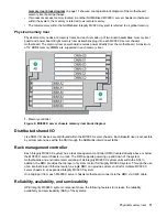
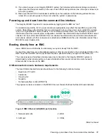
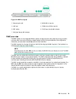
The following connectors and LEDs are also located on the front panel of the RMC:
•
Stack connector
—38 circuit ipass connector used to expand the system management network by
connecting to a second RMC
•
WAN port
—RJ45 port used to connect to the customer’s LAN or an in-rack administration node
•
AUX port
—RJ45 port currently is non-functional (reserved for future use)
•
CNSL port
—micro USB B port used for a local console/server connection
•
RST switch
—recessed push button switch used for reset of the RMC. The switch is accessed by
inserting a small screw driver or similar device through an opening in the front panel
•
PG LED
—green power good LED is illuminated when the correct power levels are present in the RMC
•
HB LED
—green heart beat LED flashes when the RMC is functioning normally
RMC functions
25


