background image


Hardware options installation  39 


Populate drive bays, based on the drive numbering sequence. Start from the drive bay with the 

lowest device number ("

Drive numbering

" on page 

13

). 


All drives grouped into the same drive array must meet the following criteria: 

o


They must be either all SAS or all SATA. 

o


They must be either all hard drives or all solid state drives. 

o


Drives should be the same capacity to provide the greatest storage space efficiency when drives 

are grouped together into the same drive array. 


Installing a non-hot-plug drive 


CAUTION:

  To prevent improper cooling and thermal damage, do not operate the server 

unless all bays are populated with either a component or a blank. 


To install the component: 

1. 

Power down the server (on page 

16

). 

2. 

Remove all power: 

a. 

Disconnect each power cord from the power source. 

b. 

Disconnect each power cord from the server. 

3. 

Remove the tower bezel ("

Remove the bezel

" on page 

17

). 

4. 

Remove the access panel (on page 

18

). 

5. 

Remove the air baffle (on page 

20

). 

6. 

Disconnect all cables connected to any installed drives. 

7. 

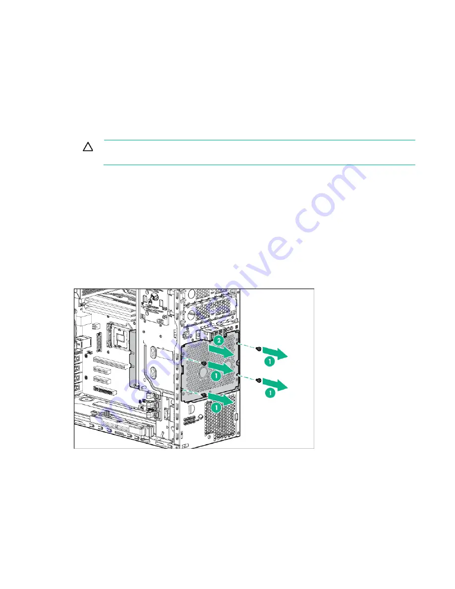
Remove the installed drive cage assembly. 


8. 

Use the screws on the drive cage to install the drives. 

Summary of Contents for HPE ProLiant ML30 Gen9

Page 1: ...ho installs administers and troubleshoots servers and storage systems Hewlett Packard Enterprise assumes you are qualified in the servicing of computer equipment and trained in recognizing hazards in products with hazardous energy levels Part Number 825546 001 December 2015 Edition 1 ...

Page 2: ...o third party websites take you outside the Hewlett Packard Enterprise website Hewlett Packard Enterprise has no control over and is not responsible for information outside the Hewlett Packard Enterprise website Linux is the registered trademark of Linus Torvalds in the U S and other countries Microsoft and Windows are U S registered trademarks of the Microsoft group of companies MicroSD is a trad...

Page 3: ... requirements 21 Temperature requirements 21 Power requirements 22 Electrical grounding requirements 22 Server warnings and cautions 22 Identifying the contents of the server shipping carton 23 Installing hardware options 23 Installing the operating system 23 Powering on and selecting boot options in UEFI Boot Mode 24 Registering the server 24 Hardware options installation 25 Introduction 25 Front...

Page 4: ...I O module cabling 71 FBWC cabling 71 Smart Storage Battery cabling 72 System fan cabling 72 Front PCI fan cabling 73 Power supply cabling 73 350W E1 0 E2 0 non hot plug power supply 73 Redundant power supply cabling 75 Software and configuration utilities 77 Server mode 77 Product QuickSpecs 77 HPE iLO 77 Active Health System 78 RESTful API support for iLO 79 Integrated Management Log 79 HPE Insi...

Page 5: ...ment 92 Warranty and regulatory information 94 Warranty information 94 Regulatory information 94 Safety and regulatory compliance 94 Belarus Kazakhstan Russia marking 94 Turkey RoHS material content declaration 95 Ukraine RoHS material content declaration 95 Specifications 96 Environmental specifications 96 Server specifications 96 Power supply specifications 96 HPE 350 W Power Supply E star 1 0 9...

Page 6: ...Component identification 6 Component identification Front panel components Item Description 1 Media drive bays 2 USB 3 0 connectors 3 Drive cage bay Front panel LEDs and buttons ...

Page 7: ...aneously a power fault has occurred For more information see Front panel LED power fault codes on page 7 Facility power is not present power cord is not attached no power supplies are installed power supply failure has occurred or the power button cable is disconnected If the health LED indicates a degraded or critical state review the system IML or use iLO to review the system health status For m...

Page 8: ...ared iLO connector 5 PCIe slot 4 PCIe3 x16 16 8 4 1 full length 6 PCIe slot 3 PCIe3 x4 1 full length 7 PCIe slot 2 PCIe3 x4 1 full length 8 PCIe slot 1 PCIe3 x8 4 1 half length 9 USB 3 0 connectors 10 USB 2 0 connectors 11 Video connector For more information on the expansion slot specifications see PCIe expansion slot definitions on page 11 ...

Page 9: ...nd Remote management or firmware upgrade in progress 4 flashes per second iLO manual reboot sequence initiated 8 flashes per second iLO manual reboot sequence in progress Off Deactivated 2 NIC link LED Green Network link Off No network link 3 NIC activity LED Solid green Link to network Flashing green Network active Off No network activity ...

Page 10: ... 0 connector for tape drive 11 Internal USB 2 0 connector 12 microSD card slot 13 Front PCI fan connector 14 Front panel USB connector 15 Front panel I O connector 16 Front panel USB connector 17 Smart Storage Battery connector 18 Storage backup power connector 19 NMI header 20 PCIe slot 1 PCIe3 x8 4 1 half length 21 System maintenance switch 22 PCIe slot 2 PCIe3 x4 1 full length 23 PCIe slot 3 PC...

Page 11: ...ots are numbered 1 through 4 Letters are used for AMP mode DIMM ordering PCIe expansion slot definitions Slot number Type Length Height Connector link width Negotiable link width 1 PCIe3 Half Full x8 4 1 2 PCIe3 Full Full x4 1 3 PCIe3 Full Full x4 1 4 PCIe3 Full Full x16 16 8 4 1 System maintenance switch Position Default Function S1 Off Off iLO security is enabled On iLO security is disabled S2 O...

Page 12: ...led Do not use the B140i controller when the server is in Legacy BIOS Boot Mode NMI functionality An NMI crash dump creates a crash dump log before resetting a system which is not responding Crash dump log analysis is an essential part of diagnosing reliability problems such as failures of operating systems device drivers and applications Many crashes freeze a system and the only available action ...

Page 13: ...Component identification 13 Drive numbering Four bay LFF non hot plug drive numbering Four bay LFF hot plug drive numbering ...

Page 14: ...ng green Drive activity Off No drive activity 3 Do not remove Solid white Do not remove the drive Removing the drive causes one or more of the logical drives to fail Off Removing the drive does not cause a logical drive to fail 4 Drive status Solid green The drive is a member of one or more logical drives Flashing green The drive is rebuilding or performing a RAID migration strip size migration ca...

Page 15: ...SAS connectors operate in AHCI or Legacy mode Under this condition The drives cannot be a part of a hardware RAID or a logical drive The Locate Drive status and Do not remove LEDs of the affected drives are disabled Use BIOS Platform Configuration RBSU in the UEFI System Utilities HPE UEFI System Utilities on page 82 to enable or disable the B140i controller System Configuration BIOS Platform Conf...

Page 16: ... IMPORTANT When the server is in standby mode auxiliary power is still being provided to the system To power down the server use one of the following methods Press and release the Power On Standby button This method initiates a controlled shutdown of applications and the OS before the server enters standby mode Press and hold the Power On Standby button for more than 4 seconds to force the server ...

Page 17: ...d media bays It must be unlocked to remove the access panel The bezel must remain closed during normal server operations 1 Unlock the bezel 2 Open the bezel 3 Pull the bezel away from the front chassis Install the access panel 1 Power down the server on page 16 2 Remove all power a Disconnect each power cord from the power source ...

Page 18: ...system components to cool before touching them CAUTION For proper cooling do not operate the server without the access panel baffles expansion slot covers or blanks installed If the server supports hot plug components minimize the amount of time the access panel is open 1 Power down the server on page 16 2 Remove all power a Disconnect each power cord from the power source b Disconnect each power ...

Page 19: ... power source b Disconnect each power cord from the server 3 Remove the bezel on page 17 4 Place the server on its side with the access panel facing up 5 Remove the access panel on page 18 6 Insert the tabs on the baffle into the slots on the rear chassis 7 Push the front end of the baffle into the chassis 8 Install the access panel on page 17 9 Install the bezel on page 16 ...

Page 20: ...If the server supports hot plug components minimize the amount of time the access panel is open 1 Power down the server on page 16 2 Remove all power a Disconnect each power cord from the power source b Disconnect each power cord from the server 3 Remove the bezel on page 17 4 Place the server on its side with the access panel facing up 5 Remove the access panel on page 18 6 Remove the air baffle ...

Page 21: ... o Linux operating systems o ProLiant Essentials HPE SIM and RDP Integrated hardware and software support o Critical Service o Proactive 24 o Support Plus o Support Plus 24 Startup and implementation services for both hardware and software For more information on Care Pack Services see the Hewlett Packard Enterprise website http www hpe com services carepack Optimum environment When installing the...

Page 22: ... server must be grounded properly for proper operation and safety In the United States you must install the equipment in accordance with NFPA 70 1999 Edition National Electric Code Article 250 as well as any local and regional building codes In Canada you must install the equipment in accordance with Canadian Standards Association CSA C22 1 Canadian Electrical Code In all other countries you must ...

Page 23: ... operating system This ProLiant server does not ship with provisioning media Everything needed to manage and install the system software and firmware is preloaded on the server To operate properly the server must have a supported operating system installed For the latest information on operating system support see the Hewlett Packard Enterprise website http www hpe com info supportos Attempting to...

Page 24: ...ons in UEFI Boot Mode On servers operating in UEFI Boot Mode the boot controller and boot order are set automatically 1 Press the Power On Standby button 2 During the initial boot o To modify the server configuration ROM default settings press the F9 key in the ProLiant POST screen to enter the UEFI System Utilities screen By default the System Utilities menus are in the English language o If you ...

Page 25: ...tallation procedure Improper grounding can cause electrostatic discharge Front PCI fan option For more information about product features specifications options configurations and compatibility see the product QuickSpecs on the Hewlett Packard Enterprise website http www hpe com info qs To install the component 1 Power down the server on page 16 2 Remove all power a Disconnect each power cord from...

Page 26: ...e server on page 16 Slim optical disk drive option For more information about product features specifications options configurations and compatibility see the product QuickSpecs on the Hewlett Packard Enterprise website http www hpe com info qs To install the component 1 Power down the server on page 16 2 Remove all power a Disconnect each power cord from the power source b Disconnect each power c...

Page 27: ... Remove the media drive bay blank 8 Remove the EMI shield 9 Install the slim optical disk drive into the drive cage a Slide the slim optical disk drive into the drive cage b Install the two T 15 screws and secure the drive into the cage ...

Page 28: ...s installation 28 c Install four M3 screws from the server front panel to each side of the drive cage 10 Connect the SATA Power Y cables to the rear of the drive then route the cable through the clip on the drive cage ...

Page 29: ... c Route the SATA cable through the cable management clips If a redundant power supply is installed connect the 4 pin to 4 pin extension cable to the redundant power supply cable For cable routing information see Slim optical disk drive cabling on page 70 13 Install the air baffle on page 19 14 Install the access panel on page 17 15 Install the bezel on page 16 16 Return the server to an upright p...

Page 30: ...wer down the server on page 16 2 Remove all power a Disconnect each power cord from the power source b Disconnect each power cord from the server 3 Remove the bezel on page 17 4 Place the server on its side with the access panel facing up 5 Remove the access panel on page 18 6 Remove the air baffle on page 20 7 Disconnect all power supply cables from the system board drive cages and devices 8 Remo...

Page 31: ...ith four screws 10 Connect the power supply cables a 24 pin power cable to the system board b 4 pin power cable to the system board c 8 pin power cable to the drive cage backplane or non hot plug drive power cable o Four bay LFF non hot plug drive configuration ...

Page 32: ...ezel on page 16 14 Return the server to an upright position 15 Connect each power cord to the server 16 Connect each power cord to the power source 17 Power up the server on page 16 Redundant power supply enablement option For more information about product features specifications options configurations and compatibility see the product QuickSpecs on the Hewlett Packard Enterprise website http www...

Page 33: ...all the component 1 Power down the server on page 16 2 Remove all power a Disconnect each power cord from the power source b Disconnect each power cord from the server 3 Remove the bezel on page 17 4 Place the server on its side with the access panel facing up 5 Remove the access panel on page 18 6 Remove the air baffle on page 20 7 Disconnect all power supply cables from the system board drive ca...

Page 34: ...PS cage a Slide the RPS cage into the chassis b Secure the RPS cage with four screws 11 Install the RPS backplane module a Route the power supply cables through the media drive bays b Align the pins on the chassis and slide the RPS backplane module through the media drive bays ...

Page 35: ...CAUTION The default and redundant power supplies in the server must have the same output power capacity Verify that all power supplies have the same part number and label color The system becomes unstable and might shut down if it detects mismatched power supplies 13 To enable the redundant power supply configuration ...

Page 36: ... a second power input module into the upper bay 14 Connect the power supply cables a 24 pin power cable to the system board b 4 pin power cable to the system board c 10 pin to 8 pin power cable to the drive cage backplane or non hot plug drive cable d RPS cable to the system board ...

Page 37: ...Hardware options installation 37 Four bay LFF non hot plug drive configuration Four bay LFF hot plug drive configuration ...

Page 38: ... The default drive cage may be replaced with an optional four bay LFF hot plug drive cage to support up to four hot plug LFF drives The default drive cage may alternatively be replaced with an optional eight bay SFF hot plug drive cage to support up to eight hot plug SFF drives If the optional eight bay SFF drive cage is installed the server supports four SFF drives using the embedded storage cont...

Page 39: ...ogether into the same drive array Installing a non hot plug drive CAUTION To prevent improper cooling and thermal damage do not operate the server unless all bays are populated with either a component or a blank To install the component 1 Power down the server on page 16 2 Remove all power a Disconnect each power cord from the power source b Disconnect each power cord from the server 3 Remove the ...

Page 40: ...Hardware options installation 40 9 Install drives into the drive cage 10 Install the drive cage into the chassis ...

Page 41: ... Connect each power cord to the server 16 Connect each power cord to the power source 17 Power up the server on page 16 Installing a hot plug drive CAUTION To prevent improper cooling and thermal damage do not operate the server unless all bays are populated with either a component or a blank To install the component 1 Remove the tower bezel Remove the bezel on page 17 2 Remove the drive blank ...

Page 42: ...lett Packard Enterprise website http www hpe com info qs Host Bus Adapter Mini SAS cable option For more information about product features specifications options configurations and compatibility see the product QuickSpecs on the Hewlett Packard Enterprise website http www hpe com info qs To install the component 1 Back up all server data 2 Power down the server on page 16 3 Remove all power a Dis...

Page 43: ...ing the H240 H241 Host Bus Adapter in slot 4 for optimal performance 11 Install the air baffle on page 19 12 Install the access panel on page 17 13 Install the bezel on page 16 14 Return the server to an upright position 15 Connect each power cord to the server 16 Connect each power cord to the power source 17 Power up the server on page 16 Smart Array Controller Mini SAS cable option For more inf...

Page 44: ...nection 10 Install the Smart Array Controller Installing a storage controller and FBWC module options on page 45 Storage controllers may be installed in PCIe slot 1 or 4 HPE recommends installing the P440 P441 Smart Array Controller in slot 4 for optimal performance 11 Install the air baffle on page 19 12 Install the access panel on page 17 13 Install the bezel on page 16 14 Return the server to a...

Page 45: ...n process writes the preserved data to the storage drives CAUTION The cache module connector does not use the industry standard DDR3 mini DIMMs Do not use the controller with cache modules designed for other controller models because the controller can malfunction and you can lose data Also do not transfer this cache module to an unsupported controller model because you can lose data CAUTION To pr...

Page 46: ...ss panel facing up 6 Remove the access panel on page 18 7 Remove the air baffle on page 20 8 If you intend to use an FBWC module install the module on the storage controller a If you are installing a Smart Array P440 Controller remove the air scoop b Connect the cache module backup power cable to the module ...

Page 47: ...nstallation 47 c Install the cache module on the storage controller 9 Locate the appropriate PCIe slot on the system board System board components on page 10 10 Open the PCIe slot cover retainer and remove the slot blank ...

Page 48: ...s panel on page 17 18 Install the bezel on page 16 19 Return the server to an upright position 20 Connect each power cord to the server 21 Connect each power cord to the power source 22 Power up the server on page 16 Installing a Smart Storage Battery For more information about product features specifications options configurations and compatibility see the product QuickSpecs on the Hewlett Packar...

Page 49: ...Hardware options installation 49 7 Remove the slot covers 8 Install the Smart Storage Battery holders ...

Page 50: ...Drive enablement option For more information about product features specifications options configurations and compatibility see the product QuickSpecs on the Hewlett Packard Enterprise website http www hpe com info qs Each drive enablement option allows adding an additional SATA LFF drive to the server To install the component 1 Back up all server data 2 Power down the server on page 16 3 Remove a...

Page 51: ...Hardware options installation 51 8 Remove the EMI shield 9 Install the drive into the drive carrier and secure it with four T 15 screws included with the option ...

Page 52: ...Secure M3 screws to the drive carrier M3 screws can be found on the server front panel 11 Insert the drive carrier into the media drive bay until the carrier locks into place 12 Connect the drive cables a Connect and secure the SATA cable ...

Page 53: ...mpatibility see the product QuickSpecs on the Hewlett Packard Enterprise website http www hpe com info qs To install the component 1 Power down the server on page 16 2 Remove all power a Disconnect each power cord from the power source b Disconnect each power cord from the server 3 Remove the bezel on page 17 4 Place the server on its side with the access panel facing up 5 Remove the access panel ...

Page 54: ...installation 54 8 Remove the non hot plug drive cage 9 Install the drive cage assembly 10 Connect the drive backplane cables a Connect one end of the Mini SAS cable to the backplane and the other end to the system board ...

Page 55: ...baffle on page 19 13 Install the access panel on page 17 14 Install the bezel on page 16 15 Return the server to an upright position 16 Connect each power cord to the server 17 Connect each power cord to the power source 18 Power up the server on page 16 19 Determine the status of the drive from the drive LEDs Hot plug drive LED definitions on page 14 Eight bay SFF hot plug drive cage option For m...

Page 56: ...S cable from the system board b Disconnect the power cable from the power supply c Disconnect the drive cables from the rear of the drives 8 Remove the non hot plug drive cage 9 Install the drive cage assembly 10 Connect the drive backplane cables a Connect one end of the Mini SAS cable to the backplane and the other end to the system board b Connect the power cable to the backplane ...

Page 57: ...are options installation 57 Mini SAS cable connected from backplane connector 1 to the system board 4 drives supported Mini SAS Y cable connected from backplane connectors 1 and 2 to a Smart Array controller ...

Page 58: ...rive bays based on the drive numbering sequence Start from the drive bay with the lowest device number Drive numbering on page 13 Port 1 of the hot plug drive backplane supports drives 1 to 4 Port 2 of the hot plug drive backplane supports drives 5 to 8 12 Install a front PCI fan Front PCI fan option on page 25 13 Install the air baffle on page 19 14 Install the access panel on page 17 15 Install ...

Page 59: ... configuration requirements are based on these classifications A single rank DIMM has one set of memory chips that is accessed while writing to or reading from the memory A dual rank DIMM is similar to having two single rank DIMMs on the same module with only one rank accessible at a time A quad rank DIMM is effectively two dual rank DIMMs on the same module Only one rank is accessible at a time T...

Page 60: ...eral DIMM slot population guidelines The server has four DIMM slots The server supports two channels with two DIMM slots per channel o Memory channel 1 consists of the two DIMMs that are closest to the processor o Memory channel 2 consists of the two DIMMs that are farthest from the processor A white DIMM slot indicates the first slot of a channel 2 A 4 B Memory speed support depends on the type o...

Page 61: ...ess panel on page 17 12 Install the bezel on page 16 13 Return the server to an upright position 14 Connect each power cord to the server 15 Connect each power cord to the power source 16 Power up the server on page 16 Use the BIOS Platform Configuration RBSU in the UEFI System Utilities to configure the memory mode Setting up the HPE PS1810 24G Switch optional If you intend to use the server with...

Page 62: ...t is being used Initially solid green to indicate successful connection and then flashing green to indicate active communication with the network o Fault LED Remains off to indicate successful Self Test completion For more information on the location of the switch LEDs and their behavior during the Self Test process see the switch documentation Completing the switch setup After the Ethernet cable ...

Page 63: ...des a TPM with the spare system board Any attempt to remove an installed TPM from the system board breaks or disfigures the TPM security rivet Upon locating a broken or disfigured rivet on an installed TPM administrators should consider the system compromised and take appropriate measures to ensure the integrity of the system data When using BitLocker always retain the recovery key password The re...

Page 64: ... and take appropriate measures to ensure the integrity of the system data 7 Install the TPM board Press down on the connector to seat the board System board components on page 10 8 Install the TPM security rivet by pressing the rivet firmly into the system board 9 Install the air baffle on page 19 10 Install the access panel on page 17 11 Install the bezel on page 16 12 Return the server to an upr...

Page 65: ...ress the Enter key 4 Select Enabled to enable the TPM and BIOS secure startup The TPM is fully functional in this mode 5 Press the F10 key to save your selection 6 When prompted to save the change in System Utilities press the Y key 7 Press the ESC key to exit System Utilities Then press the Enter key when prompted to reboot the server The server then reboots a second time without user input Durin...

Page 66: ...al components see the white paper on high density deployment at the Hewlett Packard Enterprise website http www hpe com products servers platforms CAUTION When routing cables always be sure that the cables are not in a position where they can be pinched or crimped Storage cabling Drive enablement option cabling Drive enablement option to 350W power supply Item Description 1 SATA cable 2 Drive powe...

Page 67: ...lement option to redundant power supply Item Description 1 SATA cable 2 Drive power cable Four bay LFF non hot plug drive cage cabling Item Description 1 Power cable 2 10 pin to 8 pin power extension cable 3 Mini SAS cable ...

Page 68: ...ive cage cabling Item Description 1 Mini SAS cable 2 Power cable Eight bay SFF hot plug drive cage cabling Eight bay SFF hot plug drive cage cabling to system board supports up to 4 drives Item Description 1 Mini SAS cable 2 Power cable ...

Page 69: ...g to Smart Array controller supports up to 8 drives Item Description 1 Mini SAS Y cable 2 Power cable Eight bay SFF hot plug drive cage cabling to host bus adapter supports up to 8 drives Item Description 1 Mini SAS cable 2 Power cable 3 Mini SAS cable ...

Page 70: ...tem Description 1 Optical disk drive power cable 2 SATA cable 3 4 pin power cable to 4 pin power supply extension cable Slim optical disk drive to redundant power supply Item Description 1 Optical disk drive power cable 2 SATA cable 3 4 pin power cable to 4 pin power supply extension cable ...

Page 71: ...Cabling 71 Front I O module cabling Item Description 1 Front I O cable 2 Front USB cable 3 Front USB cable 4 Ambient temperature sensor cable shared connector with front I O cable FBWC cabling ...

Page 72: ...Cabling 72 Smart Storage Battery cabling System fan cabling ...

Page 73: ...ling Power supply cabling 350W E1 0 E2 0 non hot plug power supply Four bay LFF non hot plug drive configuration Item Description 1 8 pin drive power cable 2 Non hot plug drive power cable 3 4 pin power cable 4 24 pin power cable ...

Page 74: ...g drive configuration Item Description 1 8 pin drive power cable 2 4 pin power cable 3 24 pin power cable Eight bay SFF hot plug drive configuration Item Description 1 8 pin drive power cable 2 4 pin power cable 3 24 pin power cable ...

Page 75: ...ion 1 24 pin power supply cable 2 4 pin power supply cable 3 RPS sideband signal cable 4 10 pin to 8 pin power supply cable Four bay LFF hot plug drive configuration Item Description 1 24 pin power supply cable 2 4 pin power supply cable 3 RPS sideband signal cable 4 10 pin to 8 pin power supply cable ...

Page 76: ...Cabling 76 Eight bay SFF hot plug drive configuration Item Description 1 24 pin power supply cable 2 4 pin power supply cable 3 RPS sideband signal cable 4 10 pin to 8 pin power supply cable ...

Page 77: ...ine and Offline FWUPDATE utility on page 87 Offline Product QuickSpecs For more information about product features specifications options configurations and compatibility see the product QuickSpecs on the Hewlett Packard Enterprise website http www hpe com info qs HPE iLO The iLO subsystem is a standard component of ProLiant servers that simplifies initial server setup server health monitoring pow...

Page 78: ...ND size and embedded user partition vary depending on the server model For a complete list of supported features and functionality see the iLO 4 QuickSpecs on the Hewlett Packard Enterprise website http www hpe com info Quickspecs iLO Active Health System The HPE Active Health System provides the following features Combined diagnostics tools scanners Always on continuous monitoring for increased s...

Page 79: ...web server to GET and PATCH JSON formatted data and to configure supported iLO and server settings such as the UEFI BIOS settings HPE iLO 4 supports the RESTful API with ProLiant Gen8 and later servers For more information about the RESTful API see the Hewlett Packard Enterprise website http www hpe com support restfulinterface docs Integrated Management Log The IML records hundreds of events and ...

Page 80: ...website http www hpe com info insightremotesupport docs Insight Online HPE Insight Online is a capability of the Support Center portal Combined with Insight Remote Support central connect or Insight Online direct connect it automatically aggregates device health asset and support information with contract and warranty information and then secures it in a single personalized dashboard that is viewa...

Page 81: ...on ProLiant servers This functionality supports operating systems that are supported by the server For operating systems supported by the server see the Hewlett Packard Enterprise website http www hpe com info supportos If a significant change occurs between data gathering intervals the survey function marks the previous information and overwrites the survey data files to reflect the latest change...

Page 82: ...em or in an offline mode where the server is booted to an operating system included on the ISO file so that the server can be updated automatically with no user interaction or updated in interactive mode For more information or to download SPP see one of the following pages on the Hewlett Packard Enterprise website Service Pack for ProLiant download page http www hpe com info spp docs Smart Update...

Page 83: ...have been restored Default configuration settings are sufficient for typical server operations however you can modify configuration settings as needed The system prompts you for access to the System Utilities each time the system is powered up Flexible boot control This feature enables you to do the following Add Boot Options o Browse all FAT16 and FAT32 file systems o Select an X64 UEFI applicati...

Page 84: ...that have an appropriate digital signature can execute during the boot process Only operating systems that support Secure Boot and have an EFI boot loader signed with one of the authorized keys can boot when Secure Boot is enabled For more information about supported operating systems see the UEFI system utilities and shell release notes on the Hewlett Packard Enterprise website http www hpe com i...

Page 85: ...nel This value should always match the serial number located on the chassis 4 Press the Enter key to clear the warning 5 Enter the serial number and press the Enter key 6 Select Product ID The following warning appears Warning The Product ID should ONLY be modified by qualified service personnel This value should always match the Product ID located on the chassis 7 Enter the product ID and press t...

Page 86: ...the Legacy Boot Mode The pre OS behavior of the USB ports is configurable in System Utilities so that the user can change the default operation of the USB ports For more information see the HPE UEFI System Utilities User Guide for HPE ProLiant Gen9 Servers on the Hewlett Packard Enterprise website http www hpe com info uefi docs External USB functionality Hewlett Packard Enterprise provides extern...

Page 87: ... Enterprise Support Center website http www hpe com support hpesc 2 Save the FWUPDATE flash components to a USB key 3 Set the boot order so the USB key will boot first using one of the following options o Configure the boot order so the USB key is the first bootable device o Press F11 Boot Menu when prompted during system boot to access the One Time Boot Menu This menu allows you to select the boo...

Page 88: ...n either boot mode update the firmware 1 Access the System ROM Flash Binary component for your server from the Hewlett Packard Enterprise Support Center website http www hpe com support hpesc When searching for the component always select OS Independent to find the component 2 Copy the binary file to a USB media or iLO virtual media 3 Attach the media to the server 4 During POST press F9 to enter ...

Page 89: ...ownload individual drivers firmware or other systems software components from the server product page in the Hewlett Packard Enterprise Support Center website http www hpe com support hpesc Operating System Version Support For information about specific versions of a supported operating system refer to the operating system support matrix http www hpe com info ossupport Version control The VCRM and...

Page 90: ...us the leading industry standard operating systems Let us work proactively with you to prevent problems Our flexible choices of hardware and software support coverage windows and response times help resolve problems faster reduce unplanned outages and free your staff for more important tasks For more information see the Hewlett Packard Enterprise website http www hpe com services support Tap into ...

Page 91: ... Gen9_TSG_es German http www hpe com support Gen9_TSG_de Japanese http www hpe com support Gen9_TSG_ja Simplified Chinese http www hpe com support Gen9_TSG_zh_cn The HPE ProLiant Gen9 Troubleshooting Guide Volume II Error Messages provides a list of error messages and information to assist with interpreting and resolving error messages on ProLiant servers and server blades To view the guide select...

Page 92: ...n fire or water Replace only with the spare designated for this product To remove the component 1 Power down the server on page 16 2 Remove all power a Disconnect each power cord from the power source b Disconnect each power cord from the server 3 Do the following a Unlock the tower bezel Remove the bezel on page 17 b Remove the tower bezel Remove the bezel on page 17 4 Place the server on its sid...

Page 93: ...battery replacement 93 To replace the component reverse the removal procedure For more information about battery replacement or proper disposal contact an authorized reseller or an authorized service provider ...

Page 94: ...ory information Safety and regulatory compliance For important safety environmental and regulatory information see Safety and Compliance Information for Server Storage Power Networking and Rack Products available at the Hewlett Packard Enterprise website http www hpe com support Safety Compliance EnterpriseProducts Belarus Kazakhstan Russia marking Manufacturer and Local Representative Information...

Page 95: ...dicates the year counting from within each new decade with 2000 as the starting point for example 238 2 for 2002 and 38 for the week of September 9 In addition 2010 is indicated by 0 2011 by 1 2012 by 2 2013 by 3 and so forth YYWW where YY indicates the year using a base year of 2000 for example 0238 02 for 2002 and 38 for the week of September 9 Turkey RoHS material content declaration Ukraine Ro...

Page 96: ... cm 18 70 in Width 17 50 cm 6 89 in Weight full load approximate values Four bay LFF non hot plug model 13 1 kg 28 82 lb Four bay LFF hot plug drive model 13 6 kg 29 92 lb Eight bay SFF hot plug drive model 12 4 kg 27 28 lb Power supply specifications Depending on installed options the server is configured with one of the following power supplies HPE 350 W Power Supply E star 1 0 HPE 350 W Power S...

Page 97: ...ments Rated input voltage 100 V AC to 240 V AC Rated input frequency 47 Hz to 63 Hz Rated input current 5 A to 2 5 A Rated input power 412 W at 115 V AC input 412 W at 230 V AC input Efficiency No less than 85 at 100 load No less than 88 at 50 load No less than 85 at 20 load Power supply output Rated steady state power 350 W at 115 V AC input 350 W at 230 V AC input Maximum peak power 350 W at 115...

Page 98: ...Power supply output Rated steady state power 460 W at 100 V to 120 V AC input 460 W at 200 V to 240 V AC input Maximum peak power 460 W at 100 V to 120 V AC input 460 W at 200 V to 240 V AC input Rated output power 460 W ...

Page 99: ... hpesc Contact Hewlett Packard Enterprise Worldwide http www hpe com assistance Subscription Service Support Alerts http www hpe com support e updates Software Depot http www hpe com support softwaredepot Customer Self Repair http www hpe com support selfrepair Insight Remote Support http www hpe com info insightremotesupport docs Serviceguard Solutions for HP UX http www hpe com info hpux service...

Page 100: ... délais de réparation et faciliter le remplacement des pièces défectueuses Si pendant la période de diagnostic Hewlett Packard Enterprise ou ses partenaires ou mainteneurs agréés détermine que la réparation peut être effectuée à l aide d une pièce CSR Hewlett Packard Enterprise vous l envoie directement Il existe deux catégories de pièces CSR Obligatoire Pièces pour lesquelles la réparation par le...

Page 101: ...entro quattro ore è offerta con un supplemento di costo solo in alcune zone In caso di necessità si può richiedere l assistenza telefonica di un addetto del centro di supporto tecnico Hewlett Packard Enterprise Nel materiale fornito con una parte di ricambio CSR Hewlett Packard Enterprise specifica se il cliente deve restituire dei component Qualora sia richiesta la resa ad Hewlett Packard Enterpr...

Page 102: ... la fase de diagnóstico Hewlett Packard Enterprise o los proveedores o socios de servicio de Hewlett Packard Enterprise identifica que una reparación puede llevarse a cabo mediante el uso de un componente CSR Hewlett Packard Enterprise le enviará dicho componente directamente para que realice su sustitución Los componentes CSR se clasifican en dos categorías Obligatorio componentes cuya reparación...

Page 103: ...e onderdelen worden in de geïllustreerde onderdelencatalogus aangemerkt met Nee Afhankelijk van de leverbaarheid en de locatie worden CSR onderdelen verzonden voor levering op de eerstvolgende werkdag Levering op dezelfde dag of binnen vier uur kan tegen meerkosten worden aangeboden indien dit mogelijk is gezien de locatie Indien assistentie is gewenst belt u het Hewlett Packard Enterprise Support...

Page 104: ... ser feita mediante uma taxa adicional Se precisar de auxílio entre em contato com o Centro de suporte técnico da Hewlett Packard Enterprise para que um técnico o ajude por telefone A Hewlett Packard Enterprise especifica nos materiais fornecidos com a peça CSR de reposição se a peça com defeito deve ser devolvida à Hewlett Packard Enterprise Nos casos em que isso for necessário é preciso enviar a...

Page 105: ...Support and other resources 105 ...

Page 106: ...atic secure submission of hardware event notifications to Hewlett Packard Enterprise which will initiate a fast and accurate resolution based on your product s service level Hewlett Packard Enterprise strongly recommends that you register your device for remote support For more information and device support details go to the Insight Remote Support website http www hpe com info insightremotesuppor...

Page 107: ...utomatic Server Recovery BSMI Bureau of Standards Metrology and Inspection CE Conformité Européenne European Conformity CSA Canadian Standards Association CSR Customer Self Repair EMI electromagnetic interference FBWC flash backed write cache FCC Federal Communications Commission HP SUM HP Smart Update Manager HPE SIM HPE Systems Insight Manager ...

Page 108: ...tion for Standardization LFF large form factor LRDIMM load reduced dual in line memory module NMI nonmaskable interrupt NVRAM nonvolatile memory PCIe Peripheral Component Interconnect Express PDU power distribution unit POST Power On Self Test RBSU ROM Based Setup Utility RDIMM registered dual in line memory module RDP Rapid Deployment Pack RF radio frequency ...

Page 109: ...ervice Pack for ProLiant TMRA recommended ambient operating temperature TPM Trusted Platform Module UDIMM unregistered dual in line memory module UEFI Unified Extensible Firmware Interface UID unit identification USB universal serial bus VCA Version Control Agent VCRM Version Control Repository Manager xHCI Extensible Host Controller Interface ...

Page 110: ...tion send any errors suggestions or comments to Documentation Feedback mailto docsfeedback hpe com When submitting your feedback include the document title part number edition and publication date located on the front cover of the document For online help content include the product name product version help edition and publication date located on the legal notices page ...

Page 111: ...7 81 error messages 91 European Union notice 94 F FBWC cabling 66 features 6 85 Federal Communications Commission FCC notice 94 firmware 87 89 front panel components 6 G grounding requirements 22 H hardware options installation 25 health driver 86 Hot plug SAS SATA hard drive cabling 66 HP Smart Update Manager overview 77 82 HPE Insight Diagnostics 79 80 81 HPE Insight Remote Support software 79 8...

Page 112: ...olkit 77 82 security 86 serial number 85 series number 94 server features and options 25 Server mode 77 server setup 21 24 87 server specifications 96 Service Packs 82 shipping carton contents 23 Smart Update Manager 77 82 software 77 89 space and airflow requirements 21 specifications 96 specifications environmental 96 specifications power 96 specifications server 96 storage controller 44 support...

Reviews: