background image

Extend the server from the rack.

Remove the server from the rack.

5. Remove the access panel.

6. Remove the air baffle.

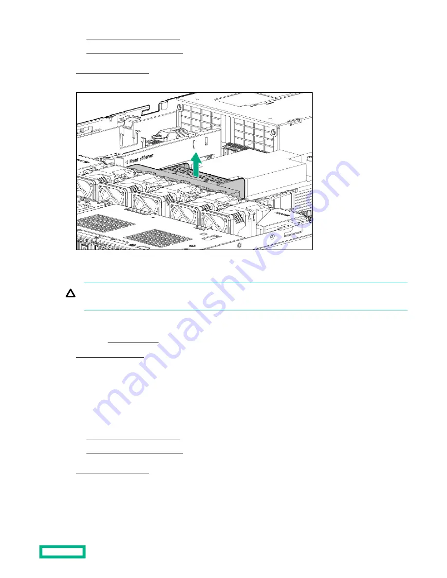
Remove the primary riser cage

CAUTION: To prevent damage to the server or expansion boards, power down the server, and disconnect all power
cords before removing or installing the PCIe riser board.

Procedure

1. If installed, remove the bezel.

2. Power down the server.

3. Remove all power:

a. Disconnect each power cord from the power source.

b. Disconnect each power cord from the server.

4. Do one of the following:

Extend the server from the rack.

Remove the server from the rack.

5. Remove the access panel.

6. If present, disconnect all cables from the expansion board.

7. Remove the primary riser cage.

Removal and replacement procedures

36

Summary of Contents for HPE ProLiant DL325

Page 1: ...ion and maintenance procedures diagnostic tools specifications and requirements for hardware components and software This guide is for an experienced service technician Hewlett Packard Enterprise assumes that you are qualified in the servicing of computer equipment trained in recognizing hazards in products and are familiar with weight and stability precautions ...

Page 2: ...a for Commercial Items are licensed to the U S Government under vendor s standard commercial license Links to third party websites take you outside the Hewlett Packard Enterprise website Hewlett Packard Enterprise has no control over and is not responsible for information outside the Hewlett Packard Enterprise website Acknowledgments Microsoft and Windows are either registered trademarks or tradem...

Page 3: ... parts 12 AMD EPYC 7xx2 processor spare parts 13 Riser board spare parts 13 System battery spare part 13 System board assembly spare parts 14 Server options 14 Energy pack spare parts 15 Backplane board spare parts 15 Chassis intrusion detection switch spare part 15 Serial port cable spare part 15 GPU holder spare part 15 iLO Service Port spare part 16 Cable spare parts 16 HPE Trusted Platform Mod...

Page 4: ... Array type a modular controller 57 Removing and replacing an energy pack 58 Removing and replacing the energy pack holder 59 Removing and replacing the optical drive blank 60 Removing and replacing the optical drive 62 Removing and replacing a chassis ear 64 Removing and replacing the LFF front I O assembly 65 Removing and replacing the SFF front I O assembly 66 Removing and replacing the iLO Ser...

Page 5: ...aunching the Embedded UEFI Shell 107 iLO Service Port 108 Intelligent Provisioning 108 Intelligent Provisioning operation 109 HPE Insight Remote Support 110 HPE InfoSight for servers 110 USB support 110 External USB functionality 110 HPE Smart Storage Administrator 111 Component identification 112 Front panel components 112 Serial number iLO information pull tab 113 Front panel LEDs and buttons 11...

Page 6: ...le routing M 2 SSD 150 Cable routing Controller backup power cable 151 Cable routing Energy pack 153 Specifications 154 Environmental specifications 154 Mechanical specifications 155 Power supply specifications 155 HPE 500W Low Halogen Non hot plug Power Supply 155 HPE 500W Flex Slot Platinum Hot plug Low Halogen Power Supply 156 HPE 800W Flex Slot Platinum Hot plug Low Halogen Power Supply 157 HP...

Page 7: ...urrent supported spare parts information see the Hewlett Packard Enterprise PartSurfer website https www hpe com info partssurfer Item Description 1 Access panel spare part 2 Energy pack holder and fan blank spare parts 3 DIMM guard spare kit 4 Air baffle spare part 5 Power supply blank spare kit Table Continued Illustrated parts catalog 7 ...

Page 8: ...cess panel P06971 001 Energy pack holder and fan blank spare parts Customer self repair mandatory Description Spare part number Energy pack holder Fan blank 878530 001 DIMM guard spare kit Customer self repair mandatory Description Spare part number Left DIMM guard Right DIMM guard P06972 001 Air baffle spare part Customer self repair mandatory Description Spare part number Air baffle P07015 001 P...

Page 9: ...78534 001 ODD blank spare part Customer self repair mandatory Description Spare part number ODD blank 878533 001 Front bezel spare part Customer self repair mandatory Description Spare part number Front bezel 875561 001 Chassis ear spare kit Customer self repair mandatory Description Spare part number Left ear Right ear P07014 001 Drive blank spare parts Customer self repair mandatory Description ...

Page 10: ...870847 001 PN 873529 001 PN 575499 001 System components Hewlett Packard Enterprise continually improves and changes product parts For complete and current supported spare parts information see the Hewlett Packard Enterprise PartSurfer website https www hpe com info partssurfer Item Description 1 Fan spare parts 2 DIMM spare parts 3 Power distribution board PDB spare part Table Continued Illustrat...

Page 11: ...er self repair mandatory Description Spare part number 2666 MT s DIMMs 8 GB single rank x8 PC4 2666V R 868841 001 16 GB single rank x8 PC4 2666V R 870840 001 16 GB dual rank x4 PC4 2666V R 868842 001 32 GB dual rank x4 PC4 2666V R 868843 001 64 GB dual rank x4 PC4 2666V L 868844 001 64 GB dual rank x4 PC4 2666V R P06182 001 128 GB dual rank x4 PC4 2666V L 868845 001 2933 MT s DIMMs 8 GB single ran...

Page 12: ...ower supply kit 866727 001 800W Flex Slot Platinum hot plug power supply kit 866730 001 800W Flex Slot 48VDC hot plug power supply kit 866728 001 1600W Flex Slot Platinum hot plug power supply kit 863373 001 Heatsink spare parts Customer self repair optional Description Spare part number Standard heatsink P06775 001 Performance heatsink for 180 W TDP and higher processors P06774 001 AMD EPYC 7xx1 ...

Page 13: ...2 30GHz AMD EPYC 7352 processor 24C 155W P21227 001 2 35GHz AMD EPYC 7452 processor 32C 155W P17338 001 2 40GHz AMD EPYC 7532 processor 32C 200W P25585 001 2 50GHz AMD EPYC 7502P processor 32C 180W P17335 001 2 80GHz AMD EPYC 7282 processor 16C 120W P23685 001 2 80GHz AMD EPYC 7402P processor 24C 180W P17337 001 2 90GHz AMD EPYC 7272 processor 12C 120W P23686 001 3 00GHz AMD EPYC 7302P processor 1...

Page 14: ...kard Enterprise continually improves and changes product parts For complete and current supported spare parts information see the Hewlett Packard Enterprise PartSurfer website https www hpe com info partssurfer Item Description 1 Energy pack spare parts 2 Backplane board spare parts 3 Chassis intrusion detection switch spare part 4 Serial port cable spare part 5 GPU holder spare part 6 iLO Service...

Page 15: ...repair optional Description Spare part number 4LFF SAS SATA drive backplane 872885 001 8SFF SAS SATA drive backplane 780428 001 2SFF SAS SATA drive backplane 775401 001 2SFF NVMe drive backplane 875080 001 8SFF NVMe drive backplane P07019 001 Chassis intrusion detection switch spare part Customer self repair mandatory Description Spare part number Chassis intrusion detection switch 875570 001 Seri...

Page 16: ...P09654 001 Power cable from system board to drive backplane and ODD 878332 001 8SFF SATA cable kit P07471 001 8SFF Mini SAS cable kit 878328 001 Power cable from 8SFF drive backplane to 2SFF drive backplane 875566 001 2SFF SATA cable kit P07472 001 2SFF slimline Mini SAS and PDB cable kit Slimline cable for 2SFF NVMe Mini SAS cable for 2SFF SAS SATA Power cable for PDB P07072 001 Signal cable for ...

Page 17: ...are part Customer self repair mandatory Description Spare part number HPE Ethernet 1Gb 4 port 366FLR Adapter 669280 001 Pensando Distributed Services Platform card spare parts Customer self repair optional Description Spare part number Pensando DSP DSC 25 2p SFP28 card P27682 001 Pensando DSP iLO Sideband ALOM Module P27683 001 Illustrated parts catalog 17 ...

Page 18: ... part back to Hewlett Packard Enterprise within a defined period of time normally five 5 business days The defective part must be returned with the associated documentation in the provided shipping material Failure to return the defective part may result in Hewlett Packard Enterprise billing you for the replacement With a customer self repair Hewlett Packard Enterprise will pay all shipping and pa...

Page 19: ...se identifica il guasto come riparabile mediante un ricambio CSR Hewlett Packard Enterprise lo spedirà direttamente al cliente per la sostituzione Vi sono due categorie di parti CSR Obbligatorie Parti che devono essere necessariamente riparate dal cliente Se il cliente ne affida la riparazione ad Hewlett Packard Enterprise deve sostenere le spese di spedizione e di manodopera per il servizio Opzio...

Page 20: ...lefon helfen lassen Den Materialien von Hewlett Packard Enterprise die mit einem CSR Ersatzteil geliefert werden können Sie entnehmen ob das defekte Teil an Hewlett Packard Enterprise zurückgeschickt werden muss Wenn es erforderlich ist das defekte Teil an Hewlett Packard Enterprise zurückzuschicken müssen Sie dies innerhalb eines vorgegebenen Zeitraums tun in der Regel innerhalb von fünf 5 Geschä...

Page 21: ...a empresa de transporte que se utilice para dicho servicio Para obtener más información acerca del programa de Reparaciones del propio cliente de Hewlett Packard Enterprise póngase en contacto con su proveedor de servicios local Servicio de garantía exclusivo de componentes La garantía limitada de Hewlett Packard Enterprise puede que incluya un servicio de garantía exclusivo de componentes Según l...

Page 22: ...Packard Enterprise ou fornecedores parceiros da Hewlett Packard Enterprise concluir que o reparo pode ser efetuado pelo uso de uma peça CSR a Hewlett Packard Enterprise enviará a peça diretamente ao cliente Há duas categorias de peças CSR Obrigatória Peças cujo reparo feito pelo cliente é obrigatório Se desejar que a Hewlett Packard Enterprise substitua essas peças serão cobradas as despesas de tr...

Page 23: ...s termos do serviço de garantia apenas para peças a Hewlett Packard Enterprise fornece as peças de reposição sem cobrar nenhuma taxa No caso desse serviço a substituição de peças CSR é obrigatória Se desejar que a Hewlett Packard Enterprise substitua essas peças serão cobradas as despesas de transporte e mão de obra do serviço Customer self repair 23 ...

Page 24: ...Customer self repair 24 ...

Page 25: ...Customer self repair 25 ...

Page 26: ...Customer self repair 26 ...

Page 27: ...Keep electrostatic sensitive parts in their containers until they arrive at static free workstations Place parts on a grounded surface before removing them from their containers Avoid touching pins leads or circuitry Always be properly grounded when touching a static sensitive component or assembly Symbols on equipment The following symbols might be found on the equipment to indicate the presence ...

Page 28: ...ies or systems indicate that the equipment is supplied by multiple sources of power WARNING To reduce the risk of injury from electric shock remove all power cords to disconnect power from the system completely Server warnings and cautions Before installing a server be sure that you understand the following warnings and cautions WARNING To reduce the risk of electric shock personal injury and dama...

Page 29: ...nded to the floor The full weight of the rack rests on the leveling jacks The stabilizing feet are attached to the rack if it is a single rack installation The racks are coupled together in multiple rack installations Only one component is extended at a time A rack may become unstable if more than one component is extended for any reason WARNING To reduce the risk of personal injury or equipment d...

Page 30: ...PCI slots have either an expansion slot cover or an expansion board installed Preparation procedures To access some components and perform certain service procedures you must perform one or more of the following procedures Procedure If installed remove the bezel Power down the server Extend the server from the rack Remove the server from the rack Access the product rear panel Remove the access pan...

Page 31: ...the OS before the server enters standby mode Press and hold the Power On Standby button for more than 4 seconds to force the server to enter standby mode This method forces the server to enter standby mode without properly exiting applications and the OS If an application stops responding you can use this method to force a shutdown Use a virtual power button selection through iLO This method initi...

Page 32: ... WARNING To reduce the risk of personal injury be careful when pressing the server rail release latches and sliding the server into the rack The sliding rails could pinch your fingers Procedure 1 If installed remove the bezel 2 Power down the server 3 Disconnect all peripheral cables and power cords 4 Do the following a Open the latches on both sides of the server b If necessary use a T 25 Torx sc...

Page 33: ...for all rack server installations If the server is installed higher than chest level a third person may be required to help align the server Use caution when installing the server in or removing the server from the rack The server is unstable when not fastened to the rails Procedure 1 If installed remove the bezel 2 Power down the server 3 Extend the server from the rack 4 Remove the server from t...

Page 34: ...ods with the access panel open or removed Operating the server in this manner results in improper airflow and improper cooling that can lead to thermal damage Prerequisites Before you perform this procedure make sure that you have a T 15 Torx screwdriver available Procedure 1 If installed remove the bezel 2 Power down the server Removal and replacement procedures 34 ...

Page 35: ... chassis c Lift up the access panel to remove the panel from the chassis Removing the air baffle CAUTION For proper cooling do not operate the server without the access panel baffles expansion slot covers or blanks installed If the server supports hot plug components minimize the amount of time the access panel is open Procedure 1 If installed remove the bezel 2 Power down the server 3 Remove all ...

Page 36: ...moving or installing the PCIe riser board Procedure 1 If installed remove the bezel 2 Power down the server 3 Remove all power a Disconnect each power cord from the power source b Disconnect each power cord from the server 4 Do one of the following Extend the server from the rack Remove the server from the rack 5 Remove the access panel 6 If present disconnect all cables from the expansion board 7...

Page 37: ...vailable Procedure 1 Place the access panel on top of the server with the latch open Allow the panel to extend past the rear of the server approximately 1 25 cm 0 5 in 2 Push down on the latch The access panel slides to a closed position 3 Tighten the security screw on the latch if needed Removal and replacement procedures 37 ...

Page 38: ...ired to help align the server if the server is installed higher than chest level Use caution when installing the server in or removing the server from the rack it is unstable when not fastened to the rails CAUTION Always plan the rack installation so that the heaviest item is on the bottom of the rack Install the heaviest item first and continue to populate the rack from the bottom to the top Proc...

Page 39: ... to secure the power cord 7 Connect the power cord to the power source Installing the access panel Prerequisites Before you perform this procedure make sure that you have a T 15 Torx screwdriver available Procedure 1 Place the access panel on top of the server with the latch open Allow the panel to extend past the rear of the server approximately 1 25 cm 0 5 in 2 Push down on the latch The access ...

Page 40: ...hods to power up the server Press the Power On Standby button Use the virtual power button through iLO 3 Install the bezel Installing the bezel Procedure 1 Install the bezel a Attach the bezel to the latch ear b Press the latch c Close the bezel Removal and replacement procedures 40 ...

Page 41: ...re populated Procedure 1 If installed remove the bezel 2 Power down the server 3 Remove all power a Disconnect each power cord from the power source b Disconnect each power cord from the server 4 Do one of the following Extend the server from the rack Remove the server from the rack 5 Remove the access panel 6 Remove the fan blank LFF Removal and replacement procedures 41 ...

Page 42: ...Removing and replacing a fan CAUTION To prevent improper cooling and thermal damage do not operate the server unless all bays are populated Procedure 1 If installed remove the bezel 2 Power down the server 3 Remove all power Removal and replacement procedures 42 ...

Page 43: ...from the server 4 Do one of the following Extend the server from the rack Remove the server from the rack 5 Remove the access panel 6 If installed remove the air baffle 7 Disconnect the fan cable from the system board and remove the fan LFF SFF Removal and replacement procedures 43 ...

Page 44: ...e the fan cable into the recess Removing and replacing a drive blank CAUTION To prevent improper cooling and thermal damage do not operate the server unless all bays are populated Procedure 1 If installed remove the bezel 2 Remove the drive blank Removal and replacement procedures 44 ...

Page 45: ...er cooling and thermal damage do not operate the server unless all bays are populated with either a component or a blank Procedure 1 Back up all server data on the drive 2 If installed remove the bezel 3 Determine the status of the drive from the drive LED definitions 4 Remove the hot plug drive LFF drive SFF drive Removal and replacement procedures 45 ...

Page 46: ...ezel 2 Power down the server 3 Remove all power a Disconnect each power cord from the power source b Disconnect each power cord from the server 4 Do one of the following Extend the server from the rack Remove the server from the rack 5 Remove the access panel 6 Disconnect the SATA cables from the M 2 SSD enablement board 7 If replacing the M 2 SSD enablement on the primary riser remove the primary...

Page 47: ... backplane Procedure 1 If installed remove the bezel 2 Power down the server 3 Remove all power a Disconnect each power cord from the power source b Disconnect each power cord from the server 4 Do one of the following Extend the server from the rack Remove the server from the rack 5 Remove the access panel 6 Remove all installed LFF drives 7 Disconnect all cables from the 4LFF drive backplane 8 Re...

Page 48: ...ver 3 Remove all power a Disconnect each power cord from the power source b Disconnect each power cord from the server 4 Do one of the following Extend the server from the rack Remove the server from the rack 5 Remove the access panel 6 If installed remove the air baffle 7 Remove all the fans 8 Remove all installed 8SFF drives 9 Disconnect all cables from the 8SFF drive backplane 10 Remove the 8SF...

Page 49: ...stalled remove the bezel 2 Power down the server 3 Remove all power a Disconnect each power cord from the power source b Disconnect each power cord from the server 4 Do one of the following Extend the server from the rack Remove the server from the rack 5 Remove the access panel 6 If installed remove the air baffle 7 Remove the fans fan blanks from fan bay numbers 4 7 8 Remove the 2SFF SAS SATA or...

Page 50: ...F SAS SATA or NVMe drive cage 11 Remove the 2SFF SAS SATA or NVMe drive backplane a Pull up the latch b Detach the backplane 2SFF SAS SATA drive backplane 2SFF NVMe drive backplane Removal and replacement procedures 50 ...

Page 51: ... Remove all power a Disconnect each power cord from the power source b Disconnect each power cord from the server 4 Do one of the following Extend the server from the rack Remove the server from the rack 5 Remove the access panel 6 If present disconnect all cables from the expansion board 7 If replacing the expansion board on the primary riser board remove the primary riser cage 8 Remove the expan...

Page 52: ... Primary riser slot 2 Secondary riser slot 3 To replace the component reverse the removal procedure Removal and replacement procedures 52 ...

Page 53: ... cord from the power source b Disconnect each power cord from the server 4 Do one of the following Extend the server from the rack Remove the server from the rack 5 Remove the access panel 6 Remove the secondary riser blank To replace the component reverse the removal procedure Removing and replacing a riser board Prerequisites If replacing the primary riser board make sure that you have a T 15 To...

Page 54: ... following Extend the server from the rack Remove the server from the rack 5 Remove the access panel 6 If present disconnect all cables from the expansion board 7 If replacing the primary riser board remove the primary riser cage 8 If installed remove all expansion boards from the riser board 9 Remove the riser board Primary riser board Secondary riser board Removal and replacement procedures 54 ...

Page 55: ...le Procedure 1 If installed remove the bezel 2 Power down the server 3 Remove all power a Disconnect each power cord from the power source b Disconnect each power cord from the server 4 Do one of the following Extend the server from the rack Remove the server from the rack 5 Remove the access panel 6 Disconnect the cable from the GPU 7 Remove the GPU holder Removal and replacement procedures 55 ...

Page 56: ...l 2 Power down the server 3 Remove all power a Disconnect each power cord from the power source b Disconnect each power cord from the server 4 Do one of the following Extend the server from the rack Remove the server from the rack 5 Remove the access panel 6 Disconnect the cable from the GPU 7 Remove the GPU holder 8 Remove the primary riser cage 9 Remove the GPU from the primary riser slot 1 Remo...

Page 57: ... 1 If installed remove the bezel 2 Power down the server 3 Remove all power a Disconnect each power cord from the power source b Disconnect each power cord from the server 4 Do one of the following Extend the server from the rack Remove the server from the rack 5 Remove the access panel 6 Disconnect all cables from the type a controller 7 Remove the Smart Array type a modular controller Removal an...

Page 58: ...rver 3 Remove all power a Disconnect each power cord from the power source b Disconnect each power cord from the server 4 Do one of the following Extend the server from the rack Remove the server from the rack 5 Remove the access panel 6 Disconnect the energy pack cable from the system board 7 Remove the energy pack Removal and replacement procedures 58 ...

Page 59: ...n the server 3 Remove all power a Disconnect each power cord from the power source b Disconnect each power cord from the server 4 Do one of the following Extend the server from the rack Remove the server from the rack 5 Remove the access panel 6 Remove the energy pack 7 Remove the energy pack holder from the chassis Removal and replacement procedures 59 ...

Page 60: ...wdriver available Procedure 1 If installed remove the bezel 2 Power down the server 3 Remove all power a Disconnect each power cord from the power source b Disconnect each power cord from the server 4 Do one of the following Extend the server from the rack Remove the server from the rack 5 Remove the access panel 6 Remove the optical drive blank LFF Removal and replacement procedures 60 ...

Page 61: ... SFF a Remove the optical drive cage b Remove the blank Removal and replacement procedures 61 ...

Page 62: ...dure 1 If installed remove the bezel 2 Power down the server 3 Remove all power a Disconnect each power cord from the power source b Disconnect each power cord from the server 4 Do one of the following Extend the server from the rack Remove the server from the rack 5 Remove the access panel 6 Disconnect all cables from the optical drive 7 Remove the optical drive LFF Removal and replacement proced...

Page 63: ... SFF a Remove the optical drive cage b Remove the optical drive Removal and replacement procedures 63 ...

Page 64: ...Torx screwdriver available Procedure 1 If installed remove the bezel 2 Power down the server 3 Remove all power a Disconnect each power cord from the power source b Disconnect each power cord from the server 4 Do one of the following Extend the server from the rack Remove the server from the rack 5 Remove the chassis ear Right ear Removal and replacement procedures 64 ...

Page 65: ...ving and replacing the LFF front I O assembly Prerequisites Before you perform this procedure make sure that you have the T 10 screwdriver available Procedure 1 If installed remove the bezel 2 Power down the server 3 Remove all power Removal and replacement procedures 65 ...

Page 66: ...d 7 Release the front I O cable from the clips 8 Remove the front I O assembly a Detach the ambient thermal sensor cable from its clip b Remove one T 10 screw c Remove the front I O module To replace the component reverse the removal procedure Removing and replacing the SFF front I O assembly Prerequisites Before you perform this procedure make sure that you have the following tools available T 10...

Page 67: ...rack Remove the server from the rack 5 Remove the access panel 6 Disconnect the following cables from system board Front I O cable iLO service port cable USB 3 0 cable 7 Release all front I O assembly cables from clips 8 Remove the front I O assembly a Detach the ambient thermal sensor cable from its clip b Remove one T 10 screw c Remove the front I O assembly 9 Remove the USB 3 0 cable assembly R...

Page 68: ...10 Remove the iLO service port assembly 11 Remove the front I O module Removal and replacement procedures 68 ...

Page 69: ...e server 3 Remove all power a Disconnect each power cord from the power source b Disconnect each power cord from the server 4 Do one of the following Extend the server from the rack Remove the server from the rack 5 Remove the access panel 6 Disconnect the iLO Service Port cable from the system board 7 Release the cable from clips 8 Remove the iLO Service Port assembly in LFF a Remove one T 15 scr...

Page 70: ...ove the bezel 2 Power down the server 3 Remove all power a Disconnect each power cord from the power source b Disconnect each power cord from the server 4 Do one of the following Extend the server from the rack Remove the server from the rack 5 Remove the access panel 6 Remove the SFF front I O assembly 7 Remove the iLO Service Port assembly in SFF a Remove one T 15 screw b Remove the iLO Service ...

Page 71: ...lled remove the bezel 2 Power down the server 3 Remove all power a Disconnect each power cord from the power source b Disconnect each power cord from the server 4 Do one of the following Extend the server from the rack Remove the server from the rack 5 Remove the access panel 6 Disconnect the USB 3 0 cable from the system board 7 Release the cable from clips 8 Remove the USB 3 0 cable assembly Rem...

Page 72: ...led remove the bezel 2 Power down the server 3 Remove all power a Disconnect each power cord from the power source b Disconnect each power cord from the server 4 Do one of the following Extend the server from the rack Remove the server from the rack 5 Remove the access panel 6 Remove the primary riser cage 7 Disconnect all cables from the FlexibleLOM adapter 8 Remove the FlexibleLOM adapter Remova...

Page 73: ...ervices Card for Single Wire Management DSC 25 SWM Removal Replacement Guide on the Hewlett Packard Enterprise website https www hpe com support dsc25 replacement Removing and replacing the Pensando DSP DSC 25 2p SFP28 card IMPORTANT Before beginning this procedure follow the warnings and cautions Prerequisites Before you perform this procedure make sure that you have the following items available...

Page 74: ...ove the server from the rack 5 Remove the access panel 6 If the Pensando DSP iLO Sideband ALOM Module is installed disconnect the auxiliary cable from the DSC 25 card 7 If replacing the DSC 25 card on the primary riser board remove the primary riser cage 8 Remove the DSC 25 card Primary riser slot 1 Primary riser slot 2 Removal and replacement procedures 74 ...

Page 75: ...TANT Before beginning this procedure follow the warnings and cautions Prerequisites Before you perform this procedure make sure that you have the following items available The components included with the hardware option kit T 15 Torx screwdriver Procedure 1 If installed remove the bezel 2 Power down the server Removal and replacement procedures 75 ...

Page 76: ...he auxiliary cable from the DSC 25 card before removing the PCIe riser cage NOTE The PCIe riser cage is not shown in this illustration for clarity purposes 7 Remove the primary riser cage 8 Disconnect the auxiliary cable from the ALOM module using the thumb screw NOTE Be sure not to twist the cable 9 Remove the Pensando DSP iLO Sideband ALOM Module from the FlexibleLOM adapter connector on the sys...

Page 77: ... installed remove the bezel 2 Power down the server 3 Remove all power a Disconnect each power cord from the power source b Disconnect each power cord from the server 4 Do one of the following Extend the server from the rack Remove the server from the rack 5 Remove the access panel 6 Disconnect the serial port cable from the system board 7 Remove the serial port assembly Removal and replacement pr...

Page 78: ...oval procedure Removing and replacing a power supply blank CAUTION To prevent improper cooling and thermal damage do not operate the server unless all bays are populated Procedure Remove the power supply blank from the power supply bay Removal and replacement procedures 78 ...

Page 79: ...erequisites Before you perform this procedure make sure that you have a T 10 Torx screwdriver available Procedure 1 If installed remove the bezel 2 Power down the server 3 Access the product rear panel 4 Release the power cord from the strain relief clip 5 Remove all power Removal and replacement procedures 79 ...

Page 80: ...7 Place the server on a flat level work surface 8 Remove the access panel 9 Remove the left rail a Pull the latch on the inner rail b Detach the inner rail from the server 10 Remove the non hot plug power supply a Disconnect the power supply cable b Remove four screws c Remove the power supply Removal and replacement procedures 80 ...

Page 81: ...e 1 If installed remove the bezel 2 Power down the server 3 Access the product rear panel 4 Release the power cord from the strain relief strap 5 Remove all power a Disconnect each power cord from the power source b Disconnect each power cord from the server 6 Remove the power supply WARNING To reduce the risk of personal injury from hot surfaces allow the power supply or power supply blank to coo...

Page 82: ...r down the server 3 Remove all power a Disconnect each power cord from the power source b Disconnect each power cord from the server 4 Do one of the following Extend the server from the rack Remove the server from the rack 5 Remove the access panel 6 Remove all hot plug power supplies 7 Disconnect the power and signal cables from the PDB 8 Remove the PDB a Remove the screws b Remove the PDB cover ...

Page 83: ...ve the bezel 2 Power down the server 3 Remove all power a Disconnect each power cord from the power source b Disconnect each power cord from the server 4 Do one of the following Extend the server from the rack Remove the server from the rack 5 Remove the access panel 6 If replacing the left DIMM guard remove the chassis intrusion detection switch 7 Remove the DIMM guard Right DIMM guard Removal an...

Page 84: ...ed processor determines the type of DIMM that is supported in the server AMD EPYC 7xx1 processors support DDR4 2666 DIMMs AMD EPYC 7xx2 processors support DDR4 2933 DIMMs Mixing DIMM types is not supported Install only the supported DDR4 2666 or DDR4 2933 DIMMs in the server Removal and replacement procedures 84 ...

Page 85: ...4 Do one of the following Extend the server from the rack Remove the server from the rack 5 Remove the access panel 6 Remove the DIMM To replace the component reverse the removal procedure Removing and replacing a heatsink Removing a heatsink Before you perform this procedure make sure that you have a T 20 Torx screwdriver available Procedure 1 Observe the following alerts Removal and replacement ...

Page 86: ...heatsink remove the air baffle CAUTION When handling the heatsink always hold it along the top and bottom of the fins Holding it from the sides can damage the fins 8 Allow the existing heatsink to cool 9 Remove the heatsink CAUTION To prevent mechanical damage or depositing oil on your hands or other contaminant to the heatsink contact surface hold the heatsink only by the edge of its base plate D...

Page 87: ...e that you have the following items available T 20 Torx screwdriver Alcohol wipe Procedure 1 Use an alcohol wipe to remove the existing thermal grease from the processor Allow the alcohol to evaporate before continuing 2 Remove the thermal interface protective cover from the heatsink 3 Install the heatsink Removal and replacement procedures 87 ...

Page 88: ...ned in alternating sequence Do not overtighten the screws as this might damage the system board or the processor socket a Position the heatsink on top of the processor ensuring that it is properly seated before securing the screws b Use a T 20 Torx screwdriver to tighten the captive screws in the sequence specified on the heatsink label When using a torque wrench to tighten the screws apply a torq...

Page 89: ... source b Disconnect each power cord from the server 5 Do one of the following Extend the server from the rack Remove the server from the rack 6 Remove the access panel 7 To remove the high performance heatsink remove the air baffle 8 Remove the heatsink CAUTION To prevent mechanical damage or depositing oil on your hands or other contaminant to the heatsink contact surface hold the heatsink only ...

Page 90: ...te before continuing 10 Use a T 20 Torx screwdriver to loosen the three captive screws in the sequence shown in the following image and then pivot the force frame upward 11 Remove the processor a Hold the lift tabs near the front end of the rail frame and then pivot the rail frame to the vertical position b Slide the processor out of the rail frame Removal and replacement procedures 90 ...

Page 91: ...e system ROM before installing the processor To download firmware and view installation instructions see the Hewlett Packard Enterprise Support Center website CAUTION THE CONTACTS ARE VERY FRAGILE AND EASILY DAMAGED To avoid damage to the socket or processor do not touch the contacts 2 Install the spare processor a Hold the processor by its carrier handle and slide the processor into the rail fram...

Page 92: ...allout 1 b Use a T 20 Torx screwdriver to tighten the captive screws in the sequence shown in the following image callouts 2 4 When using a torque wrench to tighten the screws apply a torque of 1 58 N m 14 lbf in 4 Apply new thermal grease to the processor in the pattern shown in the following image Use the full contents of the thermal grease syringe Removal and replacement procedures 92 ...

Page 93: ...se to smear and become uneven Voids in the compound can adversely impact the transfer of heat away from the processor CAUTION Heatsink screws must be tightened and loosened in alternating sequence Do not overtighten the screws as this might damage the system board or the processor socket a Position the heatsink on top of the processor ensuring that it is properly seated before securing the screws ...

Page 94: ...ury Do not attempt to recharge the battery Do not expose the battery to temperatures higher than 60 C 140 F Do not expose the battery to extremely low air pressure as it might lead to explosion or leakage of flammable liquid or gas Do not disassemble crush puncture short external contacts or dispose the battery in fire or water If the server no longer automatically displays the correct date and ti...

Page 95: ...the rack 5 Remove the access panel 6 Locate the battery on the system board 7 Remove the battery 8 Insert the battery with the side facing up on the socket and then press the battery down to secure it in place 9 Install the access panel 10 Install the server into the rack 11 Connect all peripheral cables to the server 12 Connect each power cord to the server Removal and replacement procedures 95 ...

Page 96: ... screws Alcohol wipe Procedure 1 If installed remove the bezel 2 Power down the server 3 Remove all power a Disconnect each power cord from the power source b Disconnect each power cord from the server 4 Do one of the following Extend the server from the rack Remove the server from the rack 5 Remove the access panel 6 If installed remove the air baffle 7 Remove all fans 8 Disconnect the chassis in...

Page 97: ...o not overtighten the screws as this might damage the system board or the processor socket a Use a T 20 Torx screwdriver to loosen the captive screws in the sequence specified on the heatsink label b Lift the heatsink away from the system board c Place the heatsink on a flat work surface with its contact side facing upward 17 Use an alcohol wipe to remove the existing thermal grease from the heats...

Page 98: ...t of the rail frame 20 Use an alcohol wipe to remove the existing thermal grease from the processor Allow the alcohol to evaporate before continuing 21 Remove the system board a Remove the system board screws b Install the system board handle on the system board c Hold the handle and lift the system board out of the chassis Removal and replacement procedures 98 ...

Page 99: ...g items available T 15 screwdriver for system board screws T 20 screwdriver processor and heatsink screws Thermal grease Spare part number 777298 001 Procedure 1 Install the spare system board a Install the system board handle on the spare system board b Place the spare system board in the chassis holding the handle Removal and replacement procedures 99 ...

Page 100: ...ges with a click sound b Remove the pin field cover cap CAUTION To prevent the risk of damaging the pins in the processor socket do not reinstall the pin field cover cap after removing it c Hold the lift tabs near the front end of the rail frame and then pivot the rail frame to the closed position A click sound indicates that the rail frame is properly engaged Removal and replacement procedures 10...

Page 101: ...f the processor Excessive heatsink movement can cause the thermal grease to smear and become uneven Voids in the compound can adversely impact the transfer of heat away from the processor CAUTION Heatsink screws must be tightened and loosened in alternating sequence Do not overtighten the screws as this might damage the system board or the processor socket a Position the heatsink on top of the pro...

Page 102: ...uct ID Re entering the server serial number and product ID After you replace the system board you must re enter the server serial number and the product ID Procedure 1 During the server startup sequence press the F9 key to access UEFI System Utilities 2 Select System Configuration BIOS Platform Configuration RBSU Advanced Options Advanced System ROM Options Serial Number and then press the Enter k...

Page 103: ...n detection switch Procedure 1 If installed remove the front bezel 2 Power down the server 3 Remove all power a Disconnect each power cord from the power source b Disconnect each power cord from the server 4 Do one of the following Extend the server from the rack Remove the server from the rack 5 Remove the access panel 6 Disconnect the chassis intrusion detection switch cable from the system boar...

Page 104: ... is removed from the original server and powered up on a different server data stored in the TPM including keys will be erased If you suspect a TPM board failure leave the TPM installed and remove the system board Removing and replacing the system board Contact a Hewlett Packard Enterprise authorized service provider for a replacement system board and TPM board Removal and replacement procedures 1...

Page 105: ...leshooting Guide for HPE ProLiant Gen10 and Gen10 Plus servers provides procedures for resolving common problems and comprehensive courses of action for fault isolation and identification issue resolution and software maintenance Error Message Guide for HPE ProLiant Gen10 servers and HPE Synergy provides a list of error messages and information to assist with interpreting and resolving error messa...

Page 106: ...cure Boot that enables the system firmware option card firmware operating systems and software collaborate to enhance platform security UEFI Graphical User Interface GUI An Embedded UEFI Shell that provides a preboot environment for running scripts and tools Boot support for option cards that only support a UEFI option ROM Selecting the boot mode This server provides two Boot Mode configurations U...

Page 107: ...l signature to execute during the boot process Operating systems must support Secure Boot and have an EFI boot loader signed with one of the authorized keys to boot For more information about supported operating systems see https www hpe com servers ossupport You can customize the certificates embedded in the UEFI BIOS by adding or removing your own certificates either from a management console di...

Page 108: ...ash drive When you use this feature the connected USB flash drive is not accessible by the host operating system Connect a client such as a laptop with a supported USB to Ethernet adapter to access the following iLO web interface Remote console iLO RESTful API CLI When you use the iLO Service Port Actions are logged in the iLO event log The server UID flashes to indicate the Service Port status Yo...

Page 109: ...te the firmware to install additional components You can also update any components that have been outdated since the server was manufactured To access Intelligent Provisioning Press F10 from the POST screen and enter either Intelligent Provisioning or HPE Rapid Setup Software From the iLO web interface using Always On Always On allows you to access Intelligent Provisioning without rebooting your ...

Page 110: ...e Hewlett Packard Enterprise website Insight Remote Support is available as part of Hewlett Packard Enterprise Warranty HPE support services or Hewlett Packard Enterprise contractual support agreement HPE InfoSight for servers The HPE InfoSight portal is a secure web interface hosted by HPE that allows you to monitor supported devices through a graphical interface HPE InfoSight for servers Combine...

Page 111: ...e and online Accessing HPE SSA in the offline environment IMPORTANT If you are updating an existing server in an offline environment obtain the latest version of HPE SSA through Service Pack for ProLiant before performing configuration procedures Using one of multiple methods you can run HPE SSA before launching the host operating system In offline mode users can configure or maintain detected and...

Page 112: ...iption 1 Optical drive optional 2 Serial label pull tab 3 iLO service port 4 USB 3 0 port 5 LFF drive bays up to 4 LFF drives SFF SAS SATA drive model Item Description 1 Serial label pull tab 2 2SFF SAS SATA drive assembly optional Table Continued Component identification 112 ...

Page 113: ...iLO service port 8 SFF drive bays up to 8 NVMe drives Serial number iLO information pull tab The serial number iLO information pull tab is double sided One side shows the server serial number and the customer asset tag label The other side shows the default iLO account information and QR code label Use a mobile device to scan the QR code label to display the server mobile product page http www hpe...

Page 114: ...lash per second Network active Off No network activity 3 Health LED Solid green Normal Flashing green 1 flash per second iLO is rebooting Flashing amber System degraded1 Flashing red 1 flash per second System critical1 4 Power On Standby button and system power LED Solid green System on Flashing green 1 flash per second Performing power on sequence Solid amber System in standby Off No power presen...

Page 115: ... power fault has occurred For more information see Power fault LEDs SFF drive model Item Description Status 1 Power On Standby button and system power LED Solid green System on Flashing green 1 flash per second Performing power on sequence Solid amber System in standby Off No power present 1 2 Health LED Solid green Normal Flashing green 1 flash per second iLO is rebooting Flashing amber System de...

Page 116: ...health LED indicates a degraded or critical state review the system Integrated Management Log IML or use HPE iLO to review the system health status If all LEDs described in this table flash simultaneously a power fault has occurred For more information see Power fault LEDs UID button functionality The UID button can be used to display the Server Health Summary when the server will not power on For...

Page 117: ...PCIe3 x8 8 4 1 1 3 Slot 3 PCIe3 x16 16 8 4 1 1 Serial port optional 4 Standard power supply non hot plug 5 Flex Slot power supply 1 hot plug 6 Flex Slot power supply 2 hot plug 7 USB 3 0 ports 2 8 iLO Management port 9 NIC ports if equipped 2 10 Video port 11 FlexibleLOM optional 1 For more information see PCIe riser board slot definitions 2 Embedded 4x 1GbE network port is not equipped on the sys...

Page 118: ...uence initiated 8 flashes per sec iLO manual reboot sequence in progress Off Deactivated 2 NIC link1 Green Network link Off No network link 3 NIC status1 Solid Green Linked to network Flashing green Network active Off No network activity 4 Power supply Solid green Normal Off System is off or power supply has failed 1 For servers equipped with onboard NIC ports Component identification 118 ...

Page 119: ...ystem maintenance switch 4 iLO Service Port connector 5 System battery 6 NVMe connector port 4A 7 Internal USB 3 0 connector 8 microSD card slot1 9 x1 SATA port 4 10 NVMe connector port 5A 11 Front I O connector 12 Front USB 3 0 connector 13 x1 SATA port 3 Table Continued Component identification 119 ...

Page 120: ...r Standard or Flex Slot power supply 33 Power connector for Flex Slot power supply 34 Energy pack connector 35 Sideband connector for Flex Slot power supply 36 Chassis intrusion detection switch connector 37 Chassis intrusion detection switch optional 38 Smart Array modular controller connector2 39 Secondary PCIe riser connector 40 Serial port connector 1 If the memory card connected to the microS...

Page 121: ...d 1 To access the redundant ROM set S1 S5 and S6 to On 2 When the system maintenance switch position 6 is set to the On position the system is prepared to restore all configuration settings to their manufacturing defaults 3 When the system maintenance switch position 6 is set to the On position and Secure Boot is enabled some configurations cannot be restored For more information see Secure Boot D...

Page 122: ...ou to use the label to locate specific information about the DIMM Item Description Example 1 Capacity 8 GB 16 GB 32 GB 64 GB 128 GB 2 Rank 1R Single rank 2R Dual rank 4R Quad rank 8R Octal rank 3 Data width on DRAM x4 4 bit x8 8 bit x16 16 bit 4 Memory generation PC4 DDR4 5 Maximum memory speed 2133 MT s 2400 MT s 2666 MT s 2933 MT s Table Continued Component identification 122 ...

Page 123: ...DIMM registered L LRDIMM load reduced E Unbuffered ECC UDIMM For more information about product features specifications options configurations and compatibility see the HPE DDR4 SmartMemory QuickSpecs on the Hewlett Packard Enterprise website https www hpe com support DDR4SmartMemoryQS Processor and socket components Item Description 1 Pin field 2 Rail frame 3 Carrier frame 4 Processor Table Conti...

Page 124: ...ber blue 1 flash per second The drive has failed or a predictive failure alert has been received for this drive it also has been identified by a management application Flashing amber 1 flash per second A predictive failure alert has been received for this drive Replace the drive as soon as possible 2 Online Activity Solid green The drive is online and has no activity Flashing green 4 flashes per s...

Page 125: ...LED definitions Item LED Status Definition 1 Locate Solid blue The drive is being identified by a host application Flashing blue The drive carrier firmware is being updated or requires an update 2 Activity ring Rotating green Drive activity Off No drive activity 3 Do not remove Solid white Do not remove the drive Removing the drive causes one or more of the logical drives to fail Off Removing the ...

Page 126: ...s a PCIe bus device A device attached to a PCIe bus cannot be removed without allowing the device and bus to complete and cease the signal traffic flow CAUTION Do not remove an NVMe drive from the drive bay while the Do not remove LED is flashing The Do not remove LED flashes to indicate that the device is still in use Removing the NVMe drive before the device has completed and ceased signal traff...

Page 127: ...t configured and predicts the drive will fail Solid amber The drive has failed Off The drive is not configured by a RAID controller 4 Do not remove Solid white Do not remove the drive The drive must be ejected from the PCIe bus prior to removal Flashing white The drive ejection request is pending Off The drive has been ejected 5 Power Solid green Do not remove the drive The drive must be ejected f...

Page 128: ...rver is purchased without any drive installed some drive bays might be empty while other drive bays might be populated with drive blanks To maintain proper system cooling do not operate the server without a drive or a drive blank installed LFF drive model SFF SAS SATA drive model Drive numbering colors Description Green 8SFF SAS SATA drives Blue 2SFF NVMe drives optional Orange 2SFF SAS SATA drive...

Page 129: ... 1 Management port 1GbE RJ45 2 Network interface port 10 25G SFP based 3 Network interface port 10 25G SFP based LEDs The HPE for Pensando DSP DSC 25 2p SFP28 card is a dual port single slot half height half length HHHL SFP28 network adapter It has LEDs for Link L and Activity A for each port A half height bracket is shown in the following illustration with SFP28 ports and LEDs Component identific...

Page 130: ...n established Solid green Valid Ethernet link Flashing green Passing traffic flashing frequency indicates traffic intensity Solid amber Link fault 4 SFP Port 2 Link Activity LED Off A link has not been established Solid green Valid Ethernet link Flashing green Passing traffic flashing frequency indicates traffic intensity Solid amber Link fault 5 System status LED Off System is not powered Solid a...

Page 131: ...16 16 8 4 1 2 PCIe 3 0 HL HH3 x8 8 4 1 34 PCIe 3 0 HL HH3 x16 16 8 4 1 1 GPU can be supported only in slot 1 2 FL FH Full length full height 3 HL HH Half length half height 4 Slot 3 is unavailable when a Smart Array type a modular controller is installed in the system PCIe slot description Component identification 131 ...

Page 132: ...st information see the PCI SIG website 2 Physical connector link width PCIe devices communicate through a logical connection called an interconnect or link At the physical level a link is composed of one or more lanes The number of lanes is written with an x prefix with x16 being the largest size in common use x1 x2 x4 x8 x16 3 Negotiable link width These numbers correspond to the maximum link ban...

Page 133: ...ngth of the cable Use the internal cable management features to properly route and secure the cables When routing cables be sure that the cables are not in a position where they can be pinched or crimped Avoid tight bend radii to prevent damaging the internal wires of a power cord or a server cable Never bend power cords and server cables tight enough to cause a crease in the sheathing Make sure t...

Page 134: ...the server can restrict airflow If you intend to use the removed cables later label and store them for future use Cable routing 4LFF drive model 4LFF drive connected to system board 4LFF drive connected to Embedded HPE Smart Array S100i SR Gen10 Controller Cabling 134 ...

Page 135: ... 4LFF drive connected to type a controller 4LFF drive connected to type p controller Slot 1 Cabling 135 ...

Page 136: ... Slot 2 Slot 3 Cabling 136 ...

Page 137: ...le Cable color Description Orange Power cable from system board to drive backplane Blue Power cable from system board to ODD reserved Cable routing 8SFF SAS SATA drive model 8SFF drive connected to system board Cabling 137 ...

Page 138: ... port 2 backplane to port 2 system board 8SFF drive connected to type a controller Cable color Description Orange Mini SAS cable from port 1 backplane to port 1 type a controller Blue Mini SAS cable from port 2 backplane to port 2 type a controller 8SFF drive connected to type p controller Slot 1 Cabling 138 ...

Page 139: ... Slot 2 Slot 3 Cabling 139 ...

Page 140: ...o port 1 type p controller Blue Mini SAS cable from port 2 backplane to port 2 type p controller 8SFF SAS SATA drive power cable Cable color Description Orange Power cable from system board to drive backplane Blue Power cable from system board to ODD reserved Cabling 140 ...

Page 141: ...imline cable to NVMe port 1A on system board Blue Slimline cable to NVMe port 2A on system board Gold Slimline cable to NVMe port 3A on system board Pink Slimline cable to NVMe port 4A on system board 8NVMe drive power cable Cable routing 2SFF SAS SATA drive cage SATA cable to system board Cabling 141 ...

Page 142: ...Item Description Orange Power cable from 8SFF drive backplane to 2SFF drive backplane Blue SATA cable to SATA ports 1 2 on system board Mini SAS cable to type a controller Cabling 142 ...

Page 143: ...outing 2SFF NVMe drive cage Item Description Orange Power cable from 8SFF drive backplane to 2SFF drive backplane Blue Slimline cable to NVMe port 5A on system board Cable routing Optical Drive LFF Cabling 143 ...

Page 144: ...m system board to ODD Gold Power cable from system board to drive backplane SFF Item Description Orange ODD SATA cable Blue ODD power cable Pink Power cable from system board to ODD Gold Power cable from system board to drive backplane Cable routing iLO service port LFF Cabling 144 ...

Page 145: ... SFF Cable routing Power supply Non hot plug power supply Cabling 145 ...

Page 146: ... Power distribution board PDB to system board Item Description Orange Power cable Blue Sideband signal cable Cabling 146 ...

Page 147: ...Cable routing GPU Cable routing Front I O LFF Item Description Orange Front I O cable Blue Ambient temperature sensor cable SFF Cabling 147 ...

Page 148: ...Item Description Orange Front I O cable Blue Ambient temperature sensor cable Cable routing USB 3 0 LFF SFF Cabling 148 ...

Page 149: ...Cable routing Serial port Cabling 149 ...

Page 150: ...Cable routing Chassis Intrusion Detection switch Cable routing M 2 SSD Slot 1 Slot 2 Cabling 150 ...

Page 151: ...tem board Orange SATA cable from M 2 enablement board port 2 to x1 SATA port 4 on system board Cable routing Controller backup power cable Depending on the controller option installed the actual storage controller connectors might look different from what is shown in this section Slot 1 Cabling 151 ...

Page 152: ... Slot 2 Slot 3 Cabling 152 ...

Page 153: ...Cable routing Energy pack Cabling 153 ...

Page 154: ...Maximum rate of change is 20 C hr 36 F hr The upper limit and rate of change may be limited by the type and number of options installed System performance during standard operating support may be reduced if operating with a fan fault or above 30 C 86 F Extended ambient operating support For approved hardware configurations the supported system inlet range is extended to be 5 to 10 C 41 to 50 F and...

Page 155: ...n Power Supply HPE 800W Flex Slot Titanium Hot plug Low Halogen Power Supply HPE 800W Flex Slot Universal Hot plug Low Halogen Power Supply HPE 800W Flex Slot 48VDC Hot plug Low Halogen Power Supply HPE 1600 W Flex Slot Platinum Hot plug Low Halogen Power Supply For detailed power supply specifications see the QuickSpecs on the Hewlett Packard Enterprise website HPE 500W Low Halogen Non hot plug P...

Page 156: ...t plug Low Halogen Power Supply Specification Value Input requirements Rated input voltage 100 VAC to 240 VAC 240 VDC for China only Rated input frequency 50 Hz to 60 Hz Not applicable to 240 VDC Rated input current 5 6 A at 100 VAC 2 7 A at 200 VAC 2 3 A at 240 VDC for China only Maximum rated input power 557 W at 100 VAC 539 W at 200 VAC 537 W at 240 VDC for China only BTUs per hour 1902 at 100 ...

Page 157: ...ow Halogen Power Supply Specification Value Input requirements Rated input voltage 100 VAC to 127 VAC 200 VAC to 240 VAC 240 VDC for China only Rated input frequency 50 Hz to 60 Hz Not applicable to 240 VDC Rated input current 9 1 A at 100 VAC 4 4 A at 200 VAC 3 6 A at 240 VDC for China only Maximum rated input power 899 W at 100 VAC 867 W at 200 VAC 864 W at 240 VDC for China only BTUs per hour 3...

Page 158: ...tage 200 VAC to 240 VAC 240 VDC for China only Rated input frequency 50 Hz to 60 Hz Not applicable to 240 VDC Rated input current 4 35 A at 200 VAC 3 62 A at 240 VAC 3 62 A at 240 VDC for China only Maximum rated input power 851 W at 200 VAC 848 W at 240 VAC 848 W at 240 VDC for China only BTUs per hour 2905 at 200 VAC 2893 at 240 VAC 2893 at 240 VDC for China only Power supply output Rated steady...

Page 159: ...277 VAC 863 W at 380 VDC BTUs per hour 2964 at 200 VAC 2951 at 230 VAC 2936 at 277 VAC 2943 at 380 VDC Power supply output Rated steady state power 800 W at 200 VAC to 277 VAC input Maximum peak power 800 W at 200 VAC to 277 VAC input HPE 800W Flex Slot 48VDC Hot plug Low Halogen Power Supply Specification Value Input requirements Rated input voltage 40 VDC to 72 VDC 48 VDC nominal input Rated inp...

Page 160: ...AUTION This equipment is designed to permit the connection of the earthed conductor of the DC supply circuit to the earthing conductor at the equipment If this connection is made all of the following must be met This equipment must be connected directly to the DC supply system earthing electrode conductor or to a bonding jumper from an earthing terminal bar or bus to which the DC supply system ear...

Page 161: ...equency 50 Hz to 60 Hz Rated input current 8 7 A at 200 VAC 7 2 A at 240 VAC Maximum rated input power 1734 W at 200 VAC 1725 W at 240 VAC BTUs per hour 5918 at 200 VAC 5884 at 240 VAC Power supply output Rated steady state power 1600 W at 200 VAC to 240 VAC input 1600 W at 240 VDC input Maximum peak power 2200 W for 1 ms turbo mode at 200 VAC to 240 VAC input Specifications 161 ...

Page 162: ...age white papers and analyst reports https www hpe com storage whitepapers For additional websites see Support and other resources Product websites HPE ProLiant DL325 Gen10 Server product page https www hpe com servers dl325 gen10 HPE ProLiant DL325 Gen10 Server support page https www hpe com support dl325gen10 HPE ProLiant DL325 Gen10 Server user documents https www hpe com info dl325gen10 docs W...

Page 163: ... updates Some software products provide a mechanism for accessing software updates through the product interface Review your product documentation to identify the recommended software update method To download product updates Hewlett Packard Enterprise Support Center https www hpe com support hpesc Hewlett Packard Enterprise Support Center Software downloads https www hpe com support downloads My ...

Page 164: ...HPE Proactive Care service Supported products list https www hpe com services proactivecaresupportedproducts HPE Proactive Care advanced service Supported products list https www hpe com services proactivecareadvancedsupportedproducts Proactive Care customer information Proactive Care central https www hpe com services proactivecarecentral Proactive Care service activation https www hpe com servic...

Page 165: ...e com info ecodata For Hewlett Packard Enterprise environmental information including company programs product recycling and energy efficiency see https www hpe com info environment Documentation feedback Hewlett Packard Enterprise is committed to providing documentation that meets your needs To help us improve the documentation send any errors suggestions or comments to Documentation Feedback doc...

Reviews: