6–38
Maintenance and Service Guide
Removal and Replacement Procedures
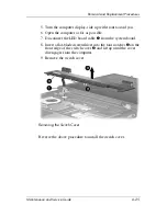
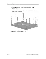
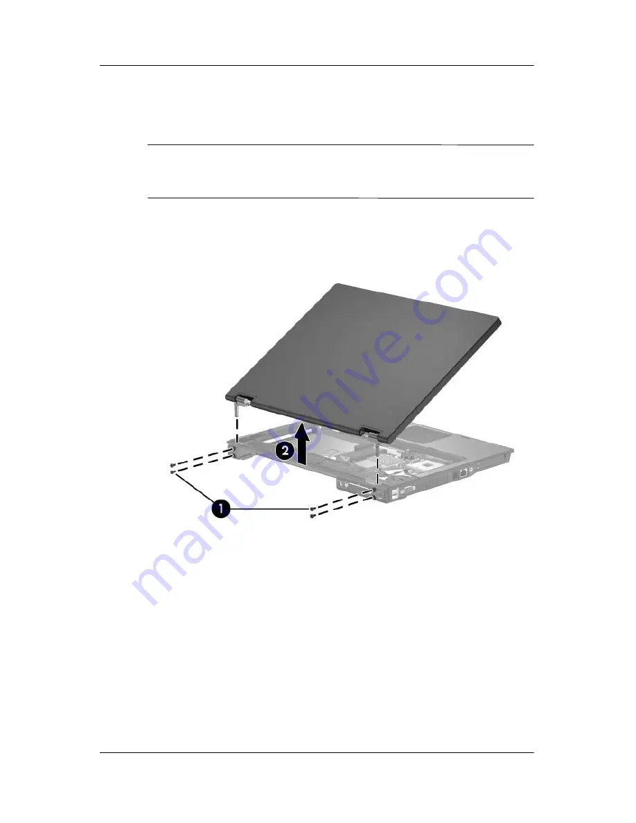
8. Swing the display assembly into a partially closed position.
9. Position the computer with the rear panel toward you.
Ä
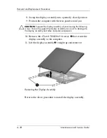
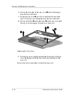
CAUTION:
Support the display assembly when removing the following
screws. Failure to support the display assembly can result in damage to
the display assembly and other computer components.
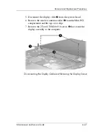
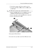
10. Remove the 4 Torx8 T8M2.0×9.0 screws
1
that secure the
display assembly to the computer.
11. Lift the display assembly
2
straight up and remove it.
Removing the Display Assembly
Reverse the above procedure to install the display assembly.
Summary of Contents for Compaq NC6110
Page 74: ...4 4 Maintenance and Service Guide Illustrated Parts Catalog Computer Major Components ...
Page 76: ...4 6 Maintenance and Service Guide Illustrated Parts Catalog Computer Major Components ...
Page 78: ...4 8 Maintenance and Service Guide Illustrated Parts Catalog Computer Major Components ...
Page 80: ...4 10 Maintenance and Service Guide Illustrated Parts Catalog Computer Major Components ...
Page 82: ...4 12 Maintenance and Service Guide Illustrated Parts Catalog Computer Major Components ...
Page 86: ...4 16 Maintenance and Service Guide Illustrated Parts Catalog 4 5 Mass Storage Devices ...