Removal and Replacement Procedures
Maintenance and Service Guide
6–3
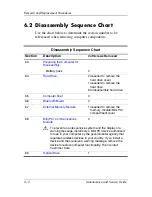
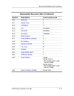
Section
Description
# of Screws Removed
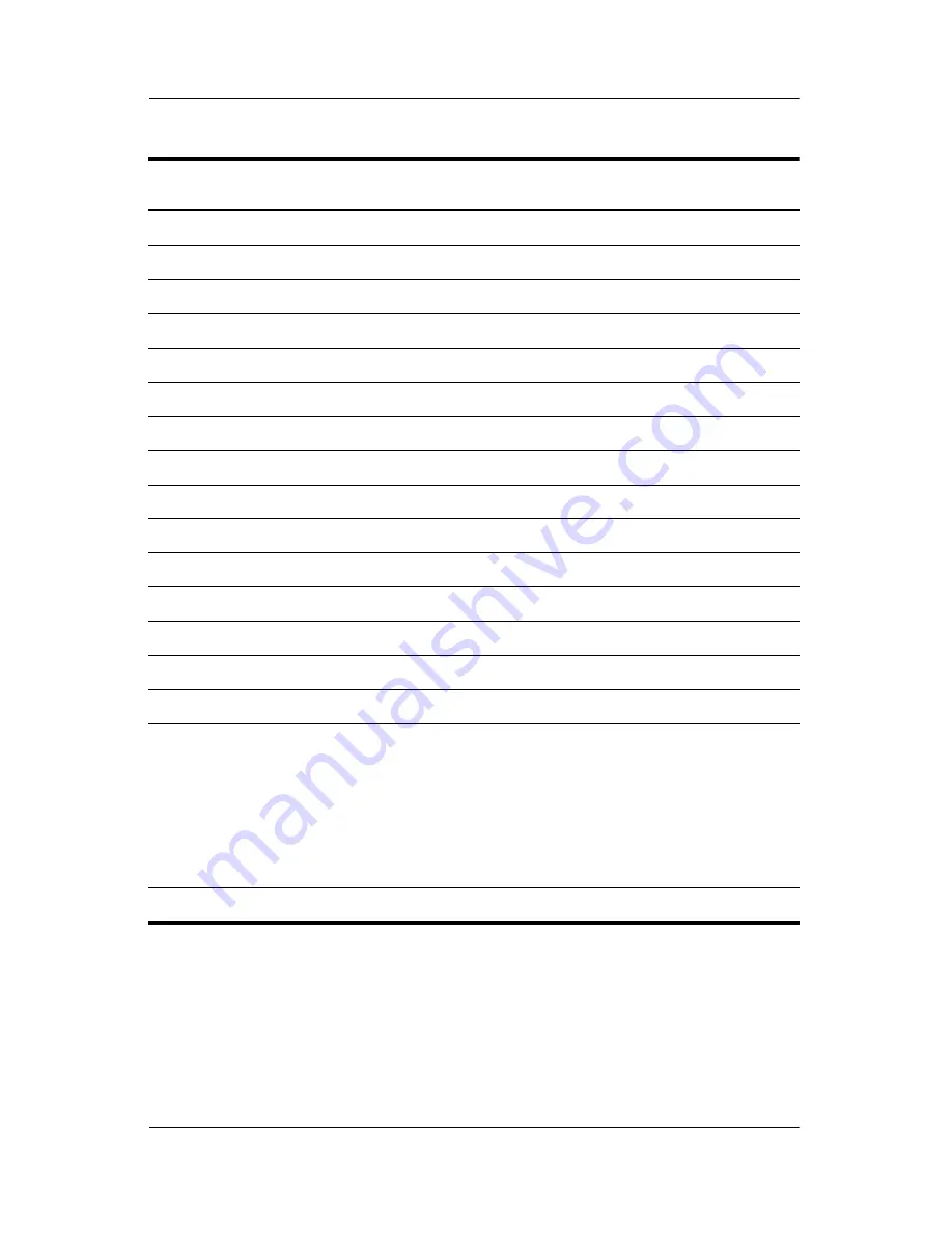
6.10
Keyboard
2
6.11
Switch Cover
2
6.12
LED Board
4
6.13
Fan
2 loosened
6.14
Heat Sink
4 loosened
6.15
Processor
1 loosened
6.16
Modem Board
2
6.17
Internal Memory Module
0
6.18
RTC Battery
0
6.19
Display Assembly
6
6.20
Top Cover
15
6.21
Speaker
4
6.22
Digital Media Board
0
6.23
USB/Audio Board
1
6.24
System Board
1 screw
4 screw locks on
HP Compaq nc6110 and
nc6120 models
2 screw locks on
HP Compaq nx6110 and
nx6120 models
6.25
Serial Connector Module
2 screw locks
Disassembly Sequence Chart
(Continued)
Summary of Contents for Compaq NC6110
Page 74: ...4 4 Maintenance and Service Guide Illustrated Parts Catalog Computer Major Components ...
Page 76: ...4 6 Maintenance and Service Guide Illustrated Parts Catalog Computer Major Components ...
Page 78: ...4 8 Maintenance and Service Guide Illustrated Parts Catalog Computer Major Components ...
Page 80: ...4 10 Maintenance and Service Guide Illustrated Parts Catalog Computer Major Components ...
Page 82: ...4 12 Maintenance and Service Guide Illustrated Parts Catalog Computer Major Components ...
Page 86: ...4 16 Maintenance and Service Guide Illustrated Parts Catalog 4 5 Mass Storage Devices ...