Removal and replacement procedures 56
2.
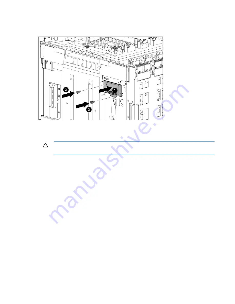
Route the cable between the Insight Display signal pass-thru board pin guide and the screw mounts. Be
careful not to pinch the cable between the Insight Display signal pass-thru board and the screw mount
as shown in the following figure.
3.
Place the Insight Display signal pass-thru board properly over the guide pin and the screw mount and
screw the Insight Display signal pass-thru board to the rear cage assembly.
To verify the enclosure serial number:
CAUTION:
Failure to complete the following procedure might cause inaccurate or incomplete
information to appear in HP SIM and Onboard Administrator.
1.
Using the Insight Display, navigate to the
Enclosure Info
screen.
2.
Verify that the enclosure serial number matches the enclosure serial number on the label on the
enclosure mounting bracket.
o
If the enclosure serial number matches the label, continue to step 7.
o
If the enclosure serial number does not appear or does not match the label, continue to step 3 to
manually update the enclosure identity using the Onboard Administrator CLI.
3.
Use the Onboard Administrator service port address found on the
Enclosure Info
screen to log in to the
Onboard Administrator CLI with the
Administrator
local account password by using one of the
following options:
o
A serial cable attached to the Onboard Administrator serial port
o
An Ethernet CAT5 cable attached to the enclosure service port that is the enclosure link uplink port
4.
Enter the
SET ENCLOSURE PART_NUMBER X
command, where
X
represents the 10-digit enclosure PID
number found on the enclosure front label.
5.
Enter the
SET ENCLOSURE SERIAL_NUMBER Y
command, where
Y
represents the 10-digit serial
number found on the enclosure front label.
6.
Enter the
SET ENCLOSURE PDU_TYPE Z
command, where
Z
represents the number of the appropriate
power configuration:
o
1—Single phase power, U.S.
o
2—Three-phase power, U.S.
o
3—Three-phase power, International


