


Chapter 3
hp Carrier Grade Server bh3710 Power and Cooling Component Overview
DC Power Supplies
3-4
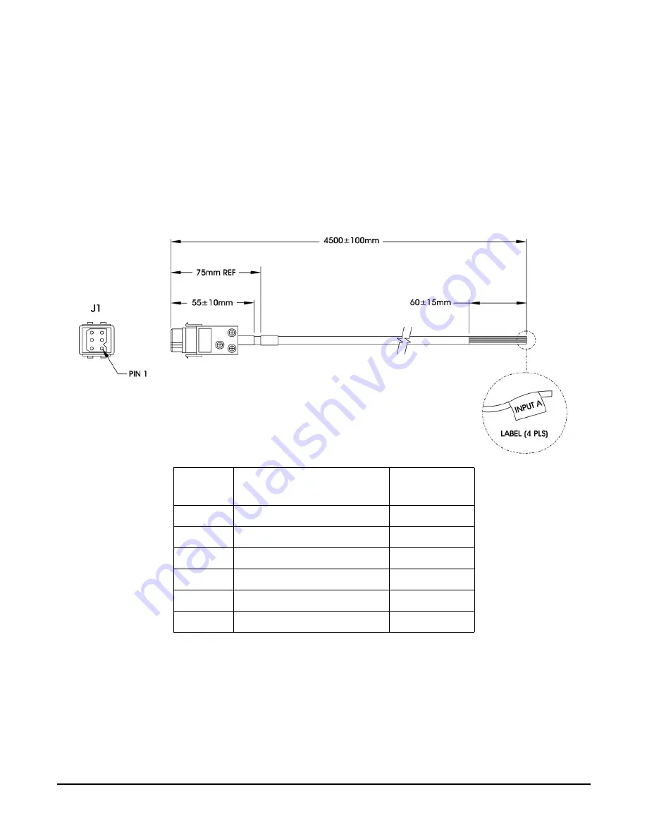
Blade Server Power Supply Connector
DC Power Input Module and Cable Connector Pinout Information
The power supply connector on the input module is a Positronics PLB06. The cable supplied for each power
supply is a 5-wire cable. All 4 wires on each cable must be connected. Two wires (red and black) are connected
to the –48VDC source and the remaining two wires (white and green) are connected to the DC return. All four
wires from the same power cord must be connected to the same power source. Each power supply filter
module may be connected to a different –48VDC source to provide power source redundancy.
Figure 0-4
DC Power Cable
Pin
Number
Function
Color
1
Negative DC Supply (-48vdc)
Red
2
DC Return (0vdc)
White
3
Functional Earth
Not Connected
4
Negative DC Supply (-48vdc)
Black
5
DC Return (0vdc)
Green
6
Functional Earth
Not Connected
Summary of Contents for BH BH3710
Page 6: ...Figures vi ...
Page 8: ...viii ...
Page 10: ...Chapter 1 hp Carrier Grade Server bh3710 Overview Introduction 1 2 ...
Page 52: ...Chapter 7 Specifications for the hp Carrier Grade Server bh3710 Introduction 7 2 ...
Page 54: ...Appendix A LVM Boot Device Hardware Path Change for the hp Carrier Grade Server bh3710 A 2 ...


