Chapter 5
hp Carrier Grade Server bh3710 Server Blade Installation Information
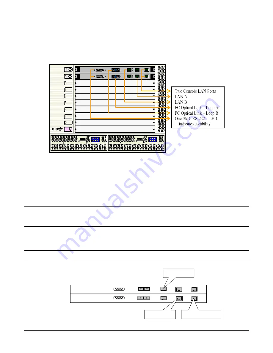
Fibrechannel (FC) and LAN Rear Transition Module (RTM) Blade
5-16
Figure 5-12
bh3710 Chassis (Rear View)
If the Payload LAN and the Management LAN are on separate LAN segments:
Step 1.
In rear slot 9: Plug payload LAN (A) into RJ-45 port A (Center port) on the FC and LAN RTM
blade.
Step 2.
In rear slot 10: Plug the Management LAN into the RJ-45 Management LAN Console (rightmost
port) on the FC and LAN RTM blade.
CAUTION
Either Management LAN port (slot 9 or 10) may be used. However, do not use both
ports on the same switch. Failure to observe this precaution will cause network
malfunction.
Step 3.
In rear slot 10: Plug a Payload LAN (B) into the RJ-45 port B (Left port) on the FC and LAN RTM
blade.
NOTE
Only the LAN A port functions on slot 9. Only the LAN B port functions on slot 10.
S lo t 1 0
S lo t 9
L A N A
M g m t
L A N
S e r i a l
F C L o o p B
S e r i a l F C
L o o p
A
L A N B
L A N B
L A N A
M g m t
L A N
C o n n e c t t o s i t e
P a y l o a d L A N - A
C o n n e c t t o s i t e
P a y l o a d L A N - B
C o n n e c t t o s i t e
M a n a g e m e n t L A N
Summary of Contents for BH BH3710
Page 6: ...Figures vi ...
Page 8: ...viii ...
Page 10: ...Chapter 1 hp Carrier Grade Server bh3710 Overview Introduction 1 2 ...
Page 52: ...Chapter 7 Specifications for the hp Carrier Grade Server bh3710 Introduction 7 2 ...
Page 54: ...Appendix A LVM Boot Device Hardware Path Change for the hp Carrier Grade Server bh3710 A 2 ...


