Step5
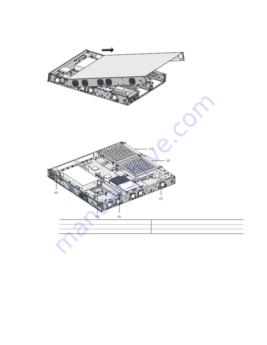
Lift the end of the chassis cover and then
the chassis, as shown below.
Figure 6-4
Remove the chassis cover
Interior Structure
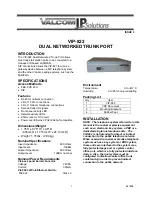
With the chassis cover removed, you can see the interior components of the
Figure 6-5
Interior stru
(1) Slot 1
(3) Fan
(5) Built-in CF card
Installing and Removing Blank Panels
Blank Panel Structure
Installed in Slot 1 or Slot 2 of the
entering the router chassis.
Lift the end of the chassis cover and then pull the chassis cover away from the bottom part of
the chassis, as shown below.
Remove the chassis cover
With the chassis cover removed, you can see the interior components of the A6602
Interior structure of the A6602
(2) Slot 2
(4) Memory slot
(6) Power supply
Installing and Removing Blank Panels
Installed in Slot 1 or Slot 2 of the A6602 rear panel, a blank panel can prevent dust f
pull the chassis cover away from the bottom part of
A6602 router.
rear panel, a blank panel can prevent dust from


