background image

Connecting the RPS DC Power Cable

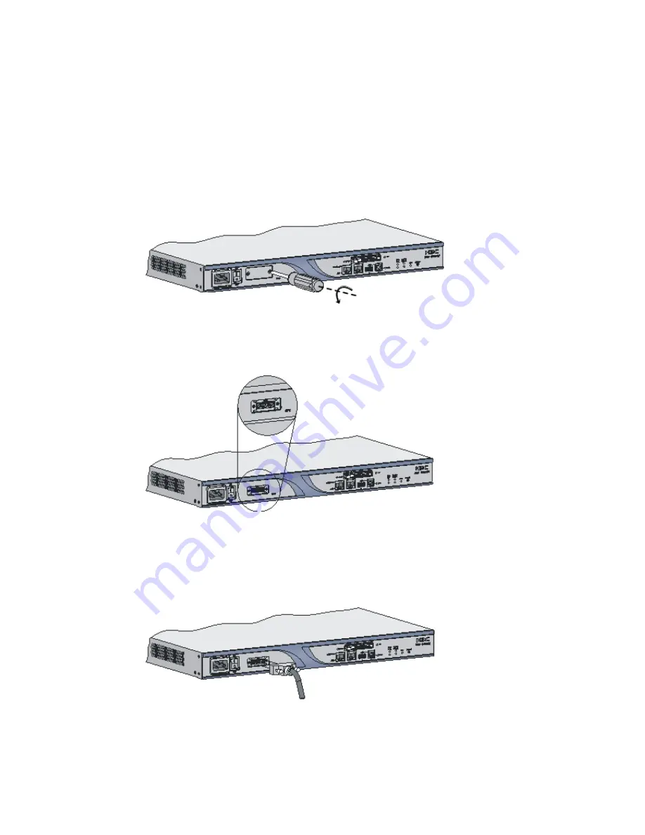
Follow these steps to connect the RPS DC power cable:

Step1

Make sure that the power switch on the router and the RPS input power switch

are both off.

Step2

Rip off the adhesive tape from the RPS socket.

Step3

Loosen the screws on the RPS blank panel with a Phillips screw.

Figure 3-13

Loosen the screws on the RPS blank panel

Step4

Shake the blank panel slightly and then take it off. Now, you can see the RPS

socket.

Figure 3-14

RPS socket

Step5

Plug the RPS power cable into the RPS socket on the router.

Step6

Turn the screws on the RPS connector clockwise to make the connector

plugged in completely, and then fasten the two strain-relief screws on the RPS
connector.

Figure 3-15

Connect the RPS DC power cable to the router

Step7

Connect the other end of the RPS cable to the RPS DC output socket.

Summary of Contents for A6602

Page 1: ...HP A6602 Router Installation Manual ...

Page 2: ... A6602 including device startup power on and initialization of system files and so on 5 Maintaining Software Introduces how to maintain the software of the HP A6602 including upgrading the software and updating the configuration files 6 Maintaining Hardware Introduces how to maintain the hardware of the HP A6602 7 Troubleshooting Describes some problems that may occur during installation and start...

Page 3: ...K Window names menu items data table and field names are inside square brackets For example pop up the New User window Multi level menus are separated by forward slashes For example File Create Folder Symbols Convention Description Means reader be extremely careful Improper operation may cause bodily injury Means reader be careful Improper operation may cause data loss or damage to equipment Means...

Page 4: ...anual introduces all kinds of interface modules that SR6600 routers support the means of connection the interface cables and the interface module purchase guide Low End and Mid Range Series Routers Cable Manual This manual introduces all cable pinouts available with low end and mid range series routers Environmental Protection This product has been designed to comply with the requirements on envir...

Page 5: ...ements of enterprise networks can serve as not only a gateway connecting an enterprise network to a WAN MAN but also a service gateway for example VPN gateway NAT gateway or IPSec gateway in an enterprise network In addition the A6602 can work together with other HP network devices to provide full network solutions for governments and departments in electric power finance tax public security railw...

Page 6: ...thernet interface LED SFP3 5 1000 Mbps optical Ethernet interface LED SFP2 6 1000 Mbps optical Ethernet interface LED SFP1 7 1000 Mbps optical Ethernet interface LED SFP0 8 10 100 1000 Mbps electrical Ethernet interface 3 9 1000 Mbps optical Ethernet interface 3 10 HIM MIM slot 1 12 1000 Mbps optical Ethernet interface 2 13 10 100 1000 Mbps electrical Ethernet interface 2 14 1000 Mbps optical Ethe...

Page 7: ...x Four optical Ethernet interfaces SFP 0 to SFP 3 1000 Mbps full duplex CF card slot 1 The optional CF cards supported by the A6602 are available in three sizes 256 MB 512 MB 1 GB Interface module slots 2 HIM MIM intermixing is supported Two HIMs or two MIMs can be inserted at the same time An electrical Ethernet interface and its corresponding optical Ethernet interface form a Combo interface The...

Page 8: ...732 1GHz multi core microprocessor as its data forwarding and service processing engine Flash The Flash size is 4 MB of which 1 MB is used for storing the boot file the BootWare program and the remaining space for backing up the BootWare program and storing important system parameters Memory module The memory module is used for storing the data during system operation and caching the data during d...

Page 9: ...optional CF cards supported by the A6602 are available in three sizes HP only The device may be incompatible with other CF cards 2 CF card slot 3 CF card LED CF For the description of the CF card LED see Table 1 7 on page 1 6 swappable When the router is performing a file read or write operation on the CF card the CF card LED is blinking do not eject the CF card Otherwise the file sy on the CF car...

Page 10: ... The system is accessing the CF card Do not remove the card in this state Off No host is connected to the USB interface On A host is connected to the USB interface You can unplug the USB cable in this state Blinking Data is being transmitted or received Do not unplug the USB cable in this state 1 10 100 1000 Mbps electrical Ethernet interface LED GE0 2 10 100 1000 Mbps electrical Ethernet interfac...

Page 11: ...perating in the device mode CF card slot 1 The optional CF cards supported by the A6602 are available in three sizes 256 MB 512 MB 1 GB Combo interfaces 4 Four electrical Ethernet interfaces GE0 to GE3 Four optical Ethernet interfaces SFP0 to SFP3 For a Combo interface the default operating interface is the optical Ethernet interface For a Combo interface you can use either the electrical Ethernet...

Page 12: ... cable is connected to the console port on the router and the DB 9 female connector at the other end to the serial port on a configuration terminal illustrates the console cable Console cable connector pinouts Signal direction DB 9 pin 8 6 2 1 5 3 4 7 For the connection of the console cable refer to Connecting the Console Cable in Chapter 3 232 asynchronous serial interface used for remote configu...

Page 13: ...cations for the AUX port Technical specifications for the AUX port Specification RJ 45 RS 232 9600 bps to 115200 bps 9600 bps default Used to connect the serial port of a remote PC through a pair of modems to establish a dial up connection with the PC core shielded cable At one end of the cable is an RJ which is connected to the AUX port on the router At the other end are a DB 9 male connector 25 ...

Page 14: ...e The optical Ethernet interface LEDs are in the middle of the four Combo interfaces and use separate LEDs to indicate the status of the corresponding SFP interfaces Figure 1 8 Combo interfaces on the rear panel 1 10 100 1000 Mbps electrical Ethernet interface GE1 2 1000 Mbps optical Ethernet interface SFP1 3 10 100 1000 Mbps electrical Ethernet interface GE3 4 1000 Mbps optical Ethernet interface...

Page 15: ...nterface supports automatic MDI MDI X in both the forced mode and the auto negotiation mode namely it supports both straight through and crossover cables Technical specifications for optical Ethernet interfaces Table 1 16 Technical specifications for 1000 Mbps optical Ethernet interfaces Item Specification Connector SFP LC Compliant standard 802 3 802 3u and 802 3ab Optical transmit power Type Sho...

Page 16: ...ble passive components in optical fiber communication stems Their application enables the removable connection between optical channels which makes the optical system debugging and maintenance more convenient and the transit dispatching of the system more flexible Some optical fiber connector types are as follows LC square optical fiber connector of the push pull snap in type SC standard optical f...

Page 17: ...rown 7 8 Brown 8 Table 1 18 Crossover cable pinouts RJ 45 pin Signal direction Category 5 twisted pair Signal direction RJ 45 pin 1 Tx White Orange 3 2 Tx Orange 6 3 Rx White Green 1 4 Blue 4 5 White Blue 5 6 Rx Green 2 7 White Brown 7 8 Brown 8 You can refer to the table above when distinguishing between or preparing these two types of Ethernet cables When preparing Ethernet cables please follow ...

Page 18: ... interface 0 2 USB interface 1 3 USB interface 1 LED USB0 USB interface 0 on the A6602 is a USB 1 1 compliant type A interface USB interface 0 can be connected to an external USB storage device to expand the router s space for storing files and logs and facilitate file transfer Insert and remove a USB storage device correctly Otherwise the software hardware and file system of the USB storage devic...

Page 19: ... and MIMs refer to Chapter 6 Maintaining Hardware Hot swapping a module refers to first using the remove slot number command to stop the module and then pulling it out manually or inserting the module into its slot without powering off the device RESET Button To reset the router you can press the RESET button The SYS LED goes off when the router is reset flashes fast at 8 Hz when it is booting and...

Page 20: ... RPS can provide power supply to maintain the normal system operation for a short period when the system power supply fails The RPS uses a control pin to control its output status When the system power supply fails it sends a LOW signal to the control pin of the RPS Upon receiving the LOW signal the RPS switches to the output status within 10 ms and starts to supply power to the router The A6602 s...

Page 21: ...kes and other interferences and minimize impact on the router The A6602 supports three types of signal lightning arresters Voltage limiting protection signal lightning arrester maximum discharge current 2 5KA protection voltage 25V SMB 75J SMB 75J 1W 10Mbps Voltage limiting protection signal lightning arrester maximum discharge current 2 5KA protection voltage 25V BNC 75K BNC 75K 10Mbps Voltage li...

Page 22: ...ly lowers the router s reliability and shortens the service life Table 2 1 lists the requirements on temperature and humidity for the A6602 Table 2 1 Temperature and humidity requirements in the equipment room Temperature Relative humidity 0 C to 45 C 32 F to 113 F 10 to 95 noncondensing Cleanness Requirements Concentration limit of dust Dust is harmful to the safe operation of the router Dust on ...

Page 23: ... m 3 SO2 0 2 H2S 0 006 NH3 0 05 Cl2 0 01 Ventilation Requirements The fans of the A6602 draw air in through the inlet vents on the left and out through the exhaust vents on the right Figure 2 1 Ventilation method for the A6602 Make sure that There is a minimum clearance of 10 cm 3 9 in around the inlet vents and exhaust vents for heat dissipation of the router chassis A ventilation system is avail...

Page 24: ...tively Wear an ESD preventive wrist strap when touching a circuit board or optical interface module Place the removed memory module CF card or HIM MIM on an antistatic workbench with the face upward or put it into an antistatic bag Touch only the edges instead of electronic components when observing or moving a removed memory module CF card or HIM MIM Connection of the ESD preventive wrist strap F...

Page 25: ...necessary Lightning Protection Although many measures have been taken to protect the A6602 from lightning if the lightning intensity exceeds a certain range damage to the router may still happen To protect the router from lightning better you are recommended to do as follows Ensure the PGND cable of the chassis is well grounded Ensure the grounding terminal of the AC power socket is well grounded ...

Page 26: ...ns Installation and removal of the unit and its accessories must be carried out by qualified personnel You must read all of the Safety Instructions supplied with your device before installation and operation Installation und Ausbau der Anlage und ihrer Zubehörteile müssen von qualifiziertem Personal realisiert werden Sie müssen vor der Installation oder Bedienung allen beiliegenden Sicherheitshinw...

Page 27: ...allation Tools Meters and Devices Installation Accessories Supplied with the Router AC power cord Console cable PGND cable Front and back rack mounting ears User supplied tools Phillips screwdrivers P1 100 mm P2 150 mm and P3 250 mm Straight screwdriver P4 75 mm Screws with various specifications Various meters and devices such as hub configuration terminal optional modules and multimeter Optional...

Page 28: ...hen necessary Lightning protection The PGND cable of the chassis is well grounded The grounding terminal of the AC power socket is well grounded A port lightning arrester is installed Optional A power lightning arrester is installed Optional A signal lightning arrester is installed at the input end of an external signal cable Optional Electricity safety Equip an uninterrupted power supply UPS In c...

Page 29: ...the Specified Position You can install the router on a workbench or in a rack Installing the Router Before installing the router make sure that You have read through Chapter 2 Preparing for Installation Make sure all the requirements mentioned in Chapter 2 Preparing for Installation Flowchart Installation flowchart for the A6602 Installing the Router to the Specified Position You can install the r...

Page 30: ... feet of the router See Table 3 1 for the dimensions of the router Dimensions of the A6602 Item Description Dimensions without feet and mounting brackets H 44 442 460 mm 1 73 17 4 18 1 in The workbench is steady and well grounded The workbench is solid enough to support the weight of the router and installation There is a minimum clearance of 10 cm 3 9 in around the router for heat on of the route...

Page 31: ...g brackets fix two screws on the upper central part of the left and right sides of the router so that the router can be fixed on the rear mounting brackets Figure 3 4 Install a screw on the upper central part of each side of the router Step3 Put the router on the rack and fix it with the left and right rear mounting brackets Figure 3 5 Install the router in the rack 1 Rack 2 Screw attached to the ...

Page 32: ...D Cable The correct connection of the protection ground PGND cable on the router chassis is an essential safeguard against the lightning strokes and EMI You need to correctly connect the PGND cable when installing or using the router The AC power input end of the A6602 is equipped with a noise filter The neutral ground of the power input end is directly connected to the chassis and is called PGND ...

Page 33: ...D cable Remove the grounding screw from the router chassis Put the OT terminal of the supplied PGND cable on the grounding screw Fasten the grounding screw into the grounding screw hole with a screwdriver Connect the other end of the PGND cable to the ground Generally the cabinets installed in equipment rooms are equipped with a grounding bar If a grounding bar is available you can connect the PGN...

Page 34: ...discharge current 8 20μs waveform 5 kA output voltage 10 700μs waveform core core 40 V core ground 600 V Tools Phillips or flathead screwdriver Multimeter Diagonal pliers Installation Procedure Follow these steps to install a port lightning arrester Step1 Use a double faced adhesive tape to stick the port lightning arrester to the router The port lightning arrester should be as close to the ground...

Page 35: ... external cable while the OUT end shou connected to the Ethernet port of the router The port lightning arrester is not well grounded Make sure that the grounding cable of the port lightning arrester should be as short as possible and be well connected to the grounding screw of the router You need to check with a multimeter after The installed port lightning arresters are not sufficient When more t...

Page 36: ...n LED is ON and the red LED is OFF the lightning protection can function normally Pay attention and clear the alarm if the red LED is ON You should correctly tell whether the grounding cable is not well connected or the live and zero wires are connected reversely When the red LED is ON use a multimeter to examin polarity at the multi purpose socket of the power lightning arrester If the live and z...

Page 37: ...m discharge current 2 5KA protection voltage 25V SMB 75J SMB 75J 1W 10Mbps Voltage limiting protection signal lightning arrester maximum discharge current 2 5KA protection voltage 25V BNC 75K BNC 75K 10Mbps Voltage limiting protection signal lightning arrester U port maximum discharge current 3KA common mode 400V differential mode 170V RJ11 The signal lightning arrester should be grounded as near ...

Page 38: ...dure Follow these steps to connect the AC power cord Step1 Make sure that the PGND terminal is securely connected to the ground Step2 Move the power switch to the OFF position Step3 Move the bail latch upward Step4 Connect one end of the supplied AC power cord to the power socket on the router and the other end to the power source Step5 Move the bail latch downward to hold the power cord in positi...

Page 39: ... 13 Loosen the screws on the RPS blank panel Step4 Shake the blank panel slightly and then take it off Now you can see the RPS socket Figure 3 14 RPS socket Step5 Plug the RPS power cable into the RPS socket on the router Step6 Turn the screws on the RPS connector clockwise to make the connector plugged in completely and then fasten the two strain relief screws on the RPS connector Figure 3 15 Con...

Page 40: ...eps to connect the console cable Step1 Select a configuration terminal The configuration terminal can be a standard ASCII terminal with an RS232 serial port or a common PC Step2 Connect the console cable Disconnect the power supply to the router Connect the RJ 45 connector of the console cable to the console port on the router and the DB 9 female connector to the serial port on the configuration t...

Page 41: ...45 connector to the console port on the router Connecting the AUX Port to a Modem The AUX port is usually used for remote configuration or dial backup In this case you need to connect the local modem to the remote modem through PSTN and then to the remote device Follow these steps to connect the AUX port with an AUX cable Step1 Plug the RJ 45 connector of an AUX cable into the AUX port on the rout...

Page 42: ...traight through cable or crossover cable to connect the port Step2 Check the status of the LED of the fixed electrical Ethernet port after power on For the status of the LED see Table 3 4 Table 3 4 Status of the LED LED Color Status GE0 to GE3 yellow green Off No link is present Solid green A 1000 Mbps link is present Flashing green Data is being transmitted received at 1000 Mbps Solid yellow A 10...

Page 43: ...t an SFP module Step3 Identify the Rx and Tx ports on the SFP module Plug the LC connector at one end of one fiber cable into the Rx port of the router and the LC connector at the other end into the Tx port of the peer device Plug the LC connector at one end of another fiber cable into the Tx port of the router and the LC connector at the other end to the Rx port of the peer device ...

Page 44: ... is present Flashing green Data is being transmitted received at a rate of 1000 Mbps Solid yellow The SFP module fails to be detected vely bending optical fiber cables with the curvature radius less than Ensure that the Tx and Rx ports of the SFP module are connected correctly faces of optical fiber cables clean stare into an open SFP interface on the interface module because invisible rays may be...

Page 45: ...h is stable enough The power supply matches the requirements of the router The PGND cable of the router is correctly connected The router is correctly connected to the configuration terminal and other devices It is very important to verify the installation because the stability and grounding of the router and the power supply will directly affect the operation of the router ...

Page 46: ...pter 3 Installing the Router Setting the Parameters for the Console Terminal Step1 Create a HyperTerminal connection Select Start Programs Accessories Communications HyperTerminal and enter a connection name in the Connection Description dialog box as shown below Figure 4 1 Create a connection Step2 Select a connection port Select a serial port from the Connect using drop down list in the Connect ...

Page 47: ...meters Set the properties of the serial port in the COM1 Properties dialog box as shown in Figure 4 3 Table 4 1 Set serial port parameters Item Value Bits per second 9600 bps default Data bits 8 Parity None Stop bits 1 Flow control None To use the default settings click Restore Defaults ...

Page 48: ... below Figure 4 4 HyperTerminal window Step5 Set HyperTerminal properties In the HyperTerminal window select File Properties from the menu and select the Settings tab to enter the properties setting dialog box as shown below Select VT100 or Auto detect from the Emulation drop down list and click OK to return to the HyperTerminal window ...

Page 49: ...inal is powered on and the emulation program is properly configured If an external CF card is needed to store applications the CF card is properly installed Before powering on the router locate the position of the power switch for the equipment room where you will operate so that you can switch off the power supply promptly in case of any accident Powering On the Router Turn on the power source Tu...

Page 50: ...t In this state you can remove the USB cable 2 The fans work normally 3 The buzzer beeps at power on 4 The configuration terminal displays information normally You can see the startup window on the local configuration terminal For more information see Startup Process on page 4 5 5 After the power on self test POST the system prompts you to press Enter When the command line prompt appears the route...

Page 51: ...plication file cfa0 A6602 bin The main application file is self decompressing Done System is starting User interface con0 is available Press ENTER to get started Press Enter The screen will display HP This prompt indicates that the router has entered user view and is ready to configure Configuration Fundamentals In general the configuration steps are as follows Step1 Before configuring the router ...

Page 52: ...g the telnet command Provides online help which is available by entering Provides network diagnostic tools such as Tracert and Ping for quick diagnosis of network connectivity Provides all kinds of detailed debugging information to help diagnose network faults Supports the auto complete function If you enter a conflict free part of a command the command will be interpreted For example you just nee...

Page 53: ...tored in a CF card By default they are written into the built in CF card before delivery If you have uploaded all the three types of application files into the built in CF card the system will boot using these three files in order For more information about application files refer to Maintaining Application and Configuration Files on page 5 27 The following gives the default names and types of the...

Page 54: ...stem When saving the current configuration you can specify to save it to the main configuration file the backup configuration file or a configuration file with the attribute denoted by N A namely a configuration file without a specific attribute assigned to it When deleting a configuration file you can specify to delete the main or backup configuration file For a configuration file with both M and...

Page 55: ...ation file make sure to secure the power supply during this process any power failure during this process will cause application update to fail and will damage the existing application file In this case if there was only one application file for booting the system the device will be unable to start normally When updating the basic BootWare section make sure to secure power supply during this proce...

Page 56: ... Extend BootWare is self Done HP A6602 BootWare Version 1 18 BootWare and Comware updating flow When the router is powered on it first initializes the memory After the initialization the system runs the extended segment of the BootWare and the following information is displayed on the Booting Normal Extend BootWare The Extend BootWare is self decompressing BootWare Version 1 18 When the router is ...

Page 57: ...s if you want to enter the extended BootWare menu you need to reboot the router The extended BootWare menu is referred to as the main menu in this manual unless otherwise specified Press Ctrl B when Press Ctrl B to enter extended boot menu appears and the system prompts Please input BootWare password After you type the correct BootWare password the system will display The initial BootWare password...

Page 58: ...time This option is generally used when you lose the password 7 BootWare Operation Menu BootWare operation sub menu For detailed information refer to BootWare Operation Sub menu on page 5 9 8 Clear Super Password Clear the super password The super password is used in user level switching No super password is set by default This setting is valid for the first reboot of the router only The super pas...

Page 59: ...ters 0 Exit To Main Menu Return to the main menu Ethernet Sub menu Select 3 from the main menu to enter the Ethernet sub menu where you can update application files and the BootWare program using FTP TFTP The system displays Enter Ethernet SubMenu Note the operating device is cfa0 1 Download Application Program To SDRAM And Run 2 Update Main Application File 3 Update Backup Application File 4 Upda...

Page 60: ...e Table 5 4 File control sub menu Menu item Description 1 Display All File s Display all files 2 Set Application File type Set the application file type 3 Set Configuration File type Set the configuration file type 4 Delete File Delete a file 0 Exit To Main Menu Return to the main menu BootWare Operation Sub menu Select 7 from the main menu to enter the BootWare operation sub menu BootWare Operati...

Page 61: ...nd BootWare Through a Serial Interface Introduction to Xmodem Use Xmodem when updating an application and BootWare through a serial interface Xmodem is a file transfer protocol that is widely used due to its simplicity and high performance Xmodem transfers files through a serial interface It supports two types of data packets 128 bytes and 1 KB two check methods checksum and CRC and error packet r...

Page 62: ...0 3 38400 4 57600 5 115200 0 Exit Enter your Choice 0 5 Select a proper baud rate For example select 5 for a baud rate of 115200 bps and the system displays the following information Baudrate has been changed to 115200 bps Please change the terminal s baudrate to 115200 bps press ENTER when ready At this time the baud rate of the serial interface of the router is modified to 115200 bps while that ...

Page 63: ...ts Updating an Application The application updating through a serial interface is implemented on the serial sub menu Select 2 from the main menu to enter the serial sub menu For detailed description on this sub menu refer to Serial Sub menu on page 5 7 The following example shows how to update the main application file main bin To improve the updating speed you can modify the serial port baud rate...

Page 64: ...ox After the file is downloaded the following information appears on the terminal interface 11673728 bytes downloaded The system prompts you to enter the name of application file to be downloaded to the current from that of any existing file on the storage medium the application file will be saved as this file name for example Input the File Name main bin Updating File cfa0 main bin Done After tha...

Page 65: ...herefore you are recommended to update the application through an Ethernet interface Enter the main menu refer to Main Menu on page 5 5 Select 7 to enter the BootWare menu where you can perform all BootWare operations For detailed description BootWare Operation Sub menu on page 5 9 The following example shows how to update the entire BootWare To update the entire BootWare you need to first update ...

Page 66: ...e update downloaded Updating Basic BootWare Y N the system displays Updating Extend BootWare Y N The system stops updating the basic segment and asks you whether to update the extended the system updates the basic segment Updating Basic BootWare Done Updating Extend BootWare Y N Y The basic segment is successfully updated and the system asks you whether to update the the system stops updating the ...

Page 67: ...n file on the router to from the file server There are two approaches to updating application files using TFTP Updating an Application Using TFTP on the BootWare Menu Set up a TFTP update environment Set up a TFTP update environment Router serves as the TFTP client and PC serves as the TFTP server Connect Ethernet interface GigabitEthernet 0 0 on the router to the PC using a crossover Ethernet cab...

Page 68: ...Target File Name Name of the target file after the file is downloaded to the router The extension of the target file needs to be same as that of the downloaded file Note that The first main bin is the file name automatically remembered by the system at the last update The second main bin is the source file name set by the user An application file name including the extension such as bin cannot exc...

Page 69: ...re for setting up an updating environment refer to Updating an Application Using TFTP on the BootWare Menu on page 5 16 Run the terminal emulation program on the PC and then configure the IP addresses of the client and sever to be on the same network segment Ensure the connectivity between the router and the PC In the example the IP address of the GigabitEthernet 0 0 is 192 168 80 10 and that of P...

Page 70: ...he file name already exists on the router the system prompts whether to overwrite the file on the router You need to enter Y or N for confirmation For details about the tftp command refer to HP SR6600 Routers User Manual You can update a configuration file in the way you update an application file A configuration file can be modified by a text editor You can modify a configuration file and then do...

Page 71: ... this approach the router can serve as the FTP client only At the CLI In this approach the router can serve as the FTP server or the FTP client Updating an Application Using FTP on the BootWare Menu Set up an FTP update environment Set up an FTP update environment The router serves as the FTP client and the PC serves as the FTP server Connect the Ethernet interface GigabitEthernet 0 0 on the route...

Page 72: ...er logged in You have logged into the FTP server successfully 5 Update an application file Using FTP you can download an application file from the server to the router and overwrite the original main application file to implement the application update The updated application file takes effect when the router reboots Download file main bin from the PC to the router and save it as main bin ftp get ...

Page 73: ...ion file Table 5 10 Description on the information displayed when you update and back up an application file on the router Display information Description ftp get main bin main bin Download the file used for updating cfa0 main bin has been existing Overwrite it Y N y The system prompts whether to overwrite the existing file FTP 11673608 byte s received in 120 735 second s 96 00K byte s sec Downloa...

Page 74: ...er and client to be on the same network segment In this example the IP address of interface GigabitEthernet 0 0 is 192 168 80 10 and that of the PC is command to check whether the connection is successful You can update the applications of the A6602 through GigabitEthernet 0 0 only Add FTP username and password type ftp guest password simple 123456 authorization attribute level 3 Description on th...

Page 75: ...er 192 168 80 10 none guest 331 Password required for guest Password 230 User logged in Table 5 12 Description on the display information of enabling FTP client Display information Description C Documents and Settings Administrator ftp Enable the FTP client program on the PC ftp open 192 168 80 10 In FTP client view log into the IPv4 FTP server User 192 168 80 10 none Input the username configured...

Page 76: ...n application file if the file name already exists on the server the system overwrites the file on the server directly without any prompt For details about the get command refer to HP SR6600 Routers User Manual You can back up a configuration file using the same method as backing up an application file Table 5 13 Description on the display information of enabling FTP server Display information Des...

Page 77: ...0 FAT16 Table 5 14 Description on the display information of the dir command Display information Description Directory of cfa0 Name of the current directory 506336 KB total 476704 KB free Used space of the CF card available space File system type of cfa0 File system type of the CF card For details about the dir command refer to HP SR6600 Routers User Manual Setting the Application File Attributes ...

Page 78: ...and will set the boot file Continue Y N y The specified file will be used as the main boot file at the next reboot Now the attribute of the file main bin has changed from B to M B and the file will be used as the main application file at the next boot while the attribute of another existing file main_bak bin has automatically changed from the original M to N A You can verify the changes of the fil...

Page 79: ...iles cfa0 main cfg and or cfa0 backup cfg if any are automatically assigned the M and or B attributes respectively Setting configuration file attributes at the CLI You can use the startup saved configuration cfgfile backup main command to define the configuration file to be used for the next boot and its attribute In this command use cfgfile argument to specify the configuration file name Note tha...

Page 80: ...CURE N A NOT ASSIGNED NO Size B Time Type Name 1 11673608 Nov 15 2007 05 39 50 B cfa0 main bin 2 1227 Nov 11 2007 16 25 52 N A cfa0 startup cfg 3 2294 Nov 11 2007 14 47 32 N A cfa0 startup cfg 4 2094 Nov 11 2007 13 47 34 N A cfa0 startup_bac cfg 0 Exit Enter file No Enter the file number select 4 and the system prompts The file you selected is cfa0 startup_bac cfg Delete it Y N Enter Y If the syst...

Page 81: ...tem will be halted and prompt Wrong password system halt After you enter the correct old password the system prompts you to enter a new password twice Please input new password Please input new password again If the system displays the following information the password is successfully modified Password Set Successfully The BootWare password you entered is displayed in the form of asterisks The Bo...

Page 82: ...red in the storage medium To restore the original configuration you can use the display saved configuration command to display the configuration and then copy and execute the configuration If the password is stored in plain text you can use the display current configuration command to view the password in the current configuration If the password 123456 is set with the set authentication password ...

Page 83: ...stem prompts Will you backup the Basic BootWare Y N Enter Y Begin to backup the Basic BootWare Done At this moment backup for the basic segment is finished The system continues to prompt Will you backup the Extend BootWare Y N Enter Y Begin to backup the Extend BootWare Done At this moment backup for the extended segment is finished Both the basic and extended BootWare segments are backed up to th...

Page 84: ...oid touching any components on the PCB during observation or moving Put the removed module on an antistatic workbench with the PCB side facing upward or place them in antistatic bags 5 Run the corresponding commands before hot swapping the following boards Use the remove slot slotnumber subslot subslot number command before hot swapping a HIM MIM If you have run this command but do not want to rem...

Page 85: ...on the rear panel while keeping the ground cable connected and remove the fastening screws on both sides and the top of the router Remove screws at both sides and on the top of the router insert two flat blade screwdrivers into the key holes on both sides of the chassis and gently rotate the screwdrivers until the top and bottom sections separate Insert a screwdriver into one key hole and rotate t...

Page 86: ... entering the router chassis Lift the end of the chassis cover and then pull the chassis cover away from the bottom part of the chassis as shown below Remove the chassis cover With the chassis cover removed you can see the interior components of the A6602 Interior structure of the A6602 2 Slot 2 4 Memory slot 6 Power supply Installing and Removing Blank Panels Installed in Slot 1 or Slot 2 of the ...

Page 87: ...nk panel 3 Back view of a blank panel 4 EMI gasket Removing a Blank Panel Follow these steps to remove a blank panel Position the router so that the rear panel of the router faces you Select the slot where you will install a HIM or MIM In the case that you need to install a HIM remove both the upper and lower blank panels in In the case that you need to install a MIM remove the lower blank panel i...

Page 88: ...ved install two blank panels e that a MIM is removed install one blank panel Tighten the fastening screws with a Phillips screwdriver Install a blank panel Installing and Removing a HIM Follow these steps to install a HIM sition the router so that the rear panel faces you Remove the two blank panels from the slot where you will install the HIM For the removal Removing a Blank Panel in Page 6 5 Gen...

Page 89: ...ails Follow these steps to remove a HIM hat the rear panel of the router faces you Loosen the captive screws on the HIM with a flat blade screwdriver Loosen the captive screws on a HIM Grasping the two ejector levers with both hands pivot the ejector levers outward Remove the HIM Before pulling a HIM out of a slot loosen the two captive screws Otherwise the panel of the HIM may be seriously deform...

Page 90: ...ed if the LED is on the MIM is correctly installed and operates normally if the LED is off the MIM failed the self test Removing a MIM Follow these steps to remove a MIM Step1 Position the router so that the rear panel of the router faces you Step2 Loosen the captive screws on the MIM with a flat blade screwdriver Figure 6 15 Loosen the captive screws on a MIM Step3 Pull the MIM out of the slot al...

Page 91: ...ng a CF Card Follow these steps to install a CF card Make sure that the CF card LED is not blinking before proceeding with the next step Press the CF card eject button in and make sure it does not project from the panel Insert the CF card into the slot and push it all the way in until it is firmly seated Insert the CF card into the slot If the application program for booting the router is stored i...

Page 92: ...ule is damaged Eject the CF card Press the eject button again to eject the CF card part way out of the slot and then pull the card Press the eject button to eject the CF card To avoid hardware damage do not remove the CF card when the router is booting or the CF the CF card place it into an antistatic bag Replacing a Memory Module When to Replace a Memory Module Memory modules are removable compon...

Page 93: ...ment flowchart Figure 6 20 Memory module replacement flowchart les provided by Hangzhou HP Technologies Co Ltd only Otherwise the router may be unable to operate normally For the specific specifications for memory modules supported by the A6602 1 4 1 Processor and Storages in Chapter 1 Router Overview Flow of Replacing a Memory Module shows the memory module replacement flowchart Memory module rep...

Page 94: ...d from the memory module slot Step3 Remove the memory module by holding its non Memory Module Structure Structure of a memory module used in the A6602 2 Polarization notch Memory module slot 2 Memory module slot Removing a Memory Module Follow these steps to remove a memory module all power supplies to the router are disconnected Pull the release latches away from the memory module at both ends so...

Page 95: ...are disconnected Step2 Align the polarization notch of the memory module with the key in the memory module slot Step3 Position the memory module so that it is perpendicular to the main board and insert the memory module into the memory module slot Step4 Carefully and firmly press the memory module at both ends until you hear a click This indicates the memory module is seated in the memory module s...

Page 96: ...mptom The router cannot be powered on The power LED on the front panel is off Solution Follow these steps to troubleshoot the power system Turn off the power switch Remove the chassis cover Check whether the power cord is properly and firmly connected Check whether the power cord is not damaged If the cause cannot be located in the steps above and the problem persists contact your local sales agen...

Page 97: ...follows 9600 bits per second 8 data bits 1 stop bit no flow control and VT100 for terminal emulation type The configuration cable is not in good condition Illegible Characters on the Terminal Screen Symptom After the router is powered on the configuration terminal displays illegible characters Solution If the Data bits field is set to 5 or 6 in the emulation program illegible characters appear on ...

Page 98: ... If you have lost the BootWare password user password or super password refer to Dealing With Password Loss in Chapter 5 Maintaining Software Troubleshooting the Cooling System Symptom The temperature inside the router exceeds 45 C 113 F Solution Check whether the fans are running normally Check whether the working environment of the router is well ventilated If the temperature inside the router e...

Page 99: ...es and Connections Symptom After an HIM MIM is installed and the router is powered on the LEDs on the HIM MIM panel indicate abnormal operation Solution Check that The HIM MIM cable was correctly selected The HIM MIM cable is correctly connected The interface has been correctly configured and is working normally use the display command ...

Reviews: