Stepping
Through
the
Measurement
There
are
four
basic
steps
in
performing
a
stimulus-response
measurement,
whether
it
be
a
transmission
or
reection
measurement:
set
up
the
receiver
settings
,
calibrate
,
normalize
,
and
measure
.
1.
If
necessary
,
perform
the
self-calibration
routine
for
the
tracking
generator
described
in
\P
erforming
the
Tracking
Generator
Self-Calibration
Routine
"
in
Chapter
2.
2.
T
o
measure
the
rejection
of
a
bandpass
lter
,
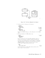
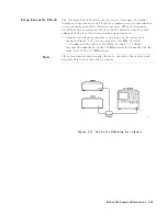
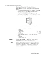
connect
the
equipment
as
shown
in
Figure
7-2 .
This
example
uses
a
bandpass
lter
with
a
center
frequency
of
321.4
MHz
as
the
DUT
.
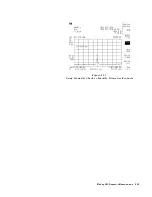
Figure
7-2.
Transmission
Measurement
T
est
Setup
3.
Set
the
receiver
to
a
known
state
by
pressing:
4
PRESET
5
4
FREQUENCY
5
NNNNNNNNNNNNNNNNNNNNNNNNNNNNNNNNNNN
CENTER
FREQ
:
:
:
:
:
:
:
:
:
:
:
:
:
:
:
:
:
:
:
:
:
:
:
:
:
:
:
:
:
:
:
:
:
:
:
:
:
:
:
321.4
4
MHz
5
4
SP
AN
5
:
:
:
:
:
:
:
:
:
:
:
:
:
:
:
:
:
:
:
:
:
:
:
:
:
:
:
:
:
:
:
:
:
:
:
:
:
:
:
:
:
:
:
:
:
:
:
:
:
:
:
500
4
MHz
5
4
AMPLITUDE
5
:
:
:
:
:
:
:
:
:
:
:
:
:
:
:
:
:
:
:
:
:
:
:
:
:
:
:
:
:
:
:
:
:
:
:
:
:
:
:
:
:
:
:
102
4
+dBV
5
4.
A
ctivate
the
tracking
generator
and
turn
the
power
on
by
pressing:
4
TRK
GEN
5
NNNNNNNNNNNNNNNNNNNNNNNNNNNNNNNNNNNNNNNNNNNN
SRC
PWR
ON
OFF
ON
CA
UTION
Excessive
signal
input
may
damage
the
DUT
.
Do
not
exceed
the
maximum
power
that
the
device
under
test
can
tolerate
.
Note
T
o
reduce
ripples
caused
by
source
return
loss
,
use
10
dB
or
greater
tracking
generator
output
attenuation.
Tracking
generator
output
attenuation
is
normally
a
function
of
the
source
power
selected.
However
,
the
output
attenuation
may
be
controlled
by
using
NNNNNNNNNNNNNNNNNNNNNNNNNNNNNNNNNNNNNNNNNNNNNNNNNN
SRC
ATN
AUTO
MAN
.
Making
Other
Measurements
7-3


