EVA cabinet measures and tolerances
EVA component rack mount brackets are designed to fit cabinets with mounting rails set at depths
from 27.5 inches to 29.6 inches, inside rails to inside rails.
Weights, dimensions and component CG measurements
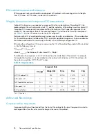
Cabinet CG dimensions are reported as measured from the inside bottom of the cabinet (Z), the
leading edge of the vertical mounting rails (Y), and the centerline of the cabinet mounting space (X).
Component CG measurements are measured from the bottom of the U space the component is to
occupy (Z), the mounting surface of the mounting flanges (Y), and the centerline of the component
(X).
Table 21
lists the CG dimensions for the EVA components.
Determining the CG of a configuration may be necessary for safety considerations. CG considerations
for CG calculations do not include cables, PDU’s and other peripheral components. Some consideration
should be made to allow for some margin of safety when estimating configuration CG.
Estimating the configuration CG requires measuring the CG of the cabinet the product will be installed
in. Use the following formula:
Σ
d
component
W = d
system cg
W
where d
component
= the distance of interest and W = Weight
The distance of a component is its CG’s distance from the inside base of the cabinet. For example,
if a loaded disk enclosure is to be installed into the cabinet with its bottom at 10U, the distance for
the enclosure would be (10*1.75)+2.7 inches.
Table 21 Component data
Component Data
Z (in)
Y (in)
X (in)
Weight (Lb)
U height
1
14.21
25.75
-0.108
233
HP 10K cabinet CG
0
2.625
0
1.4
3
Filler panel , 3U
7.95
2.7
-0.288
74
3
Fully loaded drive enclosure
0
0.875
0
0.47
1
Filler panel, 1U
10.64
2.53
-0.094
120
4
XL Controller Pair
1
1U = 1.75 inches
Airflow and Recirculation
Component Airflow Requirements
Component airflow must be directed from the front of the cabinet to the rear. Components vented to
discharge airflow from the sides must discharge to the rear of the cabinet.
Non-standard rack specifications
98
Summary of Contents for 6400/8400
Page 12: ...12 ...
Page 16: ...About this guide 16 ...
Page 60: ...EVA6400 8400 operation 60 ...
Page 66: ...Customer replaceable units 66 ...
Page 80: ...Error messages 80 ...

