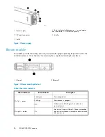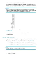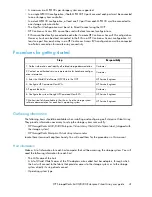
4. Status indicator (solid green on — normal opera-
tion; solid amber — failure or no power)
1. Power supply
5. Handle
2. AC input connector
3. Latch
Figure 12 Power supply
.
Blower module
Fan modules provide the cooling necessary to maintain the proper operating temperature within the
controller enclosure. If one fan fails, the remaining fan is capable of cooling the enclosure.
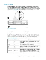
2. Blower 2
1. Blower 1
Figure 13 Blower module pulled out
.
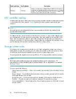
Table 8 Fan status indicators
Description
Fault indicator
Status indicator
Normal operation.
Solid green
On left — green
Maintenance in progress.
Blinking
Amber is on or blinking, or the enclosure is
powered down.
Off
Fan failure. Green will be off. (Green and amber
are not on simultaneously except for a few seconds
after power-up.)
On
On right — amber
EVA6400/8400 hardware
26
Summary of Contents for 6400/8400
Page 12: ...12 ...
Page 16: ...About this guide 16 ...
Page 60: ...EVA6400 8400 operation 60 ...
Page 66: ...Customer replaceable units 66 ...
Page 80: ...Error messages 80 ...


