background image

Canadian notice (avis Canadian)

Class A equipment

This Class A digital apparatus meets all requirements of the Canadian Interference-Causing Equipment
Regulations.

Cet appareil numérique de la classe A respecte toutes les exigences du Règlement sur le matériel
brouilleur du Canada.

Class B equipment

This Class B digital apparatus meets all requirements of the Canadian Interference-Causing Equipment
Regulations.

Cet appareil numérique de la classe B respecte toutes les exigences du Règlement sur le matériel
brouilleur du Canada.

European union notice

Products with the CE Marking comply with both the EMC Directive (2004/108/EC) and the Low
Voltage Directive (2006/95/EC) issued by the Commission of the European Community.

Compliance with these directives implies conformity to the following European Norms (the equivalent
international standards are in parenthesis):

EN55022 (CISPR 22) - Electromagnetic Interference

EN55024 (IEC61000-4-2, 3, 4, 5, 6, 8, 11) - Electromagnetic Immunity

EN61000-3-2 (IEC61000-3-2) - Power Line Harmonics

EN61000-3-3 (IEC61000-3-3) - Power Line Flicker

EN60950 (IEC950) - Product Safety

Notice for France

DECLARATION D'INSTALLATION ET DE MISE EN EXPLOITATION d'un matériel de traitement de
l'information (ATI), classé A en fonction des niveaux de perturbations radioélectriques émis, définis
dans la norme européenne EN 55022 concernant la Compatibilité Electromagnétique.

WEEE Recycling Notices

English notice

Disposal of waste equipment by users in private household in the European Union

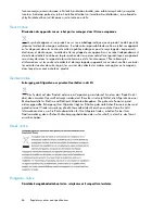
This symbol on the product or on its packaging indicates that this product must not be disposed

of with your other household waste. Instead, it is your responsibility to dispose of your waste equipment
by handing it over to a designated collection point for recycling of waste electrical and electronic
equipment. The separate collection and recycling of your waste equipment at the time of disposal will
help to conserve natural resources and ensure that it is recycled in a manner that protects human
health and the environment. For more information about where you can drop off your waste equipment

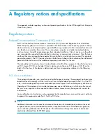
Regulatory notices and specifications

84

Summary of Contents for 6400/8400

Page 1: ...HP StorageWorks 6400 8400 Enterprise Virtual Array user guide Part number 576284 001 Second edition August 2009 ...

Page 2: ...such products and services Nothing herein should be construed as constituting an additional warranty HP shall not be liable for technical or editorial errors or omissions contained herein WARRANTY STATEMENT To obtain a copy of the warranty for this product see the warranty information website Microsoft and Windows are U S registered trademarks of Microsoft Corporation Java is a US trademark of Sun...

Page 3: ...isk drives 20 Disk drive status indicators 21 Disk drive blank 21 Controller enclosures 21 Operator control panel 23 Status indicators 24 Navigation buttons 25 Alphanumeric display 25 Power supplies 25 Blower module 26 Battery module 27 HSV controller cabling 28 Storage system racks 28 Rack configurations 29 Power distribution 29 PDUs 30 PDU 1 31 PDU 2 31 PDMs 31 Rack AC power distribution 32 Rack...

Page 4: ...etting 49 Implicit LUN transition 50 Storage system shutdown and startup 50 Shutting down the storage system 50 Starting the storage system 51 Saving storage system configuration data 52 Adding disk drives to the storage system 53 Creating disk groups 53 Handling fiber optic cables 53 Using the OCP 54 Displaying the OCP menu tree 54 Displaying system information 56 Displaying versions system infor...

Page 5: ... English notice 84 Dutch notice 85 Czechoslovakian notice 85 Estonian notice 85 Finnish notice 85 French notice 86 German notice 86 Greek notice 86 Hungarian notice 86 Italian notice 87 Korean Communication Committee notice 87 Latvian notice 87 Lithuanian notice 87 Polish notice 88 Portuguese notice 88 Slovakian notice 88 Slovenian notice 89 Spanish notice 89 Swedish notice 89 Germany noise declar...

Page 6: ...at a glance 104 Installation requirements 104 Recommended mitigations 104 Supported configurations 104 General configuration components 105 Connecting a single path HBA server to a switch in a fabric zone 105 HP UX configuration 107 Requirements 107 HBA configuration 107 Risks 108 Limitations 108 Windows Server 2003 32 bit configuration 109 Requirements 109 HBA configuration 109 Risks 109 Limitati...

Page 7: ...ration 119 Risks 119 Limitations 119 IBM AIX configuration 120 Requirements 120 HBA configuration 120 Risks 121 Limitations 121 VMware configuration 122 Requirements 122 HBA configuration 122 Risks 122 Limitations 122 Failure scenarios 123 HP UX 123 Windows Server 2003 124 Sun Solaris 124 OpenVMS and Tru64 UNIX 125 NetWare 126 Linux 126 IBM AIX 127 VMware 128 Glossary 129 Index 147 HP StorageWorks...

Page 8: ...onents back view 29 15 60 Hz and 50 Hz wall receptacles 29 16 Dual PDU assembly 31 17 Rack PDM 32 18 Rack AC power distribution 33 19 Single rack configuration floor space requirements 35 20 Raising a leveler foot 35 21 EVA8400 configuration 38 22 EVA6400 configuration 39 23 Location of the World Wide Name labels 43 24 Typical product label 62 25 Typical enclosure certification label 91 26 GUI ter...

Page 9: ...aris configuration 113 35 Tru64 UNIX configuration 114 36 OpenVMS configuration 116 37 NetWare configuration 117 38 Linux 32 bit configuration 118 39 Linux 64 bit configuration 120 40 IBM AIX Configuration 121 41 VMware configuration 123 42 HP StorageWorks 6400 8400 Enterprise Virtual Array user guide 9 ...

Page 10: ...anging failover failback setting 49 14 Menu options within the OCP display 55 15 Shutdown methods 57 16 Controller enclosure replacement parts 62 13 M6412 A disk enclosure replaceable parts 63 18 Error Messages 95 19 Controller event text description file 95 20 Component data 98 21 HP UPS models and capacities 99 22 UPS operating time limits 100 23 EVA8400 UPS loading 100 24 EVA6400 UPS loading 10...

Page 11: ...IBM AIX failure scenarios 127 33 VMware failure scenarios 128 34 HP StorageWorks 6400 8400 Enterprise Virtual Array user guide 11 ...

Page 12: ...12 ...

Page 13: ...website http www hp com support manuals Click Disk Storage Systems under Storage and then select HP StorageWorks 6400 8400 Enterprise Virtual Arrays under EVA Disk Arrays Document conventions and symbols Table 1 Document conventions Element Convention Cross reference links and e mail addresses Blue text Table 1 website addresses Blue underlined text http www hp com Keys that are pressed Text typed...

Page 14: ...larifying information or specific instructions NOTE Provides additional information TIP Provides helpful hints and shortcuts Rack stability WARNING To reduce the risk of personal injury or damage to equipment Extend leveling jacks to the floor Ensure that the full weight of the rack rests on the leveling jacks Install stabilizing feet on the rack In multiple rack installations secure racks togethe...

Page 15: ... accomplished by CSR For more information about CSR contact your local service provider For North America see the CSR website http www hp com go selfrepair Subscription service HP recommends that you register your product at the Subscriber s Choice for Business website http www hp com go wwalerts After registering you will receive e mail notification of product enhancements new driver versions fir...

Page 16: ...About this guide 16 ...

Page 17: ...or data storage a storage system contains multiple disk enclosures The major components of the enclosure are 12 bay enclosure Dual loop Fibre Channel drive enclosure I O modules Copper Fibre Channel cables Fibre Channel disk drives and drive blanks Power supplies Fan modules Enclosure layout The disk drives mount in bays in the front of the enclosure The bays are numbered sequentially from top to ...

Page 18: ...EDs 12 Power supply 2 11 Power push button Figure 3 Disk enclosure rear view I O modules Two I O modules provide the interface between the disk enclosure and the host controllers Figure 4 For redundancy only dual controller dual loop operation is supported Each controller is connected to both I O modules in the disk enclosure Each I O module has two ports that can transmit and receive data for bid...

Page 19: ...Ds Description Status LED Solid green Active link Flashing green Locate remotely asserted by application client Green left Solid amber Module fault no synchronization Flashing amber Module fault Amber right Table 3 I O module status LEDs Description Status LED Locate Flashing blue Remotely asserted by application client Module health indicator Flashing green I O module powering up Solid green norm...

Page 20: ...onnectors Do not touch the connectors Never leave the connectors exposed to the air Install a dust cover on each transceiver and fiber cable connector when they are disconnected If an open connector is exposed to dust or if there is any doubt about the cleanliness of the connector clean the connector as described in Handling fiber optic cables Figure 5 Fiber Optic Fibre Channel cable Copper Fibre ...

Page 21: ...ing blue 4 Hz Used for reserved locate Medium flashing blue 1 Hz Used for critical locate Solid amber Drive fault Bi color top Flashing Drive is spinning up or down and is not ready Solid Drive is ready to perform I O operations Flickering Indicates drive activity Green bottom Disk drive blank To maintain the proper enclosure air flow a disk drive or a disk drive blank must be installed in each dr...

Page 22: ...al port 4 Fault indicator 3 Controller health 6 DPI ports 5 Power 8 Fiber ports 7 Mirror ports 10 Power supply 2 9 Power supply 1 Figure 9 HSV450 controller rear view 2 Unit ID 1 Serial port 4 Fault indicator 3 Controller health 6 DPI ports 5 Power 8 Fiber ports 7 Mirror ports 10 Power supply 2 9 Power supply 1 EVA6400 8400 hardware 22 ...

Page 23: ... includes a 40 character LCD alphanumeric display six push buttons and five status indicators See Figure 11 HP Command View EVA is the tool you will typically use to display storage system status and configuration information or perform the tasks available from the OCP However if HP Command View EVA is not available the OCP can be used to perform these tasks Figure 11 Controller OCP 1 Status indic...

Page 24: ...nd hosts that are active and functioning normally Physical link to hosts estab lished When this indicator is green all virtual disks that are presented to hosts are healthy and functioning normally When this indicator is amber at least one virtual disk is not functioning normally When this indicator is off there are no virtual disks presented to hosts and this indicates a problem with the virtual ...

Page 25: ...nd options Selects the displayed menu or option Returns to the previous menu Used for No selections and to return to the default display Esc Used for Yes selections and to progress through menu items Enter Alphanumeric display The alphanumeric display uses two LCD rows each capable of displaying up to 20 alphanumeric characters By default the alphanumeric display alternates between displaying the ...

Page 26: ...If one fan fails the remaining fan is capable of cooling the enclosure 2 Blower 2 1 Blower 1 Figure 13 Blower module pulled out Table 8 Fan status indicators Description Fault indicator Status indicator Normal operation Solid green On left green Maintenance in progress Blinking Amber is on or blinking or the enclosure is powered down Off Fan failure Green will be off Green and amber are not on sim...

Page 27: ... approximately 30 seconds while the system discovers the new battery Then the battery status indicators display the battery status as described in the table below Table 9 Battery status indicators Description Fault indicator Status indicator Normal operation A maintenance charge process keeps the battery fully charged Off On Battery is undergoing a full charging process This is the indication you ...

Page 28: ... controllers mirror port and between the controllers and the drive enclosures or loop switches Storage system racks All storage system components are mounted in a rack Each configuration includes one enclosure holding both controllers the controller pair FC cables the controller and the disk enclosures Each controller pair and all the associated drive enclosures form a single storage system The ra...

Page 29: ...w1 hp com products servers proliantstorage racks index html Figure 15 Storage system hardware components back view Power distribution AC power is distributed to the rack through a dual Power Distribution Unit PDU assembly mounted at the bottom rear of the rack The characteristics of the fully redundant rack power configuration are as follows Each PDU is connected to a separate circuit breaker prot...

Page 30: ...the AC and DC power distribution CAUTION Operating the array with a single PDU will result in the following conditions No redundancy Louder controllers and disk enclosures due to increased fan speed HP Command View EVA will continuously display a warning condition making issue monitoring a labor intensive task Although the array is capable of doing so HP strongly recommends that an array operating...

Page 31: ... distribution circuit Removes power from PDMs 1 2 and 3 Disables PS 1 in the drive enclosures Disables the upper controller power supply PDU 2 PDU 2 connects to AC power distribution source 2 A PDU 2 failure Disables the power distribution circuit Removes power from PDMs 4 5 and 6 Disables PS 2 in the drive enclosures Disables the lower controller power supply PDMs There are six PDMs mounted in th...

Page 32: ...ircuit breakers 1 Power receptacles 3 AC power connector Rack AC power distribution The power distribution in an Enterprise Virtual Array rack is the same for all variants The site AC input voltage is routed to the dual PDU assembly mounted in the rack lower rear Each PDU distributes AC to a maximum of four PDMs mounted on the left and right vertical rails see Figure 19 PDMs 1 through 4 connect to...

Page 33: ...ted on the two vertical rails in the rear of the rack Up to four PDUs can be mounted in the rack two mounted on the right side of the cabinet and two mounted on the left side Each of the PDU power cables has an AC power source specific connector The circuit breaker controlled PDU outputs are routed to a group of ten AC receptacles The storage system components plug directly into the PDUs HP Storag...

Page 34: ...ical size and weight of the rack requires a minimum of two people to move If one person tries to move the rack injury may occur To ensure stability of the rack always push on the lower half of the rack Be especially careful when moving the rack over any bump e g door sills ramp edges carpet edges or elevator openings When the rack is moved over a bump there is a potential for it to tip over Moving...

Page 35: ...e not fully raised complete the following procedure 1 Raise one foot by turning the leveler foot hex nut counterclockwise until the weight of the rack is fully on the caster see Figure 21 2 Repeat Step 1 for the other feet Figure 21 Raising a leveler foot 2 Leveler foot 1 Hex nut 3 Carefully move the rack to the installation area and position it to provide the necessary service areas see Figure 20...

Page 36: ... the foot by turning the leveler foot hex nut clockwise until the caster does not touch the floor Repeat for the other feet 2 After lowering the feet check the rack to ensure it is stable and level 3 Adjust the feet as necessary to ensure the rack is stable and level EVA6400 8400 hardware 36 ...

Page 37: ...orage system EVA8400 storage system connections Figure 22 shows how the storage system is connected to other components of the storage solution The HSV450 controllers connect via four host ports FP1 FP2 FP3 and FP4 to the Fibre Channel fabrics The hosts that will access the storage system are connected to the same fabrics The HP Command View EVA management server also connects to the fabric The co...

Page 38: ...a typical EVA6400 SAN topology The HSV400 controllers connect via four host ports FP1 FP2 FP3 and FP4 to the Fibre Channel fabrics The hosts that will access the storage system are connected to the same fabrics The HP Command View EVA management server also connects to both fabrics The controllers connect through one loop pair to the drive enclosures The loop pair consists of two independent loops...

Page 39: ...t connect provides a lower cost solution for smaller configurations When using direct connect the storage system controllers are connected directly to the host s not to SAN Fibre Channel switches Make sure the following requirements are met when configuring your environment for direct connect A management server running HP Command View EVA must be connected to one port on each EVA controller The m...

Page 40: ...ion configuration supports mixed direct connect and fabric connect Fabric connect iSCSI Fabric connect provides an iSCSI solution for EVA Fibre Channel configurations that want to continue to use all EVA ports on FC or if the EVA is also used for HP Continuous Access EVA Make sure the following requirements are met when configuring your MPX100 environment for fabric connect A maximum of two MPX100...

Page 41: ... into the OCP HP Service Engineer 4 Configure HP Command View EVA Customer 5 Prepare the hosts HP Service Engineer 6 Configure the system through HP Command View EVA HP Service Engineer 7 Make virtual disks available to their hosts See the storage system software documentation for each host s operating system Gathering information The following items should be available when installing and configu...

Page 42: ...Moves forward one character If you accept an incorrect character you can move through all 16 characters one character at a time until you display the incorrect character You can then change the character Selects a character by scrolling down through the character list one character at a time Moves backward one character Returns to the default display ESC Accepts all the characters entered ENTER En...

Page 43: ... WWN is displayed Press to accept this character and select the next 5 Repeat Step 4 to enter the remaining characters 6 Press Enter to accept the WWN and select the checksum entry mode Entering the WWN checksum The second part of the WWN entry procedure is to enter the two character checksum as follows 1 Verify that the initial WWN checksum displays 0 in both positions 2 Press or until the first ...

Page 44: ...ress or to select the desired character 6 Press to accept this character and select the next character 7 Repeat the process to enter the remaining password characters 8 Press Enter to enter the password and return to the default display Installing HP Command View EVA HP Command View EVA is installed on a management server Installation may be skipped if the latest version of HP Command View EVA is ...

Page 45: ...ng FATA disk drives FATA drives are designed for lower duty cycle applications such as near online data replication for backup These drives should not be used as a replacement for EVA s high performance standard duty cycle Fibre Channel drives Doing so could shorten the life of the drive For useful information on managing and configuring your storage system see the HP StorageWorks Enterprise Virtu...

Page 46: ...NetWare 6 5 SPx Maximum supported block device at 16 TB as of RH5 1 Red Hat Linux 3 4 and 5 Maximum block device size is 16 TB for 32 bit system and 8 iEB for 64 bit systems SUSE Linux Enterprise Server 8 9 and 10 2 TB Sun Solaris 8 9 and 10 2 TB VMware ESX 3 0 x and 3 5 Maximum supported block device at 16 TB Citrix Xen Managing unused ports When you have unused ports on an EVA perform the follow...

Page 47: ...or a LUN exists on a partic ular controller the unit will be brought online there Otherwise the units are brought online to Controller A On dual boot or controller resynch All LUNs are brought online to the surviv ing controller On controller failover All LUNs remain on the surviving control ler There is no failback except if a host moves the LUN using SCSI commands On controller failback The unit...

Page 48: ...n dual boot or controller resynch All LUNs are brought online to the surviv ing controller On controller failover All LUNs remain on the surviving control ler After controller restoration the units that are online to Controller A and set to Path B are brought online to Controller B This is a one time occurrence If the host then moves the LUN using SCSI com mands the LUN will remain where moved On ...

Page 49: ...ion behavior that results when the failover failback setting for a virtual disk is changed NOTE If the new setting causes the presentation of the virtual disk to move to a new controller any snapshots or snapclones associated with the virtual disk will also be moved Table 14 Impact on virtual disk presentation when changing failover failback setting Impact on virtual disk presentation New setting ...

Page 50: ...ler This improves performance because the controller receiving most of the read requests becomes the managing controller reducing proxy read overhead for subsequent I Os Implicit LUN transition is disabled for all members of an HP Continuous Access EVA DR group Because HP Continuous Access EVA requires that all members of a DR group be managed by the same controller it would be necessary to move a...

Page 51: ...g by logging into it using the web interface NOTE Before applying power to the rack ensure that the power switch on each HSV controller is off 3 Power on the circuit breakers on both EVA rack PDUs Verify that all drive enclosures are operating properly The status indicator and the power indicator should be on green 4 Wait three minutes and then verify that all disk drives are ready The drive ready...

Page 52: ...ems managed by the management server 3 Enter SELECT SYSTEM system name where system name is the name of the storage system The storage system name is case sensitive If there are spaces between the letters in the name quotes must enclose the name for example SELECT SYSTEM Large EVA 4 Enter CAPTURE CONFIGURATION specifying the full path and filename of the output files for the configuration data The...

Page 53: ...rives to your storage system Adding new disk drives is the easiest way to increase the storage capacity of the storage system Disk drives can be added online without impacting storage system operation Creating disk groups The new disks you add will typically be used to create new disk groups Although you cannot select which disks will be part of a disk group you can control this by building the di...

Page 54: ...ith a dry lint free tissue 3 Dry the connector with moisture free compressed air One of the many sources for cleaning equipment specifically designed for fiber optic connectors is Alcoa Fujikura Ltd 1 888 385 4587 North America 011 1 770 956 7200 International Using the OCP Displaying the OCP menu tree The Storage System Menu Tree lets you select information to be displayed configuration settings ...

Page 55: ...mpact system operation For more information on the OCP settings contact your HP authorized service representative Table 15 Menu options within the OCP display System Password Shutdown Options Fault Management System Information Change Password Restart Last Fault Versions Clear Password Power Off Detail View Host Port Config Sets Fabric or Direct Connect Current Password Set or not Uninitialize Sys...

Page 56: ...Sprite Glue SDC CBIC and Atlantis are for development purposes and have no significance for normal operation NOTE When viewing the software or firmware version information pressing displays the Versions Menu tree To display System Information 1 The default display alternates between the Storage System Name display and the World Wide Name display Press any push button to display the Storage System ...

Page 57: ...ializing the System Uninitialize Shutting the controller down Use the following procedure to access the Shutdown System display and execute a shutdown procedure NOTE HP Command View EVA is the preferred method for shutting down the controller Shut down the controller from the OCP only if HP Command View EVA cannot communicate with the controller Shutting down the controller from the OCP removes po...

Page 58: ...you create another storage system initialize via GUI you will not have to re enter the WWN Use the following procedure to uninitialize the system 1 Press three times to scroll to the Shutdown Options menu 2 Press to display Restart 3 Press twice to display Uninitialize System 4 Press to display Uninitialize 5 Select Yes and press Enter The system displays Delete all data Enter DELETE _______ 6 Pre...

Page 59: ...ord 4 Press Enter for yes The default password AAAAAAAA is displayed 5 Press or to select the desired character 6 Press to accept this character and select the next character 7 Repeat the process to enter the remaining password characters 8 Press Enter to enter the password and return to the default display Clearing a password Use the following procedure to remove storage system password protectio...

Page 60: ...EVA6400 8400 operation 60 ...

Page 61: ...nents The following information will help you replace the hardware components on your storage system successfully CAUTION Removing a component significantly changes the air flow within the enclosure All components must be installed for the enclosure to cool properly If a component fails leave it in place in the enclosure until a new component is available to install Component replacement videos To...

Page 62: ... 25 Typical product label Replaceable parts This product contains the replaceable parts listed in Table 13 and Table 18 Parts that are available for customer self repair CSR are indicated as follows Mandatory CSR where geography permits Order the part directly from HP and repair the product yourself On site or return to depot repair is not provided under warranty Optional CSR You can order the par...

Page 63: ...t UID Interconnect PCA with cable 461494 005 4Gb FC disk shelf I O module 468715 001 FC disk shelf fan module 405914 001 FC disk shelf power supply 454410 001 Disk drive 146GB 15K EVA M6412 A Enclosure Fibre channel 454411 001 Disk drive 300GB 15K EVA M6412 A Enclosure Fibre channel 466277 001 Disk drive 400GB 15K EVA M6412 A Enclosure Fibre channel 454412 001 Disk drive 450GB 15K EVA M6412 A Encl...

Page 64: ... of the rack cabling may obstruct access to the component Carefully move any cables out of the way to avoid loosening any connections In particular avoid cable damage that may be caused by Kinking or bending Disconnecting cables without capping If uncapped cable performance may be impaired by contact with dust metal or other surfaces Placing removed cables on the floor or other surfaces where they...

Page 65: ...s disk enclosure front UID interconnect board with cable replacement instructions HP StorageWorks disk enclosure front UID replacement instructions HP StorageWorks disk enclosure I O module replacement instructions HP StorageWorks disk enclosure midplane replacement instructions HP StorageWorks disk enclosure power supply replacement instructions HP StorageWorks 6400 8400 Enterprise Virtual Array ...

Page 66: ...Customer replaceable units 66 ...

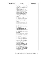
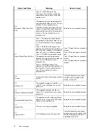
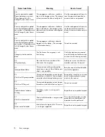
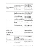
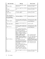
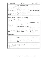
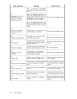
Page 67: ... disk volume The object or relationship already exists 1 Object Already Exists Report the error to product support The command or response buffer is not large enough to hold the specified num ber of items This can be caused by a user or program error 2 Supplied Buffer Too Small Report the error to product support The handle is already assigned to an existing object This can be caused by a user or ...

Page 68: ... device addition policy Storage cell set name Storage cell set time Storage cell set volume replacement delay Storage cell free command lock Storage cell set console lun id The supplied handle is invalid This can indicate a user error program error or a storage cell in an uninitialized state In the following cases the storage cell is in an uninitialized state but no action is required Storage cell...

Page 69: ...duct support There is no firmware image stored for the specified image number 20 No Image The disk device must be in either maintenance mode or in a re served state for the specified oper ation to proceed The disk device is not in a state to allow the specified operation 21 No Permission Create a storage cell and retry the operation The operation requires a storage cell to exist 22 Storage system ...

Page 70: ...eserved state before it can be erased Case 8 Delete the virtual disks or LUN presentations before uninitializing the storage cell Case 9 Delete the LUN presentations before deleting the EVA host Case 10 Report the error to product support Case 11 Resolve the situation before attempting the operation again Case 12 Resolve the situation before attempting the operation again Case 13 This may indicate...

Page 71: ...on cannot be resolved Case 7 Physical Store erase volume The disk is a part of a disk group and cannot be erased Case 8 Storage cell discard The storage cell contains one or more virtual disks or LUN presentations Case 9 Storage cell client discard The EVA host contains one or more LUN presentations Case 10 SCVD discard The virtual disk contains one or more derived units and cannot be discarded Th...

Page 72: ...peration cannot be performed because the target disk volume does not exist This can indicate a user or program error Case 4 GROUP get name The operation cannot be performed because the Continuous Access group does not exist This can indicate a user or program error 27 Target Object Does Not Exist Verify the hardware connections and that communication to the device is successful A timeout has occur...

Page 73: ...the error to product support The specified SCVD does not have a lo gical disk associated with it This can indicate a user or program error 41 No Logical Disk for Vdisk Delete the associated presenta tion s and retry the request The virtual disk specified is already presented to the client and the requested operation is not allowed 42 Logical disk Presented Report the error to product support The r...

Page 74: ...ioning correctly The Continuous Access group is not functioning 51 Storage system connection down Add one or more virtual disks as members and retry the request No virtual disks are members of the Continuous Access group 52 DR group empty Retry the request with valid attrib utes for the operation The request cannot be performed be cause one or more of the attributes spe cified is incompatible 53 I...

Page 75: ... size allowed Case 3 The presented user space exceeds the maximum size allowed Case 4 The presented user space exceeds the maximum size allowed Case 5 The size specified exceeds the maximum size allowed Case 6 The maximum number of EVA hosts already exist on the destination storage cell Case 7 The maximum number of EVA hosts already exist on the destination storage cell Case 8 The maximum number o...

Page 76: ... failed write op eration 73 Image Write Error Case 1 No action required Case 2 No action required Case 3 If a snapclone operation is in progress wait until the snapclone operation has completed and retry the operation Otherwise the operation cannot be performed on this virtual disk Case 4 No action required Case 5 No action required Case 1 The operation cannot be per formed because the virtual dis...

Page 77: ...sage to a reserved state and 80 retry the request Invalid Volume Usage Case 1 The disk volume is already a part of a disk group 80 Invalid Volume Usage Report the error to product support Case 2 The disk volume usage cannot be modified as the minimum number of disks exist in the disk group Resolve the condition by adding additional disks and retry the re quest The disk volume usage cannot be modi ...

Page 78: ...se the Continuous Access group is in a failsafe locked state 89 Failsafe Locked Retry the request later The disk cache data need to be flushed before the condition can be resolved 90 Data Flush Incomplete Report the error to product support The disk group is in a redundancy mirrored inoperative state and the re quest cannot be completed 91 Redundancy Mirrored Inoperative Select another LUN number ...

Page 79: ...ormed on a Continuous Access connection that is up 99 The DR operation can only be completed when the source destination connection is down If you are doing a destination DR deletion make sure the connection link to the source DR system is down or do a failover operation to make this system the source The storage system password may have been re configured or re moved The management software must ...

Page 80: ...Error messages 80 ...
Page 81: ...A or B of the equipment Class B devices have an FCC logo or FCC ID on the label Class A devices do not have an FCC logo or FCC ID on the label After the class of the device is determined see the corresponding statement in the following sections FCC Class A certification This equipment generates uses and may emit radio frequency energy The equipment has been type tested and found to comply with the...

Page 82: ...mined by turning the equipment off and on the user is encouraged to try to correct the interference by one or more of the following measures Reorient or relocate the receiving antenna Increase the separation between the equipment and receiver Connect the equipment into an outlet on a circuit that is different from that to which the receiver is connected Consult the dealer or an experienced radio o...

Page 83: ...ces and Radiological Health CDRH of the U S Food and Drug Administration implemented regulations for laser products on August 2 1976 These regulations apply to laser products manufactured from August 1 1976 Compliance is mandatory for products marketed in the United States Certification and classification information This product contains a laser internal to the Optical Link Module OLM for connect...

Page 84: ...nity EN61000 3 2 IEC61000 3 2 Power Line Harmonics EN61000 3 3 IEC61000 3 3 Power Line Flicker EN60950 IEC950 Product Safety Notice for France DECLARATION D INSTALLATION ET DE MISE EN EXPLOITATION d un matériel de traitement de l information ATI classé A en fonction des niveaux de perturbations radioélectriques émis définis dans la norme européenne EN 55022 concernant la Compatibilité Electromagné...

Page 85: ...ace odpadu pom že uchovat p írodní prost edí a zajistí takový zp sob recyklace který ochrání zdraví a životní prost edí lov ka Další informace o možnostech odevzdání odpadu k recyklaci získáte na p íslušném obecním nebo m stském ú ad od firmy zabývající se sb rem a svozem odpadu nebo v obchod kde jste produkt zakoupili Estonian notice Seadmete jäätmete kõrvaldamine eramajapidamistes Euroopa Liidus...

Page 86: ...r obtenir plus d informations sur les centres de collecte et de recyclage des appareils mis au rebut veuillez contacter les autorités locales de votre région les services de collecte des ordures ménagères ou le magasin dans lequel vous avez acheté ce produit German notice Entsorgung von Altgeräten aus privaten Haushalten in der EU Das Symbol auf dem Produkt oder seiner Verpackung weist darauf hin ...

Page 87: ...elettroniche La raccolta differenziata e il corretto riciclo delle apparecchiature da smaltire permette di proteggere la salute degli individui e l ecosistema Per ulteriori informazioni relative ai punti di raccolta delle apparecchiature contattare l ente locale per lo smaltimento dei rifiuti oppure il negozio presso il quale è stato acquistato il prodotto Korean Communication Committee notice Lat...

Page 88: ...ospodarki odpadami lub sklepem w którym zakupiono produkt Portuguese notice Descarte de Lixo Elétrico na Comunidade Européia Este símbolo encontrado no produto ou na embalagem indica que o produto não deve ser descartado no lixo doméstico comum É responsabilidade do cliente descartar o material usado lixo elétrico encaminhando o para um ponto de coleta para reciclagem A coleta e a reciclagem selet...

Page 89: ...servar los recursos naturales y a garantizar el reciclado de estos residuos de forma que se proteja el medio ambiente y la salud Para obtener más información sobre los puntos de recogida de residuos eléctricos y electrónicos para reciclado póngase en contacto con su ayuntamiento con el servicio de eliminación de residuos domésticos o con el establecimiento en el que adquirió el producto Swedish no...

Page 90: ...country specific regulatory requirements as an individual item or as part of an assembly The product label see Figure 26 specifies the regulations with which the product complies NOTE Components without an individual product certification label are qualified as part of the next higher assembly for example enclosure rack or tower Regulatory notices and specifications 90 ...

Page 91: ...NOTE The certification symbols on the label depend upon the certification level For example the FCC Class A certification symbol is not the same as the FCC Class B certification symbol HP StorageWorks 6400 8400 Enterprise Virtual Array user guide 91 ...

Page 92: ...Regulatory notices and specifications 92 ...

Page 93: ...n event display A problem that generates the Termination Event display prevents the system from performing a specific function or process You can use the information in this display see GUI Termination Event Display to diagnose and correct the problem NOTE The major differences between the Termination Event display and the Event display are The Termination Event display includes a Code Flag field ...

Page 94: ...d Evt No Event Number A hexadecimal number in the range 0 FF that is the software component identification number CAC Corrective Action Code A specific action to correct the problem EIP Type Event Information Packet Type A hexadecimal character that defines the event inform ation format Description The problem that generated the event Fault management displays When you do not have access to the GU...

Page 95: ...data about the selected error Interpreting fault management information Each version of HP Command View EVA includes an ASCII text file that defines all the codes that the authorized service representative can view either on the GUI or on the OCP IMPORTANT This information is for the exclusive use of the authorized service representative The file name identifies the controller model file type XCS ...

Page 96: ...p and then restart the controller 1 DO NOT perform a crash dump just restart the controller 3 DO NOT perform a crash dump DO NOT restart the controller Dump Restart Control Codes These hexadecimal codes supplement the Termination Code information to identify the faulty element and the recommended corrective action Corrective Action Codes CAC These decimal codes identify software associated with th...

Page 97: ...ing rails and needed room for any mounting hardware such as screws clip nuts etc Figure 29 shows the dimensions required for the mounting space for the EVA product line It does not show required space for additional HP components such as servers Figure 29 Mounting space dimensions EIA310 D standards The rack must meet the Electronic Industries Association EIA Standard 310 D Cabinets Racks and Asso...

Page 98: ... made to allow for some margin of safety when estimating configuration CG Estimating the configuration CG requires measuring the CG of the cabinet the product will be installed in Use the following formula ΣdcomponentW dsystem cgW where dcomponent the distance of interest and W Weight The distance of a component is its CG s distance from the inside base of the cabinet For example if a loaded disk ...

Page 99: ...n of the system If at all possible it is best to configure non HP cabinets in a like manner Environmental and operating specifications This section identifies the product environmental and operating specifications NOTE Further testing is required to update the information in Tables 45 47 Once testing is complete these tables will be updated in a future release UPS Selection This section provides i...

Page 100: ...standby battery R1500 49 23 5 100 63 32 6 80 161 57 13 50 290 146 34 20 R3000 20 5 100 30 6 5 80 45 12 50 120 40 20 R5500 46 24 7 100 60 31 9 80 106 61 19 50 303 169 59 20 R12000 18 11 5 100 24 15 7 80 41 28 14 50 101 69 43 20 Table 24 EVA8400 UPS loading of UPS capacity Watts Enclosures R12000 R5500 41 0 4920 12 Non standard rack specifications 100 ...

Page 101: ...ding of UPS capacity Watts Enclosures R12000 R5500 R3000 26 8 71 4 3214 8 23 6 63 0 2837 7 20 5 54 6 91 1 2460 6 17 3 46 2 77 2 2083 5 14 2 37 9 63 2 1707 4 11 1 29 5 49 3 1330 3 7 9 21 2 35 3 953 2 4 8 12 8 21 4 577 1 Shock and vibration specifications Table 26 lists the product operating shock and vibration specifications This information applies to products weighing 45 Kg 100 lbs or less HP Sto...

Page 102: ...tion applied in all three axes both positive and negative directions Sine sweep vibration from 5 Hz to 500 Hz to 5 Hz at 0 1 G peak with 0 020 displacement limitation below 10 Hz Sweep rate of 1 octave minute Test performed in all three axes Random vibration at 0 25 G rms level with uniform spectrum in the frequency range of 10 to 500 Hz Test performed for two minutes each in all three axes Drives...

Page 103: ...tions with these operating systems In addition cluster configurations of both OpenVMS and Tru64 UNIX provide enhanced availability and security To achieve availability within cluster configurations each member should be configured with its own HBA s and connectivity to shared LUNs Cluster configuration will not be discussed further within this appendix as the enhanced availability requires both ad...

Page 104: ...erver 2003 32 bit Novell NetWare Linux and IBM AIX operating systems the zones consist of the single path HBA systems and one HSV controller port On OpenVMS and Tru64 UNIX operating systems the zones consist of the single HBA systems and two HSV controller ports This will result in a configuration where there are two paths per device or multiple paths Recommended mitigations EVA is designed for th...

Page 105: ...ers See the HP StorageWorks SAN Design Reference Guide at the following HP website for additional information about zoning http h18006 www1 hp com products storageworks san documentation html To connect a single path HBA server to a SAN switch 1 Plug one end of the Fibre Channel cable into the HBA on the server 2 Plug the other end of the cable into the switch Figure 30 and Figure 31 represent con...

Page 106: ... server without OpenVMS or Tru64 UNIX 6 SAN switch 2 1 Network interconnection 7 Fabric zone 2 Single HBA server 8 Controller A 3 Dual HBA server 9 Controller B 4 Management server 5 SAN switch 1 Single Path Implementation 106 ...

Page 107: ...abric as servers with multiple HBAs Single path HBA server cannot share LUNs with any other HBAs In the use of snapshots and snapclones the source virtual disk and all associated snapshots and snapclones must be presented to the single path hosts that are zoned with the same controller In the case of snapclones after the cloning process has completed and the clone becomes an ordinary virtual disk ...

Page 108: ...en written to storage NOTE For additional risks see Table 27 on page 123 Limitations HP Continuous Access EVA is not supported with single path configurations Single path HBA server is not part of a cluster Booting from the SAN is not supported Figure 32 HP UX configuration 5 SAN switch 1 1 Network interconnection 6 SAN switch 2 2 Host 1 7 Controller A 3 Host 2 8 Controller B 4 Management server S...

Page 109: ...sk you may present that virtual disk as you would any other ordinary virtual disk HBA configuration Host 1 is a single path HBA host Host 2 is a multiple HBA host with multi pathing software See Figure 33 Risks Single path failure will result in loss of connection with the storage system Single path failure may cause the server to reboot Controller shutdown puts controller in a failed state that r...

Page 110: ...ements Switch zoning or controller level SSP must be used to ensure each single path HBA has an exclusive path to its LUNs Single path HBA server can be in the same fabric as servers with multiple HBAs Single path HBA server cannot share LUNs with any other HBAs HBA configuration Hosts 1 and 2 are single path HBA hosts Host 3 is a multiple HBA host with multi pathing software See Figure 34 Single ...

Page 111: ...em Single path failure may cause the server to reboot Controller shutdown puts controller in a failed state that results in loss of data accessibility and loss of host data that has not been written to storage NOTE For additional risks see Table 28 on page 124 Limitations HP Continuous Access EVA is not supported with single path configurations Single path HBA server is not part of a cluster Booti...

Page 112: ...ler In the case of snapclones after the cloning process has completed and the clone becomes an ordinary virtual disk you may present that virtual disk as you would any other ordinary virtual disk HBA configuration Host 1 is a single path HBA host Host 2 is a multiple HBA host with multi pathing software See Figure 35 Risks Single path failure may result in loss of data accessibility and loss of ho...

Page 113: ...HBA server can be in the same fabric as servers with multiple HBAs In the use of snapshots and snapclones the source virtual disk and all associated snapshots and snapclones must be presented to the single host that are zoned with the same controller In the case of snapclones after the cloning process has completed and the clone becomes an ordinary virtual disk you may present that virtual disk as...

Page 114: ...ost Upon re establishment of the path a retransmit can be performed to recover whatever data may have been lost during the outage The option to retransmit data after interruption is application dependent NOTE For additional risks see Table 30 on page 125 Figure 36 Tru64 UNIX configuration 5 SAN switch 1 1 Network interconnection 6 SAN switch 2 2 Host 1 7 Controller A 3 Host 2 8 Controller B 4 Mana...

Page 115: ...t are zoned with the same controller In the case of snapclones after the cloning process has completed and the clone becomes an ordinary virtual disk you may present that virtual disk as you would any other ordinary virtual disk HBA configuration Host 1 is a single path HBA host Host 2 is a dual HBA host See Figure 37 Risks For nonclustered nodes with a single path HBA a path failure from the HBA ...

Page 116: ...r controller level SSP must be used to ensure each single path HBA has an exclusive path to its LUNs Single path HBA server cannot share LUNs with any other HBAs HBA configuration Host 1 is a single path HBA host with NetWare Host 2 is a dual HBA host with multi pathing software See Figure 38 Risks Single path failure will result in a loss of connection with storage devices Single Path Implementat...

Page 117: ...onfiguration 5 SAN switch 1 1 Network interconnection 6 SAN switch 2 2 Single HBA server 7 Controller A 3 Dual HBA server 8 Controller B 4 Management server Linux 32 bit configuration Requirements Switch zoning or controller level SSP must be used to ensure each single path HBA has an exclusive path to its LUNs All nodes with direct connection to a disk must have the same access paths available to...

Page 118: ...disk you may present that virtual disk as you would any other ordinary virtual disk HBA configuration Host 1 is a single path HBA Host 2 is a dual HBA host with multi pathing software See Figure 39 Risks Single path failure may result in data loss or disk corruption NOTE For additional risks see Table 32 on page 126 Limitations HP Continuous Access EVA is not supported with single path configurati...

Page 119: ...f snapclones after the cloning process has completed and the clone becomes an ordinary virtual disk you may present that virtual disk as you would any other ordinary virtual disk Linux 64 bit servers can support up to14 single or dual path HBAs per server Switch zoning and SSP are required to isolate the LUNs presented to each HBA from each other HBA configuration Host 1 and 2 are single path HBA ...

Page 120: ...e fabric as servers with multiple HBAs Single path HBA server cannot share LUNs with any other HBAs In the use of snapshots and snapclones the source virtual disk and all associated snapshots and snapclones must be presented to the single path hosts that are zoned with the same controller In the case of snapclones after the cloning process has completed and the clone becomes an ordinary virtual di...

Page 121: ...data that has not been written to storage NOTE For additional risks see Table 33 on page 127 Limitations HP Continuous Access EVA is not supported with single path configurations Single path HBA server is not part of a cluster Booting from the SAN is not supported Figure 41 IBM AIX Configuration 5 SAN switch 1 1 Network interconnection 6 SAN switch 2 2 Single HBA server 7 Controller A 3 Dual HBA s...

Page 122: ...th hosts that are zoned with the same controller In the case of snapclones after the cloning process has completed and the clone becomes an ordinary virtual disk you may present that virtual disk as you would any other ordinary virtual disk HBA configuration Host 1 is a single path HBA Host 2 is a dual HBA host with multi pathing software See Figure 42 Risks Single path failure may result in data ...

Page 123: ...y critical event on UNIX Can cause loss of system disk Server failure host power cycled Short term Data transfer stops Possible I O errors Long term Job hangs cannot umount disk fsck failed disk corrupted need mkfs disk Switch failure SAN switch disabled Short term Data transfer stops Possible I O errors Long term Job hangs cannot umount disk fsck failed disk corrupted need mkfs disk Controller fa...

Page 124: ... critical shelves offline Volume not accessible Server cold reboot data lost Check disk when rebooting Controller failure Controller momentarily in failed state server keeps copying All data copied no interruption Event error warning error detected during paging operation Controller restart Write delay volume inaccessible Host hangs and restarts Server path failure Write delay volume disappears se...

Page 125: ... to panic Possible data loss from unfinished or unflushed writes File system check may be needed upon reboot Switch failure SAN switch disabled I O fails over to the surviving path No data is lost or corrupted Controller failure OpenVMS OS will report the volume in a Mount Verify state until the MVTIMEOUT limit is exceeded when it then marks the volume as Mount Verify Timeout No data is lost of co...

Page 126: ...t I O to device stops with I O errors indicated on server console Applications using lost connection halts Server restart recommended but may not be necessary Volume repair or NSS rebuild runs when volumes are mounted Server path failure I O to device stops with I O errors indicated on server console Applications using lost connection halts Server restart recommended but may not be necessary Volum...

Page 127: ...opying survived Server failure host power cycled Short term Data transfer stops Possible I O errors Long term Repeated error messages in errpt output System reboot causes loss of data on disk Must crfs disk Switch failure SAN switch disabled Short term Data transfer stops Possible I O errors Long term Repeated error messages in errpt output System reboot causes loss of data on disk Must crfs disk ...

Page 128: ...ot system fsck should be run on any failed disks before remounting Controller failure Short term I O suspended possible data loss Long term I O halts with I O errors data loss Cannot reload driver need to reboot system fsck should be run on any failed disks before remounting Controller restart Short I O suspended possible data loss Long I O halts with I O errors data loss HBA driver must be reload...

Page 129: ...identify the loop ports This value becomes the last byte of the address identifier for each public port on the loop allocation policy Storage system rules that govern how virtual disks are created Allocate Completely and Allocate on Demand are the two rules used in creating virtual disks Allocate Completely The space a virtual disk requires on the physical disks is reserved even if the virtual dis...

Page 130: ...the baud rate may be lower than the code bit rate bay The physical location of an element such as a drive I O module EMU or power supply in a drive enclosure Each bay is numbered to define its location bidirectional Also called Bi Di The movement of optical signals in opposite directions through a common fiber cable such as the data flow path typically on a parallel printer port A parallel port ca...

Page 131: ...ion report A three element code generated by the EMU in the form where e t is the element type a hexadecimal number en is the element number a decimal number and ec is the condition code a decimal number console LUN A SCSI 3 virtual object that makes a controller pair accessible by the host before any virtual disks are created Also called a communication LUN console LUN ID The ID that can be assig...

Page 132: ...mits a user to view detailed information about a controller fault device channel A channel used to connect storage devices to a host I O bus adapter or intelligent controller device ports Controller pair device ports connected to the storage system s physical disk drive array through the Fibre Channel drive enclosure Also called a device side port device side ports See device ports DIMM Dual Inlin...

Page 133: ... a loop pair dual power supply configuration See redundant power configuration dynamic capacity expansion A storage system feature that provides the ability to increase the size of an existing virtual disk Before using this feature you must ensure that your operating system supports capacity expansion of a virtual disk or LUN EIA Electronic Industries Alliance A standards organization specializing...

Page 134: ...r pair shares an enclosure number If the system has an expansion rack the enclosures in the expansion rack are numbered from 15 to 24 starting at the bottom enclosure services Those services that establish the mechanical environmental electrical environmental and external indicators and controls for the proper operation and maintenance of devices with an enclosure as described in the SES SCSI 3 En...

Page 135: ...ort A port which is capable of supporting an attached arbitrated loop This port on a loop will have the AL_PA hexadecimal address 00 loop ID 7E giving the fabric the highest priority access to the loop A loop port is the gateway to the fabric for the node ports on a loop failover The process that takes place when one controller assumes the workload of a failed companion controller Failover continu...

Page 136: ...irty data from cache to a storage media FMC Fault Management Code The HP Command View EVA display of the Enterprise Storage System error condition information form factor A storage industry dimensional standard for 3 5inch 89 mm and 5 25inch 133 mm high storage devices Device heights are specified as low profile 1inch or 25 4 mm half height 1 6inch or 41 mm and full height 5 25inch or 133 mm FPGA ...

Page 137: ...t Bus Adapter See also FCA host A computer that runs user applications and uses or can potentially use one or more virtual disks created and presented by the controller pair Host Bus Adapter See FCA host computer See host host link indicator The HSV Controller display that indicates the status of the storage system Fibre Channel links host ports A connection point to one or more hosts through a Fi...

Page 138: ...t disk group input output module See I O module intake temperature See ambient temperature interface A set of protocols used between components such as cables connectors and signal levels JBOD Just a Bunch of Disks A number of disks connected to one or more controllers K Kilo A scientific notation denoting a multiplier of one thousand 1 000 KB Kilobyte A unit of measurement defining either storage...

Page 139: ...it HSV Controller number that identifies a specific event that terminated an operation Valid numbers range from 00 to 31 LUN Logical Unit Number A SCSI convention used to identify elements The host sees a virtual disk as a LUN The LUN address a user assigns to a virtual disk for a particular host will be the LUN at which that host will see the virtual disk management agent The HP Command View EVA ...

Page 140: ... The ability of the devices to operate correctly may be reduced if additional failures occur UNRECOVERABLE and CRITICAL errors have precedence over this condition This condition has precedence over INFORMATION condition Early correction can prevent the loss of data node port A device port that can operate on the arbitrated loop topology non OFC Open Fibre Control A laser transceiver whose lower in...

Page 141: ...hat is the equivalent of 250 1 125 899 906 842 624 bytes or 1 024 terabytes physical disk A disk drive mounted in a drive enclosure that communicates with a controller pair through the device side Fibre Channel loops A physical disk is hardware with embedded software as opposed to a virtual disk which is constructed by the controllers Only the controllers can communicate directly with the physical...

Page 142: ...st by allowing the controller to satisfy the request from the cache memory rather than from the disk drives reconstruction The process of regenerating the contents of a failed member data The reconstruction process writes the data to a spare set disk and incorporates the spare set disk into the mirrorset striped mirrorset or RAID set from which the failed member came red wine colored A convention ...

Page 143: ...rial transmission A method of transmission in which each bit of information is sent sequentially on a single channel rather than simultaneously as in parallel transmission SES SCSI 3 Enclosures Services Those services that establish the mechanical environment electrical environment and external indicators and controls for the proper operation and maintenance of devices within an enclosure small co...

Page 144: ... to optical signals at the point where the fiber cables connect to the FC elements such as hubs controllers or adapters uninitialized system A state in which the storage system is not ready for use See also initialization UNRECOVERABLE Condition A drive enclosure EMU condition report that occurs when one or more elements inside the enclosure have failed and have disabled the enclosure The enclosur...

Page 145: ... protection All data blocks are mirrored or written twice on separate physical disks For read requests the block can be read from either disk which can increase performance Mirroring takes the most storage space because twice the storage capacity must be allocated for a given amount of data Vraid5 A virtualization technique that uses parity striping to provide moderate data protection Parity is a ...

Page 146: ...WWN World Wide Name A unique Fibre Channel identifier consisting of a 16 character hexadecimal number A WWN is required for each Fibre Channel communication port Glossary 146 ...

Page 147: ...e flag 94 Command View GUI displaying events Command View GUI displaying termination events connection suspended 75 connectors power IEC 309 receptacle 29 power NEMA L6 30R 29 protecting 53 controller cabling 28 connectors 28 initial setup 42 status indicators conventions document 13 text symbols 14 Corrective Action Code See CAC Corrective Action Codes See CAC country specific certifications 90 c...

Page 148: ...oller HSV controller shutdown 57 HSV Controllers initial setup 42 I I O modules bidirectional 18 IDX code display 95 image already loaded 76 image incompatible with configuration 76 image too large 76 image write error 76 implicit LUN transition 50 incompatible attribute 74 indicators battery status battery status 24 push buttons 25 INITIALIZE LCD 57 initializing the system defined 57 invalid para...

Page 149: ...s cleaning supplies dust covers 54 proxy reads 50 push button indicators push buttons definition 25 navigating with R rack non standard specifications 97 rack configurations 29 regulatory compliance notices European Union Japan Taiwan WEEE recycling notices regulatory notices regulatory compliance notices laser devices regulatory compliance notices cables 82 Class A 82 Class B 82 modifications 82 ...

Page 150: ... termination event GUI display Termination Code See TC text symbols 14 time not set 73 timeout 72 transport error 72 turning off power U Uninitializing 58 uninitializing the system universal disk drives unknown id 72 unknown parameter handle 72 unrecoverable media error 72 UPS selecting 99 using the OCP V Vdisk DR group member 74 Vdisk DR log unit 74 Vdisk not presented 74 version information disp...

Reviews: