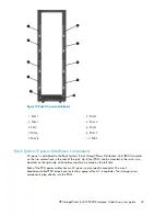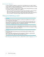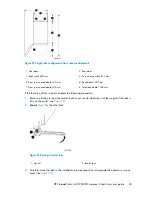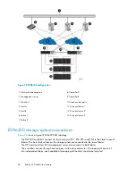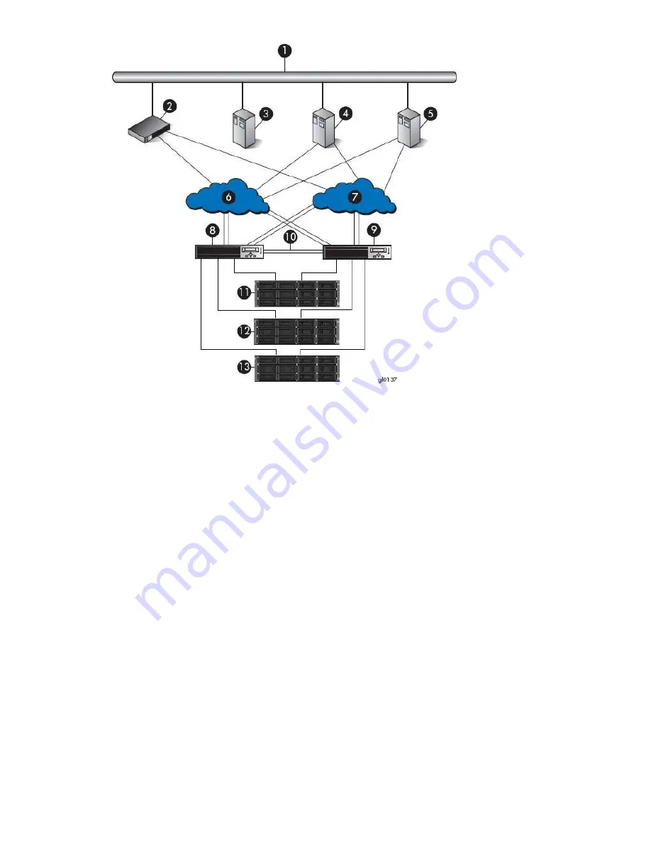
Figure 22 EVA8400 configuration
.
8 Controller A
1 Network interconnection
9 Controller B
2 Management server
10 Cache mirror ports
3 Non-host
11 Drive enclosure 1
4 Host A
12 Drive enclosure 2
5 Host B
13 Drive enclosure 3
6 Fabric 1
7 Fabric 2
EVA6400 storage system connections
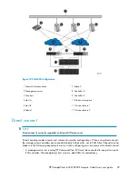
Figure 23
shows a typical EVA6400 SAN topology:
•
The HSV400 controllers connect via four host ports (FP1, FP2, FP3, and FP4) to the Fibre Channel
fabrics. The hosts that will access the storage system are connected to the same fabrics.
•
The HP Command View EVA management server also connects to both fabrics.
•
The controllers connect through one loop pair to the drive enclosures. The loop pair consists of
two independent loops, each capable of managing all the disks should one loop fail.
Enterprise Virtual Array startup
38
Summary of Contents for 6400/8400
Page 12: ...12 ...
Page 16: ...About this guide 16 ...
Page 60: ...EVA6400 8400 operation 60 ...
Page 66: ...Customer replaceable units 66 ...
Page 80: ...Error messages 80 ...


