2-36
Removal and Replacement
HP Omnibook 6000/6100
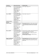
Component
Removal Procedure
Additional Steps
PCA, display interface
Plug-in module (page 2-5).
Hard disk drive (page 2-7).
Power button panel
(page 2-11).
Keyboard (page 2-15).
Heatsink (page 2-17).
Display assembly
(page 2-13).
Top case (page 2-20).
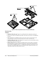
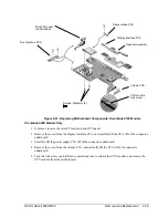
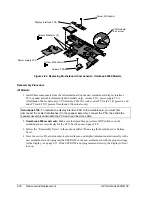
Remove the screw from the board (see the figure on
page 2-30), and carefully lift the board off of the
connector underneath.
Reassembly Notes: Make sure the DIP switches on
the new display interface PCA match the settings
shown on the label on the display cable, or you risk
damaging the display.
PCA, front antenna
(Omnibook 6100
wireless models only)
Plug-in module (page 2-5).
Hard disk drive (page 2-7).
Power button panel
(page 2-11).
Keyboard (page 2-15).
Heatsink (page 2-17).
Display assembly
(page 2-13).
Top case (page 2-20).
Motherboard (page 2-24).
Disconnect the cables from the mini-PCI card,
disconnect the flex cable from the motherboard, and
remove the motherboard. Gently release the cable
from the retaining clips. Remove the two screws that
hold the PCA in place.
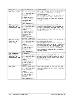
PCA, power supply
(Omnibook 6000
models only)
Plug-in module (page 2-5).
Hard disk drive (page 2-7).
Power button panel
(page 2-11).
Keyboard (page 2-15).
Heatsink (page 2-17).
Display assembly
(page 2-13).
Top case (page 2-20).
Carefully lift the board off of the connector underneath
(see the figure on page 2-30).
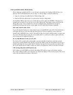
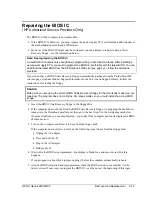
Reassembly Note: The BIOS IC on a new power
supply PCA contains only enough basic programming
to boot the Omnibook. After installing the new PCA,
you must reprogram the BIOS IC, preferably with the
latest BIOS. You can download the latest BIOS from
the HP Notebook Web site (see page vi)—follow the
directions provided.
PCA, motherboard
See page 2-22.
PCA, rear antenna
(Omnibook 6100
wireless models only)
Plug-in module (page 2-5).
Hard disk drive (page 2-7).
Power button panel
(page 2-11).
Keyboard (page 2-15).
Heatsink (page 2-17).
Display assembly
(page 2-13).
Remove the screw attaching the PCA to the top case,
remove the cover from mini-PCI card #1, disconnect
the cable from the mini-PCI card, and gently pull the
PCA out of the computer.
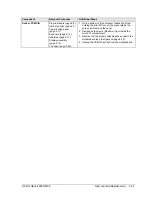
PCA, volume
Plug-in module (page 2-5).
Hard disk drive (page 2-7).
Power button panel
(page 2-11).
Keyboard (page 2-15).
Heatsink (page 2-17).
Display assembly
(page 2-13).
Top case (page 2-20).
Remove the screw from the board (Omnibook 6000
only), and carefully lift the board off of the connector
underneath.
Summary of Contents for 6100
Page 1: ... HP Omnibook 6000 6100 Service Manual ...
Page 22: ......
Page 60: ......
Page 94: ...4 2 Replaceable Parts HP Omnibook 6000 6100 Figure 4 1 Exploded View ...
Page 108: ......
Page 113: ......
Page 114: ...Part Number F3257 90025 Printed in U S A 6 01 ...

