background image

HP Omnibook 6000/6100

Replaceable Parts

4-11

Exchange

Omnibook

User-

Part Number

Part Number

Description

6100

6000

Repl.

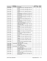
F2072-60913

F2072-69013

PCA, motherboard (Pentium)

F2072-60914

F2072-69014

PCA, motherboard (Celeron)

F2072-60915

PCA, display interface

F2072-60917

F2072-60917

Display assembly, 14.1” XGA

F2072-60918

F2072-60918

Display assembly, 15.0” XGA

F2072-60919

Socket, PCMCIA

F2072-60921

Tray, business card

Yes

F2072-60922

Module, weight-saving

Yes

F2072-60923

Screws, kit

Yes

F2072-60925

Mini-PCI panels, kit

F2072-60926

Feet/bumpers, kit

Yes

F2072-60928

Keyboard, US English

F2072-60929

Keyboard, International English

F2072-60930

Keyboard, Greek

F2072-60931

Keyboard, Turkish

F2072-60932

Keyboard, UK English

F2072-60933

Keyboard, French Canadian

F2072-60934

Keyboard, German

F2072-60935

Keyboard, Spanish

F2072-60936

Keyboard, French

F2072-60937

Keyboard, Japanese

F2072-60938

Keyboard, Norwegian

F2072-60939

Keyboard, Swiss

F2072-60940

Keyboard, Swedish/Finnish

F2072-60941

Keyboard, Danish

F2072-60942

Keyboard, Italian

F2072-60943

Keyboard, Czech

F2072-60944

Keyboard, Belgian

F2072-60945

Keyboard, Hebrew

F2072-60946

Keyboard, Hungarian

F2072-60947

Keyboard, Russian

F2072-60948

Keyboard, Portuguese

F2072-60949

Keyboard, Arabic English

F2072-60950

Keyboard, Traditional Chinese

F2072-60987

Training set, Series 00-A

F2072-60994

Card, mini-PCI (LAN/modem w/regulatory)

Yes

F2072-60995

Panel, power button

Yes

F2072-60999

Covers, service kit

F2072-69115

Drive, hard disk (30 GB, 9.5 mm, IBM Diablo)

Yes

F2073-60948

Recovery CD, Norwegian, W98 (Mfg. P/N
F2072-12048)

F2073-60949

Recovery CD, Finnish, W98 (Mfg. P/N F2072-
12049)

F2073-60950

Recovery CD, Danish, W98 (Mfg. P/N F2072-
12050)

F2073-60952

Recovery CD, German, Dutch, W98 (Mfg. P/N
F2072-12052)

F2073-60954

Recovery CD, English, NT4 (Mfg. P/N F2072-
12054)

Summary of Contents for 6100

Page 1: ... HP Omnibook 6000 6100 Service Manual ...

Page 2: ...ritten permission of Hewlett Packard Co is also prohibited Portions of the programs that control this product may also be copyrighted by Microsoft Corporation SystemSoft Corp Phoenix Technologies Ltd ATI Technologies Inc and Adobe Systems Incorporated See the individual programs for additional copyright notices This product incorporates copyright protection technology that is protected by method c...

Page 3: ...sink with Fan HP Authorized Service Providers Only 2 17 Removing the CPU Module HP Authorized Service Providers Only 2 19 Removing the Top Case HP Authorized Service Providers Only 2 21 Removing the Motherboard or Bottom Case HP Authorized Service Providers Only 2 24 Replacing the Motherboard 2 28 Replacing the Bottom Case 2 32 Repairing the BIOS IC HP Authorized Service Providers Only 2 33 Removi...

Page 4: ...Unplugging the Keyboard Cables 2 16 Figure 2 13 Removing the Heatsink 2 17 Figure 2 14 Removing the CPU Module 2 19 Figure 2 15 Removing the Top Case Omnibook 6100 Models 2 22 Figure 2 16 Removing the Top Case Omnibook 6000 Models 2 23 Figure 2 17 Removing the Motherboard Omnibook 6100 Models 2 25 Figure 2 18 Removing the Motherboard Omnibook 6000 Models 2 26 Figure 2 19 Installing Docking Doors 2...

Page 5: ...Recommended Screw Torques 2 2 Table 2 4 Replacing Small Parts User Replaceable 2 12 Table 2 5 Motherboard and PCA Compatibility 2 28 Table 2 6 Removing Omnibook Components 2 34 Table 3 1 Scope of Diagnostic Tools 3 5 Table 3 2 Troubleshooting Suggestions 3 6 Table 3 3 Omnibook Diagnostic Error Codes 3 20 Table 3 4 POST Terminal Error Beep Codes 3 24 Table 3 5 POST Messages 3 25 Table 3 6 Sycard PC...

Page 6: ...ebook Web Site http www hp com notebooks http www europe hp com notebook European mirror No usage restriction HP Partnership Web http partner americas hp com Restricted to Authorized Resellers only HP Asia Pacific Channel Support Centre for DPSP Partners http www hp com au Restricted to DPSP Partners only America Online Keyword HP Call 800 827 6364 for membership within the US CompuServe GO HP Cal...

Page 7: ...00 MHz 15 0 XGA 18 GB DVD FDD 128 MB None F2140xy Celeron 650 MHz 14 1 XGA 6 GB CD ROM FDD 64 MB SW Modem F2141xy Celeron 650 MHz 14 1 XGA 6 GB CD ROM FDD 64 MB SW Modem F2142xy Celeron 650 MHz 14 1 XGA 6 GB CD ROM FDD 64 MB None F2143xy Celeron 650 MHz 14 1 XGA 6 GB CD ROM FDD 64 MB None F2144xy Pentium III 650 MHz 14 1 XGA 6 GB CD ROM FDD 64 MB Modem LAN F2145xy Pentium III 650 MHz 14 1 XGA 6 GB...

Page 8: ...s XP Home J for Windows XP Professional A y suffix none T G or U is a marketing distinction only Intel Mobile Pentium III or III M with SpeedStep Technology or Intel Mobile Celeron processor Table 1 2 Product Comparisons Omnibook 6100 Omnibook 6000 Omnibook 500 Processor Pentium III M 933 to 1133 MHz Celeron 550 to 750 MHz or Pentium III 600 to 1000 MHz Celeron 500 or 600 MHz or Pentium III 600 to...

Page 9: ...ilt in microphone 6 Pointing stick pointing device 7 Touch pad click and scroll buttons 8 Main status lights left to right power mode hard disk activity charging status for main battery and charging status for secondary battery 9 Module eject latch 10 Volume control 11 Audio off button and audio off light 12 Audio jacks left to right audio out headphones external microphone audio in 13 Infrared po...

Page 10: ...r or other parallel device or to connect the floppy disk drive externally 22 External monitor port 23 Docking port 24 AC adapter jack 25 Modem port on certain models 26 LAN port 27 PC Card and CardBus slots upper and lower 28 Wireless on off button and indicator light on certain models Figure 1 3 Omnibook Bottom View 29 Plug in module bay Can contain a CD ROM or DVD drive floppy disk drive seconda...

Page 11: ...ght is on Press blue sleep button or click Start Suspend Windows 95 or Start Shutdown Standby Windows 98 and 2000 or allow timeout Press the blue sleep button to display your current session Hibernate mode Saves maximum power Saves current session to disk then shuts down Restores network connections Power mode status light is off Press Fn F12 or Click Start Shut Down Hibernate Windows 2000 or allo...

Page 12: ...not connected Secondary battery status Green The AC adapter is connected and the battery is fully charged Amber The AC adapter is connected and the battery is charging Red or blinking The battery has a fault Off The AC adapter is not connected a secondary battery is not installed or the battery is not charging The keyboard status lights located above the keyboard indicate the states of the keyboar...

Page 13: ...h keys Table 1 6 Fn Hot Keys Hot Key Effect Fn F1 Decreases the display brightness Fn F2 Increases the display brightness Fn F5 Toggles among the built in display an external display and simultaneous display on both Fn F7 Mutes the computer s speakers Fn F8 Toggles the built in keypad on and off Does not affect an external keyboard If Num Lock is on then the numeric functions are active otherwise ...

Page 14: ...the power button for 4 seconds until the display shuts down then press the blue sleep button to restart or if this fails Insert a straightened paper clip into the system off switch on the right side of the computer then press the blue sleep button to restart Figure 1 4 Resetting the Computer Note To boot from a floppy CD ROM or DVD drive in the module bay insert a bootable CD such as the Recovery ...

Page 15: ...ystem PCI bus and other I O Graphics Omnibook 6000 14 1 or 15 0 inch XGA active matrix TFT display 1024 768 or 15 0 inch SXGA 1400 1050 External monitors up to 1600 1200 64K or 16M colors and at least 75 Hz refresh rate only 60 Hz at 1400 1050 Zoomed Video support for lower PC Card slot 3D and OpenGL graphics support Celeron models ATI Mobility M graphics accelerator with 4 MB display RAM 2x AGP g...

Page 16: ...ot Agent support for PXE BINL BOOTP NCP IPX DHCP Modem Hardware based controllerless modem US Robotics or 3Com or software based ACLink modem Ambit mini PCI interface Data speed 56 Kbps V 90 maximum Fax speed 14 4 Kbps Class 1 and 2 Modulation V 21 V 22 V 22bis V 23 V 32 V 32bis V 34 V 90 X2 US Robotics and 3Com only Bell 103 Bell 212A Synchronous transfer V 80 Compression V 42bis MNP5 Error corre...

Page 17: ...tium III or Celeron processor Core logic Intel South Bridge PIIX4M chipset Graphics controller ATI Mobility M or M1 Audio controller ESS Maestro 3E and ESS ES1921 CardBus controller TI PCI 1420 Keyboard embedded controller National PC87570 BIOS flash SST28SF040 Super I O National NS97338 Omnibook 6100 CPU Intel Mobile Pentium III M processor Core logic Intel 830M ICH3M chipset Graphics controller ...

Page 18: ...e F2013A Floppy disk drive module F2015A DVD drive module F2017A CD ROM drive module F2022A B SuperDisk drive module F2026A CD read write drive module F2101A USB floppy disk drive cable F2107A DVD ROM CD RW drive module Power Options F1454A 60 watt AC adapter F1455A 75 watt auto airline power adapter F1781A UltraSlim AC Adapter F2011A Battery charger external F2014A Lithium ion secondary battery F...

Page 19: ... by Xircom F1643A B Realport 10 100 Mbps Ethernet 56 Kbps modem PC Card by Xircom F1782A 10 100 Mbps Ethernet 56 Kbps modem PC Card by 3Com F1985A 10 100 Mbps USB Ethernet adapter by 3Com F2135A B 802 11b wireless LAN access point F2136A B 802 11b wireless LAN PC Card F2196A Bluetooth PC Card by 3Com Docking F1451A B Port replicator F1452A B Mini dock F1453A Monitor stand short for F1451A and F145...

Page 20: ...ronic modules In addition the table on page 1 15 lists the roles that the replaceable modules play in each of the Omnibook s functional subsystems Figure 1 5 Replaceable Module Diagram Motherboard PCA Heatsink fan CPU module Volume PCA Hard disk drive Mini PCI card 1 Top case Power supply PCA Display interface PCA Display assembly Keyboard pointing stick Speakers SDRAM modules Rear antenna PCA Fro...

Page 21: ...0 Keyboard Top case Keyboard circuitry keyboard controller OB 6100 Keyboard controller OB 6000 keyboard BIOS OB 6000 Pointing stick sensor Touch pad sensor click buttons controller PS 2 output Audio Motherboard Display interface PCA Volume PCA Top case Speaker assembly OB 6100 Audio controller audio decoder speaker amplifier ZV controller Microphone External audio jacks headphone amplifier audio o...

Page 22: ......

Page 23: ...et rubber page 2 12 Heatsink with fan page 2 17 Keyboard page 2 15 Panel sound IR page 2 34 Panel mini PCI page 2 34 Panel power button page 2 11 Panel vent page 2 34 PCA display interface page 2 34 PCA power supply page 2 34 PCA motherboard page 2 22 PCA volume page 2 34 PCA front antenna page 2 34 PCA rear antenna page 2 34 Plug in module page 2 5 SDRAM module page 2 6 Socket PCMCIA page 2 34 Sp...

Page 24: ...al tool similar to OK Industries EX 5 Table 2 3 Recommended Screw Torques Screw Thread Size Torque cm kgf Torque in lbf M2 1 3 1 8 1 1 1 5 M2 5 2 11 mm long 3 0 3 5 2 6 3 0 M2 5 12 19 mm long 2 5 3 0 2 2 2 6 M3 3 0 3 5 2 6 3 0 Disassembly Flowchart The following diagram shows the general path you will use in disassembling the computer to access any particular component ...

Page 25: ...he top case motherboard or bottom case If removing only display assembly or hinge covers CPU module CMOS battery Hinge covers Rear antenna PCA wireless only PCMCIA socket Display interface PCA Power supply PCA OB 6000 only Volume PCA Mini PCI panel Vent panel Omnibook 6000 only Sound IR panel Docking doors PCMCIA doors Speaker assembly OB 6100 only Motherboard or bottom case Front antenna PCA wire...

Page 26: ... None Removal Procedure Slide the battery s release latch then lift the battery out of its compartment Figure 2 2 Removing the Battery Reassembly Notes Insert the front rounded end of the battery into the battery compartment on the bottom of the computer and lower the back end in until it clicks into place ...

Page 27: ...ug In Module User Replaceable Required Equipment None Removal Procedure 1 Press the button on the module release latch and slide the latch toward the front of the computer Figure 2 3 Removing a Module 2 Grasp the module and pull it out Figure 2 4 Removing a Module ...

Page 28: ...screwdriver Removal Procedure 1 Unplug the AC adapter if present and remove the battery Remove the secondary battery if one is installed 2 Turn the unit bottom side up loosen the one or two screws holding the SDRAM cover the cover may retain the screws and remove the cover 3 Release the two latches at the sides of the SDRAM module so the free edge of the board pops up 4 Pull the board out of the c...

Page 29: ... cover on the end of the drive so that its retainer tab is free of the computer casing then gently pull the hard drive out of the computer Figure 2 6 Removing the Hard Disk Drive 4 Remove all screws from the holder and drive case then lift the drive out of the holder 5 Notice that the hard drive has a pin connector attachment at one end Carefully remove this connector from the end of the drive Wor...

Page 30: ...tor back onto the pins on the end of the new hard drive Work at each end alternately so that the connector slides on evenly without bending the connector pins Important If you are installing a new hard drive create a Utility partition on the drive before loading any software see Creating a Utility Partition below Pin connector Screws M3 3mm 2 Screws M3 3mm 2 Screws M2 4mm 2 OB 6000 only ...

Page 31: ... DVD drive as the boot device 5 When the Recovery CD dialog box appears follow the displayed instructions If prompted accept the recommended partition size If you install the factory software the recovery process can take up to 10 minutes If you want to create the Utility partition without installing the factory software click Advanced and select the option to not install the operating system If y...

Page 32: ...ry Remove the secondary battery if one is installed 2 Loosen the screw holding the mini PCI cover the cover retains the screw and remove the cover Caution Be gentle when removing and attaching antenna cables from the mini PCI card Damage to cables or connectors can degrade performance 3 Detach all the cables from the board 4 Release the latches at the sides of the board so that the free edge of th...

Page 33: ...battery Remove the secondary battery if one is installed 2 Carefully insert the screwdriver blade under the power button panel along the edge shown below and gently pry up the center of the cover 3 Insert a thumb or finger under the center of the panel and lift the panel out Figure 2 9 Removing the Power Button Panel Reassembly Notes Insert the left end of the panel into the top case and press the...

Page 34: ... the screw in the mini PCI cover the cover retains the screw and remove the cover Cover SDRAM On the bottom of the computer loosen the one or two screws in the SDRAM module cover the cover may retain the screws and remove the cover Covers screw on display bezel Insert a small flat blade screwdriver under the cover and pry it loose To replace firmly press the adhesive side of the cover into the rec...

Page 35: ... 2 Remove the power button panel page 2 11 3 From the back of the computer remove the two screws near the PS 2 keyboard mouse port and the two near the AC adapter jack 4 From the bottom of the computer remove the two screws from the rear corners closest to the back edge 5 Open the display Remove the screw from the display s ground wire and disconnect the main cable 6 Remove any screws from the cen...

Page 36: ... risk damaging the display Omnibook 6100 Reprogram the BIOS IC preferably with the latest BIOS for display compatibility Omnibook 6000 If you change the DIP switches use the service utilities disk to reprogram the EEPROM see page 2 31 If the EEPROM is not programmed correctly the display will not turn on Screws M2 5 6mm 5 Screws M2 5 8mm 2 OB 6100 Screws M2 5 6mm 2 OB 6000 Screws M2 5 4 mm 1 on OB...

Page 37: ...f the computer was running recently 4 Remove the four retaining screws from the tabs along the back end of the keyboard Figure 2 11 Removing the Keyboard 5 Raise the back end of the keyboard then lift the keyboard out of the computer Be careful not to pull on the cables connecting the keyboard to the computer 6 Lay the keyboard face down on the top case slightly forward of its normal position Be c...

Page 38: ...own on the top case slightly forward of its normal position then reconnect the keyboard and pointing stick flex cables Slip the metal tabs on the bottom of the keyboard into their slots in the top case then lower the keyboard into place Caution Do not excessively bend or fold the keyboard cables Keyboard and pointing stick flex cables ...

Page 39: ...dary battery if one is installed 2 Remove these additional assemblies Power button panel page 2 11 Keyboard page 2 15 3 Disconnect the fan cable through the opening in the heatsink 4 Remove the five retaining screws 5 Lift the heatsink out of the unit Figure 2 13 Removing the Heatsink Screws M2 5 6mm 4 Fan cable Fan cable socket Screw M2 5 4mm Omnibook 6000 heatsink Omnibook 6100 heatsink Screws M...

Page 40: ... is not a spacer pad in the same location on the heatsink If both are present remove the spacer pad Caution Restore proper thermal contact when installing the heatsink Otherwise performance can be significantly degraded Carefully clean the heatsink and CPU surfaces and install a new thermal pad on the heatsink in these situations Required whenever you install a new CPU for any model Required whene...

Page 41: ...ve the battery Remove the secondary battery if one is installed 2 Remove these additional assemblies Power button panel page 2 11 Keyboard page 2 15 Heatsink page 2 17 3 Turn the lock screw one half turn counterclockwise to release the CPU module and remove the CPU module from the motherboard Figure 2 14 Removing the CPU Module CPU module lock screw CPU module screw placement varies among models P...

Page 42: ... next to the volume PCA They control the power level to the CPU in the SpeedStep high speed mode The settings to use depend on the speed of the CPU 900 1000MHz CPUs 1 ON 2 OFF 3 OFF 4 ON 5 ON 6 not used Other CPUs 1 ON 2 ON 3 ON 4 OFF 5 ON 6 not used Caution Restore proper thermal contact when installing the heatsink Otherwise performance can be significantly degraded Carefully clean the heatsink ...

Page 43: ...ght corner cover may come off more easily if you slide the plug in module latch forward Omnibook 6100 Models Only Perform steps 1 through 3 above 1 Remove the six retaining screws from the bottom case 2 Remove the two retaining screws located just inside the hard disk drive compartment 3 Remove the single screw inside the battery compartment 4 From the top of the computer disconnect the touch pad ...

Page 44: ... compartment 4 From the top of the computer disconnect the speaker wires and the touch pad flex cable 5 Remove both retaining screws one to the left of the right speaker and one to the right of the touch pad flex cable 6 Remove the screw from the tab near the upper click buttons 7 Raise the back of the top case then lift it off the computer Screws M2 5x4mm 2 PCMCIA doors Screws M2 5x8mm 4 Screws M...

Page 45: ...e then move the plug in module latch forward and snap the cover over the latch and into place Wireless models only If you are replacing the rear antenna PCA place the PCA in its position near the left hinge replace the screw then thread the cable through to the bottom of the computer and reconnect the cable to the mini PCI card Caution Omnibook 6000 Models Be careful not to pinch the speaker wires...

Page 46: ...panel page 2 11 Keyboard page 2 15 Heatsink page 2 17 Display assembly page 2 13 Top case page 2 20 SDRAM module page 2 6 Omnibook 6100 Models Only Perform steps 1 and 2 above 1 From the top of the computer remove the five screws that attach the motherboard to the bottom case 2 Remove the screw from the LAN modem PCI panel and lift the panel out of the bottom case 3 Wireless models only Disconnect...

Page 47: ...m the bottom of the computer remove the three screws from the bottom case 2 From the top of the computer remove the six screws that attach the motherboard to the bottom case 3 Bend the casing that surrounds the audio connectors outward slightly to release the connectors 4 Lift the motherboard off of the bottom case Screws M2x15mm 2 Screws M2 5x4mm 3 Screw M2 5x3mm Screw M2x3mm Nearest to edge ...

Page 48: ...the panel into the slots in the bottom case Omnibook 6000 models only When installing the vent panel insert the pin on the back end of the panel under the bracket on the bottom case Wireless models only Before installing the motherboard make sure the round coax cable from the front antenna PCA is held by the clips in the bottom case Reconnect the front antenna PCA flex cable before reinstalling th...

Page 49: ...book 6000 6100 Removal and Replacement 2 27 If you need to install or replace the docking or PCMCIA doors see the figures below Figure 2 19 Installing Docking Doors Figure 2 20 Installing the Lower PCMCIA Door ...

Page 50: ...p across the table The 0000 number indicates the ending digits of the part number on the PCA sticker Use this to identify the PCA Obsolete part Use the similar part listed below Disassembly Procedure Omnibook 6100 Models Only 1 If a mini PCI panel is attached disconnect the LAN modem cables from the mini PCI card or motherboard and remove the mini PCI panel 2 If mini PCI card 1 is present remove i...

Page 51: ...CA off of the connector underneath 3 Carefully lift the power supply PCA off of the connector underneath 4 Remove the screw from the volume PCA and carefully lift the PCA off of the connector underneath 5 Turn the lock screw one half turn counterclockwise to release the CPU module and remove the CPU module from the motherboard Volume PCA CPU module lock screw Display interface PCA Screws M2x4mm 2 ...

Page 52: ...s it to the speaker assembly connect the PCA then slide the speaker assembly underneath the PCA and reconnect the cable 2 Omnibook 6000 models only Make sure the SpeedStep power level DIP switches on the motherboard are set correctly for the CPU See the note on page 2 20 3 Follow the Reassembly Notes in the section entitled Removing the Motherboard or Bottom Case 4 Store the service ID serial numb...

Page 53: ... This default value will trigger the unit to ask for the ESN upon the first boot If the wrong ESN is stored in the new motherboard s EEPROM if you see the wrong ESN on the boot screen or BIOS setup you must enter the correct ESN manually by using the service utility disk You will need to obtain a passcode from a call center agent to complete this process Service Identification Number Service ID Th...

Page 54: ...for warranty period and manufacturing location 1 Open a new document based on the serial label template 2 Enter the information from the old serial label and print the new label on plain white paper The new label does not have barcodes 3 Carefully cut out the new serial label just inside the border and place it into the inner recess in the bottom case The bottom of the label goes toward the front ...

Page 55: ...ion Make sure you are using the correct BIOS Crisis Recovery floppy for the Omnibook model you are repairing The program does not verify the Omnibook model so you could install the wrong BIOS image 1 Insert the BIOS Crisis Recovery floppy in the floppy drive 2 If the computer does not boot from the BIOS Crisis Recovery floppy try plugging the boot block jumper into the Omnibook parallel port then ...

Page 56: ... battery set the correct time and date using the BIOS Setup utility or Date Time in the Control Panel Card mini PCI 2 Omnibook 6100 only Plug in module page 2 5 Hard disk drive page 2 7 Power button panel page 2 11 Keyboard page 2 15 Heatsink page 2 17 Display assembly page 2 13 Top case page 2 20 Motherboard page 2 24 The card is attached to bottom side of the motherboard Release the two latches ...

Page 57: ... Reassembly Notes Make sure the volume control is oriented properly pins facing inward Insert the tabs on the ends of the panel into the slots in the bottom case Panel mini PCI Plug in module page 2 5 Hard disk drive page 2 7 Power button panel page 2 11 Keyboard page 2 15 Heatsink page 2 17 Display assembly page 2 13 Top case page 2 20 On the rear of the computer remove the screw at the far left ...

Page 58: ...models only Plug in module page 2 5 Hard disk drive page 2 7 Power button panel page 2 11 Keyboard page 2 15 Heatsink page 2 17 Display assembly page 2 13 Top case page 2 20 Carefully lift the board off of the connector underneath see the figure on page 2 30 Reassembly Note The BIOS IC on a new power supply PCA contains only enough basic programming to boot the Omnibook After installing the new PC...

Page 59: ...e 2 15 Heatsink page 2 17 Display assembly page 2 13 Top case page 2 20 1 On the bottom of the computer loosen the screw holding the mini PCI cover the cover retains the screw and remove the cover 2 Remove both screws M2x4mm from inside the mini PCI compartment 3 Remove the two screws attaching the socket to the motherboard see the figure on page 2 30 4 Unplug the PCMCIA socket from the motherboar...

Page 60: ......

Page 61: ...ok and identifying faulty modules Troubleshooting information Troubleshooting the problem page 3 3 Verifying the repair page 3 4 Suggestions for troubleshooting page 3 5 Diagnostic tools Omnibook e Diagtools diagnostic program older models include Diagtools page 3 17 Power on self test page 3 24 Sycard PCCtest 450 PC Card page 3 27 Desktop Management Interface page 3 28 BIOS Setup utility page 3 2...

Page 62: ... you follow the basic troubleshooting steps shown in the illustration below Check the customer s description of the problem and any supporting information Try to duplicate the customer s problem Troubleshoot the problem using Diagnostic tools Troubleshooting suggestions Verify the repair by testing the functionality of the complete unit Check for customer abuse Figure 3 1 Basic Troubleshooting Ste...

Page 63: ...ing system and version BIOS version Accessories and peripherals used Analyze the problem Observe Symptoms Using the customer s information try to duplicate the problem Determine how the problem differs from proper behavior Also take note of the functions that do work properly Separate Problems If there is more than one symptom separate them into distinct problems Consider Causes Keep in mind possi...

Page 64: ...he computer will normally be in a confused state and lock up when you apply power If this happens press the system off switch this resets the computer and starts it in a known state Verifying the Repair Before returning the repaired unit to the customer verify the repair by running the following tests Basic Diagnostic Test Run the basic test of the e Diagtools diagnostic program page 3 17 and Func...

Page 65: ...figures Audio Tests System Misc menus Serial Tests Misc menu Describes Configures Parallel Tests Misc menu Describes Configures LAN Describes Modem Tests User menu Wireless Infrared Describes Configures PS 2 port Tests KBD Misc menus USB Tests USB menu Describes Docking port Tests System menu using docks PCMCIA Tests Misc menu Tests Describes AC adapter Status Docking products Tests ports and inte...

Page 66: ...s light does not turn on reprogram BIOS replace power supply PCA replace motherboard If power status light turns on but display remains off try external monitor If monitor shows successful boot replace display assembly If monitor shows activity but BIOS does not complete replace display assembly If monitor is blank replace display interface PCA replace display interface replace motherboard If powe...

Page 67: ...the removal procedure with the owner and log the appropriate data see page 5 1 The user must call Technical Support and provide proof of ownership Password removal is restricted to certain sites See page 5 1 Power Battery Short battery operating time Turn down display brightness Check power management settings in BIOS Setup Try the default settings Shut down and restart During boot at the F2 promp...

Page 68: ... inaccurate The Time Remaining is an estimate based on how quickly the computer is using power at the moment It therefore depends on the current task and assumes that power will be used at the same rate until the battery runs out So for example if the computer is performing a task requiring a good deal of power such as reading from a CD or DVD the value will probably show too little time remaining...

Page 69: ...the computer or drive dropped Hard drive Check the computer and drive for evidence of customer abuse Hard disk makes buzzing or whining noise Back up the drive immediately Check for alternate noise sources such as a PCMCIA drive or fan If a keystroke causes the sound to change it may be from the power supply PCA Depends on the source of the noise Files are corrupted Run the VirusScan program Check...

Page 70: ...de and hold the power button four seconds to reset the computer Check settings in Control Panel Make sure pointing stick is enabled in Mouse Properties Make sure the pointing stick is enabled in BIOS Setup Keyboard Power supply PCA Motherboard Try reinserting the flex cable in the connector on the power supply PCA or motherboard Special pointing stick features not working In Mouse Properties selec...

Page 71: ...icrophone volume PCA Serial Parallel USB General problems Check connections Check settings in BIOS Setup Check settings in Control Panel Test ports with e Diagtools diagnostics For USB check for latest versions of drivers Motherboard Use loop back connector when testing serial or parallel port see page 3 19 Modem General problems In Control Panel open Modems Windows 95 or 98 or Phone And Modem Opt...

Page 72: ...el Make sure the LAN cable is Category 3 4 or 5 for 10Base T operation or Category 5 for 100Base TX operation Maximum cable length is 100 meters 330 feet Run the e Diagtools LAN test Mini PCI card 1 OB 6000 Mini PCI panel Motherboard Infrared General problems Infrared is disabled and no drivers installed as shipped Drivers are included Check settings in BIOS Setup Remove any PC Cards from the comp...

Page 73: ...is supported only in the lower slot Check the HP Notebook Web site for installation instructions page vi When using a PC card in a docking system insert or remove the card while the system is turned on Download current drivers from the card manufacturer s web site PCMCIA socket Motherboard Using a flashlight look for bent pins inside the PCMCIA socket If both slots have problems replace the mother...

Page 74: ...ing Restart the computer If the hard disk has spun down to conserve power it can take several seconds to spin up you can hear this You can use the BIOS Setup utility to change the hard disk time out to match the Standby time out Some file browsers respond slowly while processing graphics or waiting for broken network connections to time out Check for overheating see the previous symptom If the com...

Page 75: ...Does not automatically enter Hibernate mode as expected For Windows 2000 make sure hibernate support is enabled in Power in Control Panel Also make sure the Hibernate timeouts Power Schemes tab for AC and battery power are not set to Never For Windows 98 check the Hibernate timeout in BIOS Setup If the computer has more than 512 MB OB 6000 or 768 MB OB 6100 of SDRAM the Utility partition on the ha...

Page 76: ...power supply Check settings in BIOS Setup Try using the corresponding port on the computer while undocked Docking product Motherboard Test the corresponding Omnibook ports while undocked The port replicator and mini dock are not repairable they must be exchanged The docking system is repairable see its service manual General plug in module problems Check module contacts Push system off button Plug...

Page 77: ... programs provide two levels of testing User level testing using a basic hardware test Advanced testing using individual hardware tests Figure 3 2 Diagnostic Screens Basic and Advanced The tests are designed to run after the system reboots so that the computer will be in a predictable state during the tests The tests are non destructive and are intended to preserve the state of the computer The co...

Page 78: ...individual tests do not appear if the hardware they test is not detected Press the following keys to run tests ENTER Runs the highlighted test F5 or SPACE Marks unmarks the highlighted test F6 Marks unmarks all tests in the current menu F7 Marks unmarks all tests in all menus F10 Runs all marked tests If a test fails the error code and description are logged and the error code is displayed tempora...

Page 79: ...tests are more thorough if you connect a loop back connector to the port before running the test for that port See the wiring diagrams below 14 1 25 13 6 1 9 5 Figure 3 3 Serial and Parallel Loopback Connectors These connections are not used Diodes are 1N4004 or equivalent IF 1A VF 1V 1A VR 30 400V ...

Page 80: ...6 MB Replace the motherboard 0131h 0150h Replace the SDRAM module each 01000000h represents 16 MB Replace the motherboard Code Suggestions 0160h Remove all but one SDRAM module and repeat the test Check the CPU module for shorts Replace the CPU module Replace the motherboard 0170h 0172h Replace the motherboard 0180h Replace the SDRAM module each 01000000h represents 16 MB Replace the motherboard 0...

Page 81: ...oard 0416h 0418h Replace the keyboard OB 6000 Replace the power supply PCA All models Replace the motherboard Code Suggestions Serial Port Tests 0601h For the external loopback test make sure the loopback connector is installed and constructed properly For the external or internal loopback test replace the motherboard 0602h Replace the motherboard 0603h For the external loopback test make sure the...

Page 82: ...SB mouse 0B10h Check the USB device connector 0B20h Make sure the USB mouse is connected 0B30h 0B40h Replace the USB keyboard 0B50h Check the keyboard connector and replace if necessary 0B60h Make sure the USB keyboard is connected 0B70h Replace the USB hub Code Suggestions 0B80h Check the port configuration 0B90h Make sure the hub is connected SMBUS Tests 0E00h 0E20h Replace the motherboard ATAPI...

Page 83: ... and test computers are lined up Restart the reflector unit Replace the motherboard Dock Tests 9071h 9073h Update BIOS in computer Replace electronics PCA in dock Code Suggestions 9075h 907Ah Replace electronics PCA in dock 907Bh Replace LED button assembly in dock 9082h Rerun test with known good computer Replace electronics PCA in dock 9088h Replace electronics PCA in dock Hard Disk Tests 9602h ...

Page 84: ... to boot with a clean boot it requires repair If an error message appears confirm the problem using other diagnostic tools Not all POST messages indicate a hardware software or firmware failure some messages are for information only If the BIOS detects a terminal error condition it halts POST after issuing a terminal error beep code see the following table The beep code indicates the POST routine ...

Page 85: ...figuration used System CMOS has been corrupted or modified incorrectly perhaps by an application program that changes data stored in CMOS The BIOS installed Default Setup Values If you do not want these values enter Setup and enter your own values If the error persists check the system battery Connect the AC adapter for at least 24 hours replace the motherboard 0260 System timer error The timer te...

Page 86: ...re nnnn is the amount of shadow RAM in kilobytes successfully tested nnnn kB System RAM Passed Where nnnn is the amount of system RAM in kilobytes successfully tested Operating system not found Operating system cannot be located on either drive A or drive C Enter Setup and see if fixed disk and drive A are properly identified Parity Check 1 nnnn Parity error found in the system bus BIOS attempts t...

Page 87: ...us Card version 1 05 PCCtest 450 software disk Software updates are available at the Sycard Technology Web site http www sycard com Configuration headers PC Card 16 bit and CardBus 32 bit that attach to the card In addition you will need this CardBus extender card such as the Sycard PCCextend 70 to avoid wear on the Sycard PCMCIA connector The Sycard PCCtest 450 provides the following tests See th...

Page 88: ... Installing the DMI Package The DMI package is either preinstalled on the computer s hard disk or can be downloaded from http www hp com toptools the contents are the same in both cases The package must be properly installed before it can be used To install the DMI WMI preloaded on the hard disk 1 Start Windows if it is not already running 2 Click Start Programs HP Toptools Setup Using DMI WMI For...

Page 89: ...ations vary for Omnibook 6000 models Omnibook 6100 Introduced with BIOS version EB M1 00 Summer 2001 Omnibook 6000 Introduced with BIOS version EA M1 00 Spring 2000 Main Menu Default BIOS Revision Shows the current BIOS version Detected automatically System Time Sets the date using dd mm yy format except English which uses mm dd yy format System Date Sets the date using mm dd yy English or dd mm y...

Page 90: ...ed port Disabled Mode Sets the hardware to support FIR Fast IR or SIR Standard IR infrared communications FIR Base I O address Sets the I O address 2F8h Interrupt Sets the interrupt IRQ3 DMA channel Sets the DMA channel for Fast IR FIR mode DMA0 Parallel Port Enables the parallel port Enabled Mode Sets the port to output only bi directional EPP or ECP ECP Base I O address Sets the I O address 378h...

Page 91: ... whether power management time outs occur while the AC adapter is connected Disabled Lid Switch Mode Sets the action that occurs if the computer s lid is closed Turn off LCD Resume On Serial Ring Sets whether the system resumes if it received a ring signal Disabled Resume On Time of Day Sets whether the system resumes at a defined time of day Disabled Resume Time Sets the 24 hour time when the sys...

Page 92: ...hen exits and reboots Does not affect password date or time changes Get Default Values Restores default settings and remains in Setup Does not affect password date or time changes Load Previous Values Discards any Setup changes made since last save and remains in Setup Does not affect password date or time changes Save Changes Saves Setup changes and remains in Setup Security settings are saved wh...

Page 93: ...ceable Parts 4 1 4 Replaceable Parts This chapter contains an exploded view of the Omnibook and the following lists of parts Omnibook replaceable parts page 4 3 Accessory replacement parts page 4 8 Part number reference page 4 9 ...

Page 94: ...4 2 Replaceable Parts HP Omnibook 6000 6100 Figure 4 1 Exploded View ...

Page 95: ...2 Yes 7 Cover mini PCI Ambit card F2140 60961 Yes 7 Cover mini PCI 3Com card F2140 60962 Yes 8 Cover SDRAM Actiontec F3257 60943 Yes 8 Cover SDRAM wireless F3257 60944 Yes Covers corners kit F3257 60951 Yes 16 Right corner cover 15 0 display see above kit Yes 16 Right corner cover 14 1 display see above kit 17 Left corner cover 15 0 display with wireless button see above kit 17 Left corner cover 1...

Page 96: ...5 mm Fujitsu 0950 3905 F2072 69106 Yes 19 Drive hard disk 5 GB 9 5 mm IBM 0950 3933 F1660 69111 Yes 19 Drive hard disk 5 GB 9 5 mm Hitachi 0950 3963 F2072 69114 Yes 19 Drive hard disk 6 GB 9 5 mm Fujitsu 0950 3731 Yes 19 Drive hard disk 6 GB 9 5 mm Hitachi 0950 3732 F1660 69108 Yes 19 Drive hard disk 6 GB 9 5 mm Toshiba 0950 4010 F2072 69112 Yes 19 Drive hard disk 6 GB 9 5 mm Hitachi 0950 4032 F16...

Page 97: ...h F3257 60903 23 Keyboard Danish F2072 60941 23 Keyboard Danish F3257 60904 23 Keyboard French F2072 60936 23 Keyboard French F3257 60905 23 Keyboard French Canadian F2072 60933 23 Keyboard French Canadian F3257 60906 23 Keyboard German F2072 60934 23 Keyboard German F3257 60907 23 Keyboard Greek F2072 60930 23 Keyboard Greek F3257 60908 23 Keyboard Hebrew F2072 60945 23 Keyboard Hebrew F3257 6092...

Page 98: ...l mini PCI blank see above kit 25 Module floppy disk drive F2013 60901 Yes Pad thermal for heatsink F3257 60956 26 Panel power button F2072 60995 Yes 26 Panel power button F3257 60929 27 PCA display interface F2072 60915 27 PCA display interface XGA F2140 60911 27 PCA display interface SXGA F2140 60912 27 PCA display interface F3257 60934 28 PCA motherboard Pentium F2072 60913 F2072 69013 28 PCA m...

Page 99: ...e 64 MB SODIMM 100 MHz 1818 7951 F1660 69103 Yes SDRAM module 128 MB SODIMM 100 MHz 1818 7952 F1660 69104 Yes SDRAM module 256 MB SODIMM 100 MHz 1818 7953 F1654 69101 Yes SDRAM module 64 MB SODIMM 133 MHz 1818 8505 Yes SDRAM module 64 MB SODIMM 133 MHz 1818 8510 Yes SDRAM module 128 MB SODIMM 133 MHz 1818 8503 Yes SDRAM module 128 MB SODIMM 133 MHz 1818 8504 Yes SDRAM module 256 MB SODIMM 133 MHz ...

Page 100: ...wer U S ABA 2w 8120 6313 Yes Cover Trackpoint Bag of 3 Raspberry Red 5182 5138 Yes Mini dock A version F1452 60901 Yes Mini dock B version F1452 60902 Yes Module floppy disk drive F2013 60901 Yes Module DVD drive F2015 60902 Yes Module CD ROM drive F2017 60901 Yes Module LS 120 drive F2022 60901 Yes Module CD RW drive F2026 60902 F2026 69002 Yes Module second hard disk drive housing F2072 60910 Ye...

Page 101: ... disk 30 GB 9 5 mm IBM ATA100 Yes 0950 4163 F1660 69114 Drive hard disk 20 GB 9 5 mm IBM ATA100 Yes 1818 7950 SDRAM module 32 MB SODIMM 100 MHz Yes 1818 7951 F1660 69103 SDRAM module 64 MB SODIMM 100 MHz Yes 1818 7952 F1660 69104 SDRAM module 128 MB SODIMM 100 MHz Yes 1818 7953 F1654 69101 SDRAM module 256 MB SODIMM 100 MHz Yes 1818 8503 SDRAM module 128 MB SODIMM 133 MHz Yes 1818 8504 SDRAM modul...

Page 102: ... air 75 watt Yes F1469 80001 Adapter PS 2 Y Yes F1660 69114 Drive hard disk 20 GB 9 5 mm IBM Diablo Yes F2008 60901 Cable floppy disk drive external Yes F2009 60902 Module Zip drive Yes F2010 60901 Adapter docking module bay Yes F2011 60901 Charger battery external Yes F2012 60901 Tray docking E Yes F2013 60901 Module floppy disk drive Yes F2014 60901 Battery secondary module Yes F2015 12002 CD DV...

Page 103: ...5 Keyboard Spanish F2072 60936 Keyboard French F2072 60937 Keyboard Japanese F2072 60938 Keyboard Norwegian F2072 60939 Keyboard Swiss F2072 60940 Keyboard Swedish Finnish F2072 60941 Keyboard Danish F2072 60942 Keyboard Italian F2072 60943 Keyboard Czech F2072 60944 Keyboard Belgian F2072 60945 Keyboard Hebrew F2072 60946 Keyboard Hungarian F2072 60947 Keyboard Russian F2072 60948 Keyboard Portug...

Page 104: ...2072 12069 F2140 60902 Recovery CD Greek English W98 Mfg P N F2140 12002 F2140 60903 Recovery CD Turkish W98 Mfg P N F2140 12003 F2140 60906 Recovery CD Japanese W98 Mfg P N F2140 12009 F2140 60907 Recovery CD Hebrew W98 Mfg P N F2140 12012 F2140 60908 Recovery CD Arabic W98 Mfg P N F2140 12013 F2140 60909 Heatsink thick with fan F2140 60910 PCA power supply F2140 60911 PCA display interface XGA F...

Page 105: ... Mfg P N F2140 12036 F2140 60937 Recovery CD Spanish W2K Mfg P N F2140 12037 F2140 60938 Recovery CD French W2K Mfg P N F2140 12038 F2140 60939 Recovery CD Japanese W2K Mfg P N F2140 12039 F2140 60940 Recovery CD Norwegian W2K Mfg P N F2140 12040 F2140 60941 Recovery CD Swedish W2K Mfg P N F2140 12041 F2140 60942 Recovery CD Finnish W2K Mfg P N F2140 12042 F2140 60943 Recovery CD Danish W2K Mfg P ...

Page 106: ...F3257 60917 Keyboard Turkish F3257 60918 Keyboard UK English F3257 60919 Keyboard Traditional Chinese F3257 60920 Keyboard Hebrew F3257 60921 Keyboard Icelandic F3257 60922 Keyboard Hungarian F3257 60923 Keyboard Russian F3257 60924 Keyboard Arabic English F3257 60925 Card mini PCI 802 11 wireless Yes F3257 60927 Card mini PCI HW modem Yes F3257 60928 Case top F3257 60929 Panel power button F3257 ...

Page 107: ...7 60956 Pad thermal F3257 60999 CD Training F3257 69100 Drive hard disk 10 GB 9 5 mm IBM Diablo Yes F3257 69101 Drive hard disk 10 GB 9 5 mm Toshiba Yes F3257 69102 Drive hard disk 20 GB 9 5 mm Toshiba Yes F3257 69103 Drive hard disk 30 GB 9 5 mm Toshiba Yes F3257 69104 Drive hard disk 10 GB 9 5 mm Hitachi Yes F3257 69105 Drive hard disk 20 GB 9 5 mm Hitachi Yes F3257 69106 Drive hard disk 30 GB 9...

Page 108: ......

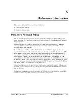
Page 109: ...s actual and current owner This requires a sales receipt showing the unit serial number and owner s name or a written statement from the owner attesting that he or she is the owner of the unit The statement can be a fax copy of the document The fact that the unit is in the hands of an HP representative on behalf of the customer is not evidence of ownership In addition HP will not remove the passwo...

Page 110: ... Windows or in some other application or combination of applications you should make the determination under those same applications Self test is not a normal operating condition and is not a sufficient tool for interpreting display quality 2 Use the table below to determine whether the display should be considered for replacement These are the only conditions in this guideline that may call for a...

Page 111: ...ltiple defective dots within 15 mm Mechanical Imperfections Discoloration Polarizer bubbles dents b Any polarizer bubble discoloration or dent that is visible from at least 36 cm 14 in Definitions of imperfections a Bright or dark dot a subpixel red green or blue dot that is stuck on or off b Polarizer dent or bubble a light spot with a darker border that appears on a lighted display and does not ...

Page 112: ... 0950 3831 Hard disk drive 10GB 9 5mm IBM See Table 4 1 on page 4 3 0950 3832 Hard disk drive 5GB 9 5mm IBM See Table 4 1 on page 4 3 0950 3906 Hard disk drive 10 5GB 9 5mm FUJ See Table 4 1 on page 4 3 0950 3935 Hard disk drive 20GB 9 5mm IBM DJSA 220 See Table 4 1 on page 4 3 0950 3967 Hard disk drive 18 0GB 9 5mm IBM See Table 4 1 on page 4 3 F1320 60971 5182 5138 Trackpoint Cap Bag of 5 F2009 ...

Page 113: ......

Page 114: ...Part Number F3257 90025 Printed in U S A 6 01 ...

Reviews: