


4-3
Replacing Components
Replacing Power Supplies
Re
pla
c
in
g Co
mpo
nent
s
3.
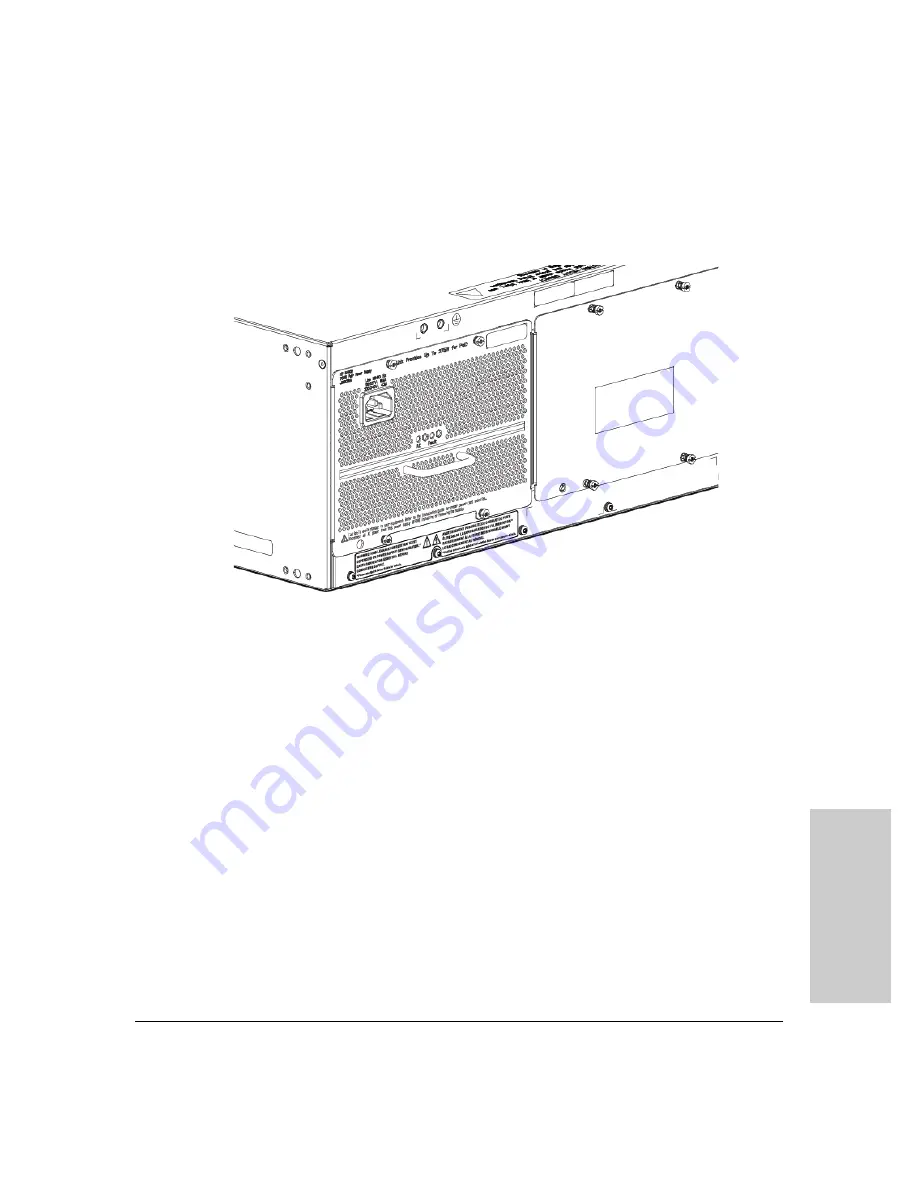
Insert the power supply into the opening. Slide it all the way in until it
connects to the switch. The power supply face plate will be flush with the
back face of the switch.
Figure 4-2. Power supply installation
4.
Tighten the four retaining screws that hold it in place. Be careful not to
overtighten the screws.
For more details, see the
HP
Switch zl2 Internal Power Supply Installation
Guide
.
Summary of Contents for 5400R zl2 Series
Page 1: ...HP 5400R zl2 Switches Installation and Getting Started Guide Power over Ethernet ...
Page 2: ......
Page 3: ...HP 5400R zl2 Switches Installation and Getting Started Guide ...
Page 10: ......
Page 78: ...4 8 Replacing Components Replacing the Management Module SD Card Replacing Components ...
Page 94: ...5 16 Troubleshooting HP Customer Support Services Troubleshooting ...
Page 100: ...A 6 Specifications Specifications ...
Page 138: ...6 Index Index ...
Page 139: ......


