


2-20
Installing the HP 5400R zl2 Switches
Installation Procedures
Ins
talling the HP 5400R zl2
S
w
itch
e
s
N o t e
Use only the included 6 mm/0.24 inch flat head screws. Using any of the 8 mm/
0.31 inch screw included in other rack mounting kits interferes with internal
components.
6.
Rest the switch on the two half-way installed screws and secure the
switch to the rack using the top hole in each Rack Mount Bracket.
7.
Align each Cable Manager such that two holes in the Cable Manager align
with two empty holes in the Rack Mount Bracket and secure with two
screws.
8.
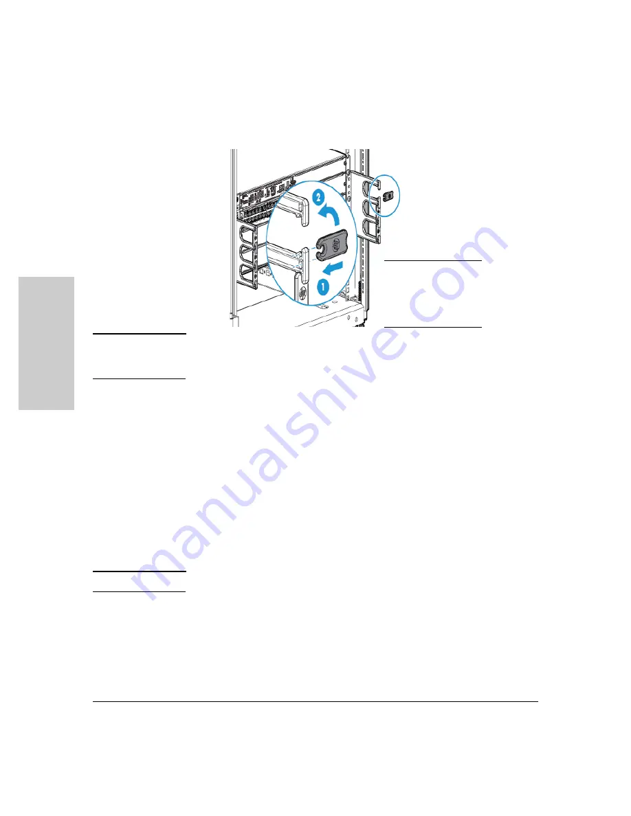
Snap the Cable Retainers into the arms of the Cable Managers.
Horizontal Surface Mounting
Place the switch on a table or other horizontal surface. Use a sturdy surface
in an uncluttered area. You may want to secure the networking cables and
switch power cord to the table legs or other part of the surface structure to
help prevent people from tripping over the cords.
N o t e
Ensure the air flow is not restricted around the sides and back of the switch.
6. Install the Grounding Wire
If a grounding wire is to be attached to the switch chassis, the grounding lug
must be removed and a wire crimped to it and the grounding lug must be
reinstalled.
1.
Use a Torx T25 driver and remove the grounding lug and two screws from
the back of the switch.
1
Install the retainer
horizontally
2
Rotate the retainer
to the vertical
position
Summary of Contents for 5400R zl2 Series
Page 1: ...HP 5400R zl2 Switches Installation and Getting Started Guide Power over Ethernet ...
Page 2: ......
Page 3: ...HP 5400R zl2 Switches Installation and Getting Started Guide ...
Page 10: ......
Page 78: ...4 8 Replacing Components Replacing the Management Module SD Card Replacing Components ...
Page 94: ...5 16 Troubleshooting HP Customer Support Services Troubleshooting ...
Page 100: ...A 6 Specifications Specifications ...
Page 138: ...6 Index Index ...
Page 139: ......


