background image

 HP Vectra XU PC – Setting Up

Installing Accessories  

••

  28

Installing Accessory Boards

Plug and Play for ISA Boards

Your PC supports Plug and Play, through the ISA Configuration Utility and the Configuration
Manager driver in CONFIG.SYS.

The ISA Configuration Utility defines the PC's configuration, which is used by the
Configuration Manager driver to determine available resources.

When you start your PC, the Configuration Manager automatically detects and configures
ISA Plug and Play accessory boards with available resources (IRQs, DMAs, memory
ranges, and I/O addresses).

You can also use the ISA Configuration Utility if you are installing non-Plug and Play
accessory boards. The ISA Configuration Utility will determine the recommended settings for
each ISA non-Plug and Play board you want to install.

These settings may be different from those recommended by the board's manufacturer. In
this case, the board's jumper settings and driver options (in CONFIG.SYS) must be altered.

If you have any problems using ISA Plug and Play accessory boards, first run the ISA
Configuration Utility and check it correctly defines the PC's configuration.

NOTE

Any changes you make using the PC's SETUP program are not automatically
detected by the ISA Configuration Utility. Therefore, after making any changes in
SETUP, you must run the ISA Configuration Utility to update the changes made to
the PC's configuration.

For further information, open the 

Plug and Play

 group in the Windows 

Program Manager

.

Click on the 

ISA Configuration Utility

 icon. This will display a Readme file.

Summary of Contents for 5/xx

Page 1: ...HP Vectra XU PC Setting Up In This Manual 1 Setting Up Your HP Vulcan XU PC Introduction ...

Page 2: ... Switches Replacing the Power Supply Installing Accessory Boards Video Adapter Upgrading the Matrox Video Adapter Board Memory VESA Pass through Connector Replacing the Cover Completing the Installation Procedure Configuring Your PC Overview Starting SETUP Using SETUP to Configure the PC Setting the Date and Time and User Preferences Viewing Processor and Main Memory Information Configuring the Di...

Page 3: ...Disk Does Not Work If a SCSI Device Does Not Work If all SCSI Devices Stop Working If the Hard Disk Activity Light Does Not Work If the Keyboard or Mouse Does Not Work If the Printer Does Not Work If an Accessory Board Does Not Work Other Problems If Your Application Software Does Not Work If You Forget the Passwords If You Can t Start SETUP If You Can t Change the PC s Configuration in SETUP If t...

Page 4: ...lains how to configure the PC for the hardware accessories you installed Using HP Utilities and HP User Tools explains how to use HP Utilities and HP User Tools Troubleshooting and Error Messages explains how to correct any problems with the PC Technical Information provides technical information Index gives an alphabetical list of the information in this manual NOTE If you need more information o...

Page 5: ...de for Matrox Video Adapter board Only for models that are supplied with a Matrox Video Adapter For information on product numbers and other supported accessories refer to the product datasheet When installing accessories You will need a medium tip flat blade screwdriver The tip should be 6 mm wide Keep any parts you remove from the PC in a safe place in case you need to install them again later I...

Page 6: ... Utility in the Plug and Play group in Windows Refer to Installing Accessory Boards later in this chapter WARNING For your safety never remove the PC s cover without first removing the power cord and any connection to a telecommunications network Some large displays are heavier than one person can lift safely Refer to the display s documentation If in doubt never lift a large display without help ...

Page 7: ...erting from a Desktop to a Deskside Unit Your PC can be used in either a desktop or a deskside position 1 Remove the PC s cover as described earlier in this chapter 2 Change the nameplate as follows a From behind the front panel push the nameplate s stem to release the locking tabs from the cover b Turn the nameplate into its deskside position Align the key on the nameplate with the hole in the co...

Page 8: ...kside position Insert the plastic tabs into the frame Ensure the metal case around the panel is inside the frame Gently push the control panel back into place 4 Install any other accessories before replacing the cover Where to Install the Accessories Disk drives and accessory boards can be installed without moving the power supply You will need to move the power supply to install main memory or ad...

Page 9: ...in the top shelf Some models have a hard disk drive already installed The PC has four shelves for mass storage devices check with your dealer for supported devices the top shelf has a 3 5 inch slim 1 inch high 1 44 MB flexible disk drive the middle shelf can be used for any 5 25 inch half height front access device such as a flexible disk drive or CD ROM drive the bottom shelf can be used for a se...

Page 10: ...the operating system The first IDE hard disk drive you install must then be connected to the longer IDE data cable This is the Drive 1 position as defined in the SETUP program When installing an IDE device other than a hard disk drive connect it as follows use the longer IDE data cable for a device installed in the middle shelf use the shorter IDE data cable for a device installed in the lower she...

Page 11: ... address relative to other devices on the bus The optional CD ROM is slower than a hard disk but can automatically disconnect when a faster SCSI device needs to use the bus Software Installation SCSI devices are not auto detected during the Power On Self Test and MUST be configured in DOS You MUST exit Windows and enter MS DOS do not use the MS DOS prompt in Windows When in MS DOS carry out the fo...

Page 12: ...For non HP devices make sure that the terminating resistor is removed NOTE Never modify the terminating resistor at the end of the cable 3 Connect the device to any available connector on the SCSI cable Device Connector Device Connector Device Connector Terminating Resistor System Board Connector Cabling for an external SCSI device 1 Contact your dealer for HP shielded cables to connect external S...

Page 13: ...Access Device in the Middle or Bottom shelf To install a flexible disk drive or CD ROM drive 1 Remove the PC s cover as described earlier in this chapter XREF COVER 2 Unscrew and remove the filler panel from the shelf 3 Firmly slide the device into the shelf 4 Secure the device in position using the screws you removed from the filler panel ...

Page 14: ... Up Installing Accessories 14 5 Unscrew the captive screw on the hard disk drive in the rear shelf Rotate the drive out of the way for better access to the cables 6 Connect the power and data cables to the rear of the device ...

Page 15: ...fer to Installing SCSI Devices and Installing IDE Devices Flexible Drive Cable Power Cable IDE Socket SCSI Socket 7 Replace the hard disk drive in the rear shelf 8 Install any other accessories before replacing the cover Then run SETUP Refer to Configuring Your PC NOTE You can use the ShowSCSI utility to graphically display SCSI device information ...

Page 16: ...er devices you may need to install a controller board Refer to the device s manual for any special installation procedure To install a hard disk drive in the rear shelf 1 Remove the PC s cover as described earlier in this chapter 2 With the drive s label uppermost place the drive on top of the power supply towards the back 3 Align the drive with the hinges on the rear drive shelf Then insert the d...

Page 17: ...hen install the operating system if required Install any software drivers needed for the device and then any other applications Refer to Completing the Installation Procedure Installing a Hard Disk Drive in the Bottom Shelf Your PC has an integrated Fast SCSI 2 controller for SCSI drives and an integrated Enhanced IDE controller for IDE drives For other devices you may need to install a controller...

Page 18: ...retainer plate that secures the mass storage bridge to the PC Put the screw to one side 4 Firmly insert the drive into the bottom shelf until you feel resistance 5 Firmly insert the retainer plate under the disk drive tray to secure the drive Replace the screw 6 Replace the filler panel using the screws you removed 7 Unscrew the captive screw on the hard disk drive in the rear shelf Rotate the dri...

Page 19: ... IDE cable according to the drive type Make sure that you connect to the socket indicated Refer to Installing SCSI Devices and Installing IDE Devices NOTE The connectors are shaped to fit one way only 9 Replace the hard disk drive in the rear shelf If you need to replace the drive in its hinges refer to Installing a Hard Disk Drive in the Rear Shelf ...

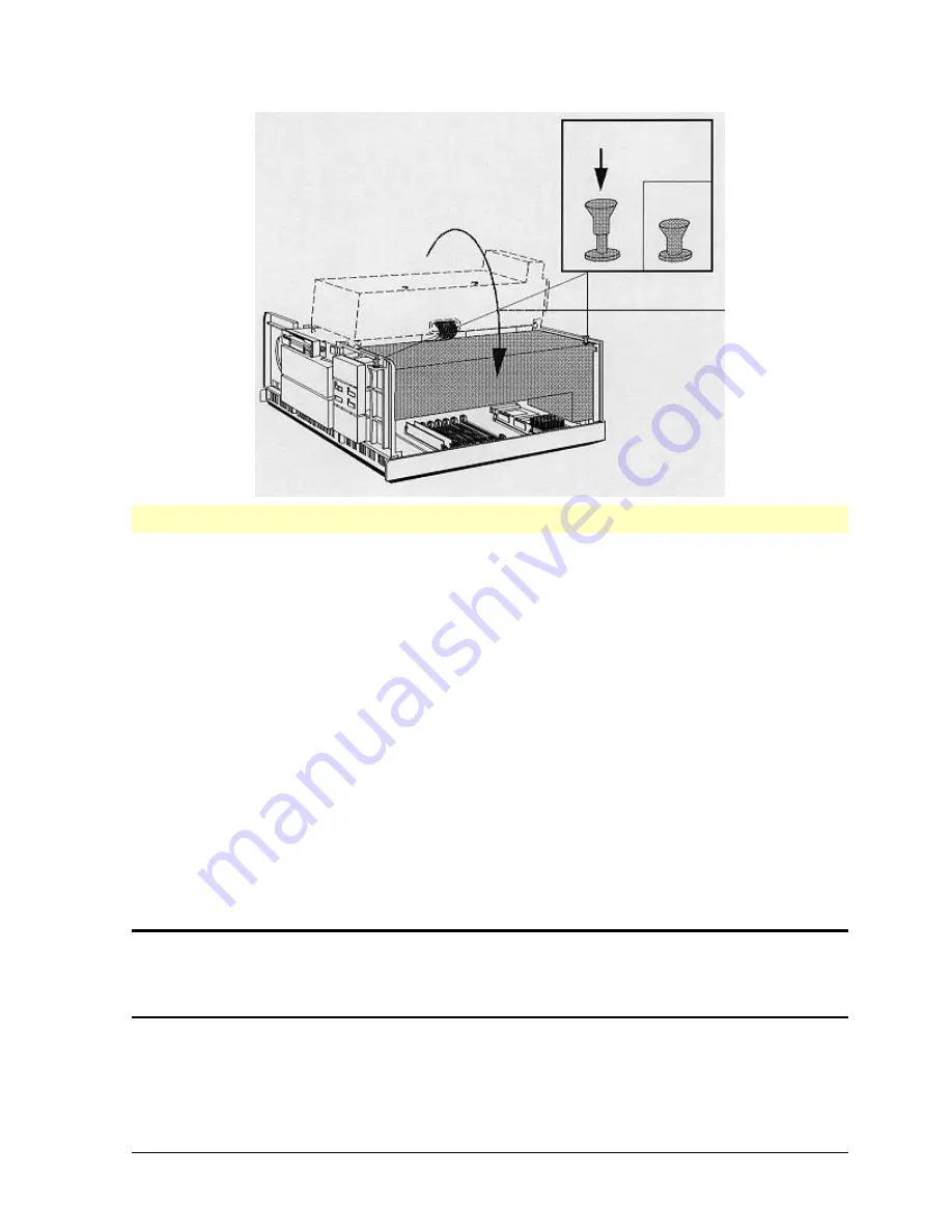
Page 20: ...eded then format this hard disk Refer to Completing the Installation Procedure at the end of this chapter Remove the Power Supply Remove the power supply to access the sockets for the main memory or processors 1 Check that you have removed the power cord from the PC 2 Remove the PC s cover as described earlier in this chapter 3 Pull up the fasteners on the power supply and rotate it onto the PC s ...

Page 21: ...ur banks labeled A to D There are two sockets in each bank Memory modules can be installed up to a maximum of 256 MB CAUTION Static electricity can damage electronic components Turn all equipment OFF Avoid wearing wool or polyester and don t let your clothes touch the accessory To equalize the static electricity rest the accessory bag on top of the power ...

Page 22: ...e installed in pairs of the same capacity beginning with bank A up to bank D 3 Align the main memory module directly over the socket with the cutout towards the outside of the PC Slide the memory module into the socket at 45 Firmly press the memory module completely into the socket 4 Pivot the memory module to the vertical position 5 Repeat this procedure for the other memory modules 6 Install any...

Page 23: ...ipment OFF Avoid wearing wool or polyester and don t let your clothes touch the accessory To equalize the static electricity rest the accessory bag on top of the power supply while you are removing the accessory from the bag Handle the accessory as little as possible and with care To install a dual Pentium processor A second Pentium is supported only by certain advanced operating systems Windows N...

Page 24: ...N and replace it to connect pins 1 2 together OFF 7 Install any other accessories before replacing the power supply and the cover Then run SETUP Refer to Configuring Your PC To upgrade the existing Pentium processor for a faster one 1 Remove the PC s cover and power supply as described earlier in this chapter 2 Unlock the ZIF socket containing the existing Pentium processor by raising the locking ...

Page 25: ...eated correctly do NOT press it into the socket Lift it out and try again 6 Lower the ZIF socket lever to lock the processor into place 7 Put the processor you took out of the PC in the packaging provided with the new processor Keep this in a safe place for possible future use 8 Set the system board switches to the appropriate settings as described in the following pages To install an OverDrive fo...

Page 26: ...rectly do NOT press it into the socket Lift it out and try again 5 Lower the ZIF socket lever to lock the processor into place 6 Unlock the ZIF socket containing the existing Pentium processor by raising the locking lever 7 Remove the existing processor and put in the packaging provided with the new processor Keep it in a safe place for possible future use 8 Set the system board switches as descri...

Page 27: ... 40 60 OFF ON ON 66 66 100 ON OFF OFF 60 120 ON OFF ON 50 100 ON ON OFF 40 80 ON OFF ON 66 66 133 Subject to change Refer to the upgrade processor documentation Switch 1 sets the processor s external internal bus speed ratio The default setting is OFF 2 3 ON sets the ratio to 1 2 Replacing the Power Supply Replace the power supply after you have finished installing main memory or an upgrade proces...

Page 28: ...SA Configuration Utility will determine the recommended settings for each ISA non Plug and Play board you want to install These settings may be different from those recommended by the board s manufacturer In this case the board s jumper settings and driver options in CONFIG SYS must be altered If you have any problems using ISA Plug and Play accessory boards first run the ISA Configuration Utility...

Page 29: ...or either a full length 32 bit PCI or 16 bit ISA board Slot 5 can be used for a half length 32 bit PCI board If your PC has a Matrox video adapter board it is usually located in slot 4 the combination PCI ISA slot To install an accessory board ISA or PCI 1 Before you install an ISA accessory board run the ISA Configuration Utility in the Plug and Play group in Windows a Check that the board s IRQ ...

Page 30: ... the board guide of the chosen slot Do not bend the board If you install a full length board ensure the board correctly engages with the board guide and clip at the end of the slot 6 Align the board s connector with the slot s socket Firmly press the board into the socket Ensure the board s connector engages completely with the socket and does not touch components on other boards 7 Secure the boar...

Page 31: ...Adapter on the System Board If your PC has an integrated Ultra VGA PCI video controller on the system board it has 2 MB of video memory and can display high resolutions at high refresh rates It can display 16 7 million colors at 800 x 600 pixels 64 thousand colors at 1024 x 768 pixels 256 colors at 1280 x 1024 pixels Refer to Some of the Available Video Resolutions for details of more of the resol...

Page 32: ...z Refer to Some of the Available Video Resolutions at the beginning of Technical Information for more details of the resolutions CAUTION Static electricity can damage electronic components Turn all equipment OFF Avoid wearing wool or polyester and don t let your clothes touch the accessory To equalize the static electricity rest the accessory bag on top of the power supply while you are removing t...

Page 33: ...omponents on other boards which may be installed 8 Secure the board by replacing the screw 9 Install any other accessories before replacing the cover VESA Pass through Connector If you add an optional video adapter board connect the board s ribbon cable to the VESA pass through connector on your PC The cable and connector must be connected pin 1 to pin 1 which are marked Refer to your video adapte...

Page 34: ... Matrox Dual Screen Mode Dual screen mode allows you to use two displays at the same time For this you need two identical Matrox boards Connect each display to a Matrox board Refer to the manual supplied with your Matrox board if you need further information Replacing the Cover 1 Ensure you have installed all your accessories 2 Ensure all internal cables are properly connected and safely and neatl...

Page 35: ...un SETUP Refer to Configuring Your PC Completing the Installation Procedure If you installed After installing you need to 5 25 inch flexible disk drive Run SETUP and check the drive is detected If required select the Bootable Drive SCSI device including CD ROM drive Run SETUP and check the SCSIIntegrated Interface is enabled If you have at least one SCSI hard disk drive installed check that theSCS...

Page 36: ...ing Your PC In Windows double click on the relevantReadme icon in the Hputils group in the Program Manager Follow the instructions on how to install the software drivers For an IDE drive run SETUP and check the IDE Integrated Interface is enabled and the drive is detected Refer to Configuring Your PC Format the drive referring to the manuals for your operating system Main memory Run SETUP and chec...

Page 37: ... and Serial Ports Network Video Modes IRQ Map for Accessory Boards BIOS Version SETUP has three types of entries entries filled automatically when the PC detects hardware during the Power On Self Test POST entries providing information only which cannot be changed entries you can set to your own values for example passwords NOTE If you can t change the PC s configuration in SETUP The System Admini...

Page 38: ...ower On Self Test If you miss the message press and hold the RESET button to restart the PC and try again 3 Follow any screen instructions enter your password if you have one The SETUP Menu will appear The information displayed on your screen may be different Using SETUP to Configure the PC Check the configuration when you first use the PC and each time after you install remove or upgrade any acce...

Page 39: ...ting the Date and Time Use these fields to set the PC s date and time for your applications Setting Your User Password Set a User Password to prevent your PC being started in your absence use the Keyboard Lock Button IC LOCK to lock your PC use the Keyboard Lock Timer when enabled to lock your PC use Screen Blanking when enabled to conceal your data This feature is not available if your PC has a M...

Page 40: ...ith a User Password set Screen Blankingconceals your data on the screen if you lock the PC using the Keyboard Lock Button or Keyboard Lock Timer You can only use Screen Blankingif your PC has an integrated Ultra VGA PCI video controller To set or change Screen Blanking 1 Press to go to the Screen Blankingline 2 Press F8 to change the line to Screen BlankingEnabled Setting Your Keyboard Preferences...

Page 41: ... memory mapped between 1 MB and 15 5 MB Specify the board s available Linear Frame Buffer LFB memory Refer to the board s manual for details Memory Hole Below 1 MB Use this field for ISA accessory boards with memory mapped below 1 MB Specify the board s memory and its location in main memory between 0C8000 h and 0DFFFF h Refer to the board s manual for details Setting the 15 MB Limit for Extended ...

Page 42: ... installed an optional SCSI hard disk drive configure it in SETUP To configure an IDE hard disk drive 1 If your PC has no IDE hard disk drives in the IDE Hard Disk Drives Interface section both the Drive 1 and Drive 2 fields will be set to None or SCSI 2 If your PC has one IDE hard disk drive already installed check that the Drive 1 field is set to Configured and the Drive 2 field is set to None o...

Page 43: ...rive is not detected there may be a hardware problem If the drive uses the integrated IDE interface check that the interface is enabled If the drive is detected during the Power On Self Test but you cannot access it you should enter the details of the drive which are displayed in the SETUP program You cannot enter the drive s details if they are not displayed by the SETUP program Refer to the sect...

Page 44: ... be used to start the PC from a network server Refer to Configuring the Network Interface Disabling the flexible disk drive to prevent application software and operating system files being copied to or from the PC s mass storage devices Disabling the IDE and SCSI integrated interfaces to prevent application software and operating system files being copied to or from the PC s mass storage devices D...

Page 45: ... to switch the ports Off Set the parallel port to Parallel 1 IRQ 7 Parallel 2 IRQ 5 or Off Set the Parallel Port Mode to Centronics for transmitting data bidirectional ECP mode or bidirectional EPP mode for transmitting and receiving data If the device has an ECP EPP interface make sure you use a compatible cable order C2950A IEEE 1284 B standard connector or C2945A IEEE 1284 C small connector Mak...

Page 46: ...in circumstances you may be asked to insert a LAN Driver diskette in drive A In this case you should either use the LAN driver diskette which you created with the Master Diskette Creation Utility or you should type C MASTERS LANDRV DISK1 Enabling Remote Program Load The Remote Program Loadgroup of fields enable the PC to start from a server The Remote Start field allows you either to disable Remot...

Page 47: ...tart automatically after a power failure and restart the network software without a password Network security is maintained because the keyboard remains locked until a User Password is entered Configuring Accessory Boards IRQ Map for Accessory Boards If you have installed an ISA accessory board that uses IRQ 9 10 11 or 15 you must tell SETUP which IRQ it uses This allows PCI devices to be configur...

Page 48: ...ure the board Refer to Configuring the Matrox Video Adapter Board later in this chapter Configuring the VGA Enhanced Ergonomic Modes The VGA Enhanced Ergonomic Modesfields allow you to select the integrated video adapter s refresh rates This may be necessary for applications such as Windows Autocad or Microstation To minimize display flicker select the highest refresh rate supported by your displa...

Page 49: ...de all your changes you must save them and exit SETUP 1 Press F3 to save the changes 2 Follow the instructions on the screen to exit SETUP Your PC automatically restarts If you have set a User Password the User Password prompt is displayed Type your User Password and press ENTER NOTE After making any changes in SETUP run the ISA Configuration Utility in the Plug and Play group in Windows This upda...

Page 50: ... by your display your PC has enough Video Memory for the resolution you choose the refresh rate for the selected resolution chosen in PC Setup is supported by your display Under certain circumstances you may be asked to insert a diskette in drive A In this case you should either use the diskette which you created with the Master Disk Creation Utility or type C MASTERS VIDDRV DISKWINin place of A C...

Page 51: ...creen Using the Matrox Video Software Tools The MGA Control Panel icon in the bottom left hand corner of your display provides access to the Matrox Video Software Tools The MGA Control Panel Double clicking on the MGA Control Panel icon allows you to change the display resolution and color depth select large or small display fonts make the Windows desktop area larger than the screen area select zo...

Page 52: ...3D Studio 2 0 and 3 0 providing high resolution customizable menus and pop up windows It runs in Protected mode is fully compatible with ADI 4 2 and features Up to 1600 x 1200 resolution List based operation for faster AutoCAD redraws and zooms The Dyna View windowing environment which includes A movable resizable AutoCAD graphic window A pinnable overlay text window User defined iconized menus Di...

Page 53: ...e video resolution Set up your printer and plotter Change your User Name Read the License Agreement Read the Working in Comfort document To access HP User Tools 1 Click on the HPUtils group icon in Program Manager to display Hewlett Packard Utilities 2 Click on the HP User tools icon to display the HP User Tools utility Your screen will be similar to the one illustrated below 3 Click on the icon o...

Page 54: ...pre loaded software You can configure your HP Vectra XU PC using the utilities supplied in the HPUtils Group in Windows Some of these are mentioned below The Master Diskette Creation Utility This utility is used to create master copies of the software supplied on the hard disk We recommend that you use new diskettes Diskettes which have been used previously may have sectors which are corrupt and t...

Page 55: ...ot work if a hard disk does not work if a SCSI device does not work if all SCSI devices stop working if the keyboard or mouse do not work if the printer does not work if an accessory board does not work If you have other problems if you have software problems if you forget the passwords if you can t start SETUP if the date and time are incorrect if you have problems running your backup programs If...

Page 56: ...Information and Using the Matrox Video Software Tools in Configuring Your PC If a high resolution display shows spurious colors 1 Make sure the Red Green and Blue lines are connected to their corresponding inputs on the display 2 Make sure your display s RGB inputs are set to 75 ohms 3 The video settings may not be correct for the display If your PC has an integrated video adapter on the system bo...

Page 57: ... Installing Accessories for details d Check the processor is correctly installed Refer to Installing Accessories for details e Check that accessory boards are firmly seated in their slots Refer to Installing Accessories for details f Verify that any switches and jumpers on the accessory boards are properly set Refer to the manuals that came with each board g Check the switches on the system board ...

Page 58: ...button and follow the instructions until the procedure finishes CAUTION Do not switch OFF the PC until the ROM update procedure has completed successfully or not since irrecoverable damage to the ROM may occur 4 Remove the HPROMInit utility diskette 5 Switch the PC OFF and then back ON to initialize the system ROM If a POST Error Message Appears You can stop the memory test and jump to the next te...

Page 59: ...em board switch CONFG being set to ON refer to Troubleshooting and Error Messages for details 2 If the hardware has been changed run SETUP to update the configuration information Note that SETUP automatically fixes most errors 3 If the problem persists contact your authorized HP service representative 0801 1 If you don t start boot your PC remotely run SETUP Set Remote Start to None and set Protoc...

Page 60: ...y alphanumeric key to continue Missing operating system Explanation You tried to start the PC but the PC could not find the operating system Corrective Action s Run SETUP and make sure the hard disk has been correctly configured Cannot start from hard disk Explanation Your IDE hard disk drive is incorrectly configured in SETUP Corrective Action s Run SETUP and go to the IDE Hard Disk Drives Interf...

Page 61: ...y asterisks will be displayed explaining what failed during this stage HP PC LAN card hardware failure Explanation The network interface failed Contact your HP dealer for assistance HP PC LAN Card PROM corrupted Explanation Every network adapter has a unique identification number the MAC Address burned in a PROM This message will appear if the PC detects a MAC Address checksum error Contact your H...

Page 62: ...Hard Disk Does Not Work 1 Check the hard disk drive has not been disabled in SETUP Refer to Configuring Your PC for details 2 Check the disk power and data cables are correctly connected Refer to Installing Accessories for details 3 If it is a SCSI hard disk drive refer to the section If a SCSI Device Does Not Work If an IDE Hard Disk Does Not Work 1 If you install an IDE hard disk drive in a PC w...

Page 63: ...mage For proper operation the length of the SCSI cabling should not exceed 6 meters 19 feet 8 inches The internal SCSI cable is 1 meter 3 feet 3 inches in length therefore your external bus is limited to 5 meters 16 feet 5 inches 6 If there are no system error messages check each SCSI component However equipment failure is the least likely problem If the Hard Disk Activity Light Does Not Work If t...

Page 64: ... printer is configured correctly for the PC and for the application a Make sure the PC s port has been correctly configured using SETUP b Make sure the printer is correctly set up In Windows double click on the Printer button in HP User Tools Note that all printer drivers are in the directory C WINDOWS OPTIONS If you are asked to install a diskette in drive A when installing a printer you should r...

Page 65: ... Off in SETUP Refer to Configuring Your PC Memory Cache copies a portion of the PC s memory into very high speed memory or cache This allows the processor to access frequently used pieces of information more quickly 3 If Windows does not run properly refer to the Windows manual for guidance 4 If the network connection does not work properly contact your Network Administrator 5 If you have changed ...

Page 66: ...ils 2 Set system board switch CONFG to ON Refer to Troubleshooting and Error Messages for details 3 Switch ON the PC to erase the memory 4 Check that error messages 0240 and 02C0 are displayed and wait until the PC has started booted 5 Switch OFF the PC 6 Set system board switch CONFG to OFF Refer to Troubleshooting and Error Messages for details 7 Replace the cover Refer to Installing Accessories...

Page 67: ...e the SYSTEM INI file as an ASCII file 4 To avoid compatibility problems open the Windows Control Panel a Select 386Enhanced b Choose Virtual Memory c Choose Change d Set Use 32 bit File Access to OFF no cross in box e Select OK 5 When you have done this restart Windows to activate the drivers Getting Support This section explains how and where to get technical answers and support for your PC Hewl...

Page 68: ...n the world who has access to the Internet or access to World Wide Web through a hypermedia viewer Internet IP Address 192 6 71 2 Alias ftp boi external hp com Name anonymous Password Enter your E mail address World Wide Web URL http www hp com home html HP Forum on CompuServe The HP Systems Forum on CompuServe is an on line service accessible via modem This service provides information about your...

Page 69: ...our hardware warranty This service will provide technical assistance with basic configuration and setup of your Vectra PC To ensure that your enquiry is dealt with quickly have the following information ready when you call HP your HP Vectra model number and serial number the operating system version and the configuration a description of the software installed and the accessories used For more det...

Page 70: ...dqtrs Hewlett Packard S A 7 Rue du Bois du Lan P O Box 364 CH 1217 Meyrin 1 Geneva Switzerland CANADA Hewlett Packard LTD 6877 Goreway Drive Mississauga Ontario L4V 1M8 Canada Recycling Your PC HP has a strong commitment toward the environment Your HP Personal Computer has been designed to respect the environment as much as possible HP can also take your old PC back for recycling when it reaches t...

Page 71: ...eo memory size speed Some models have an integrated Ultra VGA PCI video controller with 2 MB of video memory Some models have a Matrox video adapter board with 2 MB of video memory which can be upgraded to 4 MB Refer to Some of the Available Video Resolutionstables later in this chapter for details Rear Connectors 6 pin mini DIN keyboard 6 pin mini DIN mouse 25 pin ECP EPP bidirectional parallel 9...

Page 72: ...her a front access drive or a hard disk drive HP Keyboard and Mouse With mini DIN connectors Characteristics Weight 11 kilograms 24 pounds Dimensions 41 cm D by 44 cm W by 17 cm H 16 1 inches by 17 1 inches by 6 6 inches Footprint 0 18 m sq 2 1 sq ft Storage temperature 40 C to 70 C 40 F to 158 F Storage humidity 8 to 80 relative Operating temperature 5 C to 40 C 41 F to 104 F Operating humidity 1...

Page 73: ...SETUP DMA 2 flexible disk drive controller DMA 3 available DMA 4 used to cascade DMA channels 0 3 DMA 5 available DMA 6 available DMA 7 available I O addresses 1F0 h 1F7 h integrated flexible disk drive controller 278 h 27F h parallel port 2 2E8 h 2EF h serial port 4 if enabled in SETUP 2F8 h 2FF h serial port 2 if enabled in SETUP 3B0 h 3DF h integrated video controller on certain models only 378...

Page 74: ...0 x 600 2 MB 120 Hz 1024 x 768 2 MB 120 Hz 4 MB 76 Hz 1152 x 882 2 MB 100 Hz 4 MB 60 Hz 1280 x 1024 2 MB 90 Hz 4 MB 90 Hz Not Available 1600 x 1200 2 MB 66 Hz 4 MB 66 Hz Not Available bpp bits per pixel For information on video drivers click on the Readme file in the Hputils group in Windows Program Manager The PC s Memory Map Memory Area Memory Range Hexadecimal Address Range Used by Extended Mem...

Page 75: ... connector for connecting IDE hard disk drives A Fast SCSI 2 connector for connecting SCSI devices A VESA pass through connector only on models that have an integrated video controller on the system board The VESA pass through connector can be connected to an optional video adapter board that uses the integrated video controller Using Your PC s System Board Switches To change the switch settings 1...

Page 76: ...de Security mode prevents changes to the PC s configuration using the PC s SETUP program OFF to disable security mode ON to enable security mode Switch ON if you don t want anyone to change the PC s configuration 4 CONFG Retain or clear the configuration stored in EEPROM OFF to retain configuration ON to clear configuration Switch ON if you need to clear the PC s configuration information for exam...

Page 77: ...nical Information 77 ON OFF ON 66 66 133 Subject to change Refer to upgrade processor documentation Switch 1 sets the external internal bus speed ratio The default setting is OFF 2 3 ON sets the ratio to 1 2 The PC s Rear Connectors ...

Reviews: