background image

For more information visit:

www.hornby.com

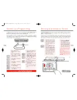
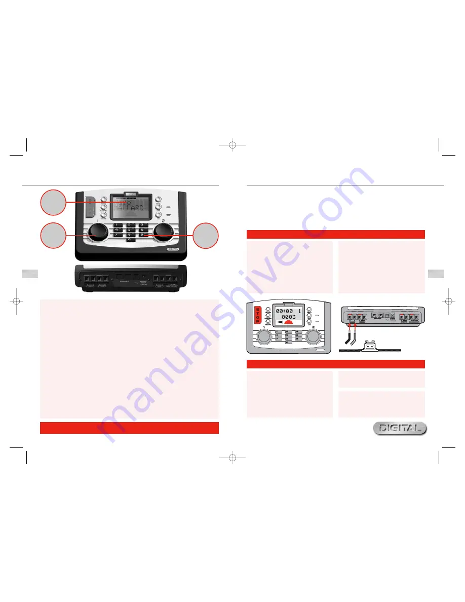
Connecting the Elite Unit to the Track

1.

Locate the terminals at the back of the 

Elite

unit

labelled 

TRACK

. See Fig 1 

2.

Locate the Track to the Controller Link Wire

and insert the black lead into Socket 

A

and the

black and white lead into Socket 

B

.

(These wires must NOT be inserted into mains

socket outlets.)

3.

If fitted, locate the Hornby Power Input Track

section on the track circuit.

4.

Press down on the left hand button on the Power

Input Track section and insert the black and white

lead of the Link Wire into the socket and release

the button.

5.

Repeat the process inserting the black lead into

the right socket of the Power Input Track.

Connecting the Power Supply 

1.

Locate the Power Transformer with integral

cable.

2.

Locate the Power Input socket on the rear of

the unit (

POWER +15V DC

)

3.

Take the Power Supply cable and insert the plug

into the Power Input socket situated at the rear

of the 

Elite

unit.

4.

Plug the Power Transformer into the mains socket

and switch on the power.
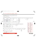
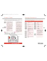
Keyboard

The 17 button keyboard includes not only buttons 0 – 9
keys which are alpha numeric, but other keys marked

Locomotive

,

Accessory

,

Function

,

On/Off

,

Menu

,

Escape

and of course 

Stop

! These  multi-function  keys

provide the basis for the programming and functioning of
up to 254 locomotives and 255 accessories including points.
The keyboard has the capability of entering into the unit’s
memory the names and numbers of locomotives and
accessories as well as inputting the various functions that
the Hornby Elite offers. Using the Elite’s keypad locomotives
can be addressed from 0 to 9999 and points or solenoid
operated accessories from 1 – 252 if assigned to a Hornby
R8216 Accessory/Points  Decoder.

Rotary Control

The Hornby Elite Digital Unit incorporates two rotary
controllers which not only control the assigned locomotives
but also assist in registering each model and accessory to
the Elite.The controls are able to do this by a simple click
and rotate procedure.

This method is also employed to add names and locomotive
numbers to the Elite display so that in place of locomotives
being identified with just their coded number, abbreviated
names and /or running numbers can be used. The pressing

of the Rotary Controls can also determine which knob has
control, the direction of the locomotive’s travel plus point
motor activation.These are just a few of the functions that
are associated with the Rotary Controls, however they do
go some way to illustrate the technical advances that the
Hornby Digital Elite boasts.

LCD Display

The liquid crystal display centred on the Elite has 2 rows
of 8 characters, train direction indicators, a speed indicator,
and a set of 13 numbers which are 0 – 12 which show the
functions that are switched on in respect of locomotives
under direct control.

A clock is also included on the display which can be set to
real time or can be set up to 10X faster. Working with the
Rotary Controls the display will be able to keep the operator
fully up to date with the functionings of the Elite.

Power

The Elite is supplied with a 4 amp transformer. 3 amps is
passed directly to the tracks and 1amp is for the Accessories,
thus the Elite is capable of providing enough power to run
at any one time approximately 10 locomotives depending
on how power efficient the locomotives are.

If the Elite is being connected to an existing layout it must be noted that for Digital Control (DCC) to operate

at its full potential it is important that the locomotives receive a strong and consistent signal from the Elite.

Please ensure the track and connecting fishplates are clean and are firmly connected.

The Hornby Elite unit operates most efficiently when the whole of the layout is “live”. Hornby points are self

isolating therefore it is necessary to fit each point with 2 x 

R8232 Hornby DCC Electric Point Clips

.

See page 8 for further information.
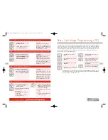
Setting Up

4

5

Elite Unit – Fact File

Keyboard

Rotary

Control

LCD

Display

Rotary

Control

LCD

Display

Keyboard

Fig 1

4

Please Note:

There is no On/Off switch on the 

Elite

unit.

Always ensure that the power supply is disconnected

from the 

Elite

when not in use.

Elite HBook updated 6.3.07_Q6.qxd  13/3/07  13:09  Page 2

Summary of Contents for 'Elite" Unit

Page 1: ...Elite Unit Operator s Manual Hornby Hobbies Limited Margate Kent CT9 4JX Tel 44 0 1843 233525 For more information visit www hornby com M00000 Elite HBook Cover Section 13 3 07 13 07 Page 1...

Page 2: ...g will work The Hornby Elite Digital Control has the ability to address 254 locomotives and depending on the accessory point decoders used up to 255 points or solenoid operated accessories The followi...

Page 3: ...22 Changing Locomotive Direction 23 Setting Up the Elite 24 Clock Setting 26 Loco Log or Search Function 27 Alternative Programming Modes 28 Locomotive Favourite Setting 29 Advanced Locomotive Program...

Page 4: ...s method is also employed to add names and locomotive numbers to the Elite display so that in place of locomotives being identified with just their coded number abbreviated names and or running number...

Page 5: ...h German Reset Confirm Acc Unit Gp Create Gp Adr Adr 0003 Loco1 Adr 0001 Loco2 Adr 0002 Gp Dissolve Gp Adr 0003 Dissolved Dbl Hdr Access the menu options by pressing the Menu button on the Elite Unit...

Page 6: ...able from Hornby stockists Making Points Live Please Note Always use Hornby Point Motors with Hornby points All new factory fitted digital locomotives are programmed No 3 as standard default During th...

Page 7: ...nu button on the Elite Screen shows Loco 4 Press Control 1 to confirm Screen shows Direct 5 Press Control 1 to confirm Screen shows Address 6 Press Control 1 to confirm Screen shows Address Write 7 Pr...

Page 8: ...rammed 7 Press Loco Screen shows Contr 2 Adr 0010 See Fig 1 8 Rotate Control 2 until the locomotive required is shown For this example 20 has been selected 9 Press Control 2 Screen shows 00 00 2 0020...

Page 9: ...programmed to each locomotive For this example No 3 locomotive will be used Before programming place the locomotive on the Programming Track Before programming the deceleration level ensure the locom...

Page 10: ...ng procedure For this example Locos 1 and 2 will be consisted as No 10 Double Head programming can be done while both locomotives are on the main circuit Please Note For both locomotives to operate in...

Page 11: ...ch off the function press the Function key then the function number and finally confirm by pressing and releasing Control 2 10 Alternatively to switch off the last function selected press the On Off b...

Page 12: ...h locomotive s movements Speed Step Change 1 Press Menu Screen shows Loco 2 Press Control 1 Screen shows Direct 3 Rotate Control 1until screen shows Features Press Control 1 4 Screen shows Features Ad...

Page 13: ...n 0 2 Press and release the selected control knob 3 Loco 0 can now be controlled 4 Rotate the selected control knob Loco 0 will move forward Press and release the selected control knob and the locomot...

Page 14: ...to the controller such as speed and details on the load that is being pulled This and much more will be available in the future At the time of writing these instructions the operating protocol for Ra...

Page 15: ...d the minutes will flash 7 Rotate Control 1 to the minutes required and press to confirm Screen shows Set Clk 8 If the hour setting is incorrect rotate Control 2 anti clockwise until the hours flash a...

Page 16: ...ive press Menu Screen shows 00 00 1 0003 or the locomotive that was programmed Using the Locomotive Favourites Setting 1 Press Menu Screen shows Loco 2 Rotate Control 1 until screen shows Unit 3 Press...

Page 17: ...having the pantograph furthest away These are general guides but are not necessarily absolute After assigning an address to a locomotive it may not move in the direction indicated by the arrow shown o...

Page 18: ...creen shows Address Short Rotate Control 1 until screen shows Address Extended Please Note A Short Addressed locomotive uses CV1 as addresses from 1 127 An Extended Addressed locomotive uses CV17 CV18...

Page 19: ...articular to the locomotive you wish to programme showing how you see the speed curve progressing This can be achieved by using graph paper and breaking each CV value into 255 segments Once this has b...

Page 20: ...o do this is as follows As an example the Acceleration CV CV3 will be adjusted Changing CVs on the Main Line 1 Press Menu Screen shows Loco 2 Press Control 1 Screen shows Direct 3 Press Control 1 Scre...

Page 21: ...f Programming Numbers 1 Press Menu and rotate Control 1 until Acc is displayed 2 Press Control 1 to confirm Screen shows Direct 3 Rotate Control 1 until Reg is shown and press Control 1 to confirm Scr...

Page 22: ...te Control to confirm 4 Press and release the selected control knob Accessory point will change direction together with the arrow symbol on the screen Using the Elite it is possible to name all access...

Page 23: ...original factory settings by utilising the Reset function Reset 43 For more information visit www hornby com 42 Overload Safety Cut Off Should there be a short circuit or an overload the Elite unit w...

Page 24: ...he accepted standards have been laid down by the NMRA National Model Railroad Association an American Association Programming Definitions As with most innovations the control of model railways using d...

Page 25: ...ansformer already fitted cannot handle this number then it will be necessary to section the layout and fit a Power Booster This Booster will not only provide more ampage to the drive locomotives but a...

Page 26: ...duct will be repaired or replaced free of charge if the problem is found to be due to either workmanship or materials The repair replacement will be provided as promptly as possible without significan...

Page 27: ...50 For more information visit www hornby com Notes Locomotive Address Elite HBook updated 6 3 07_Q6 qxd 13 3 07 13 09 Page 48...

Reviews: