


If not properly managed running multiple locomotives on one layout can create the potential for accidents and
collisions to occur. To help avoid such incidents the
Hornby Elite Digital Control
unit features an Emergency
Stop button. Pressing this button causes all activity on the layout to cease.
Please Note:
The locomotive that was last under
direct control before the
STOP
button was pressed will function
again if the Controller is rotated.
For more information visit:
www.hornby.com
20
21
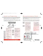
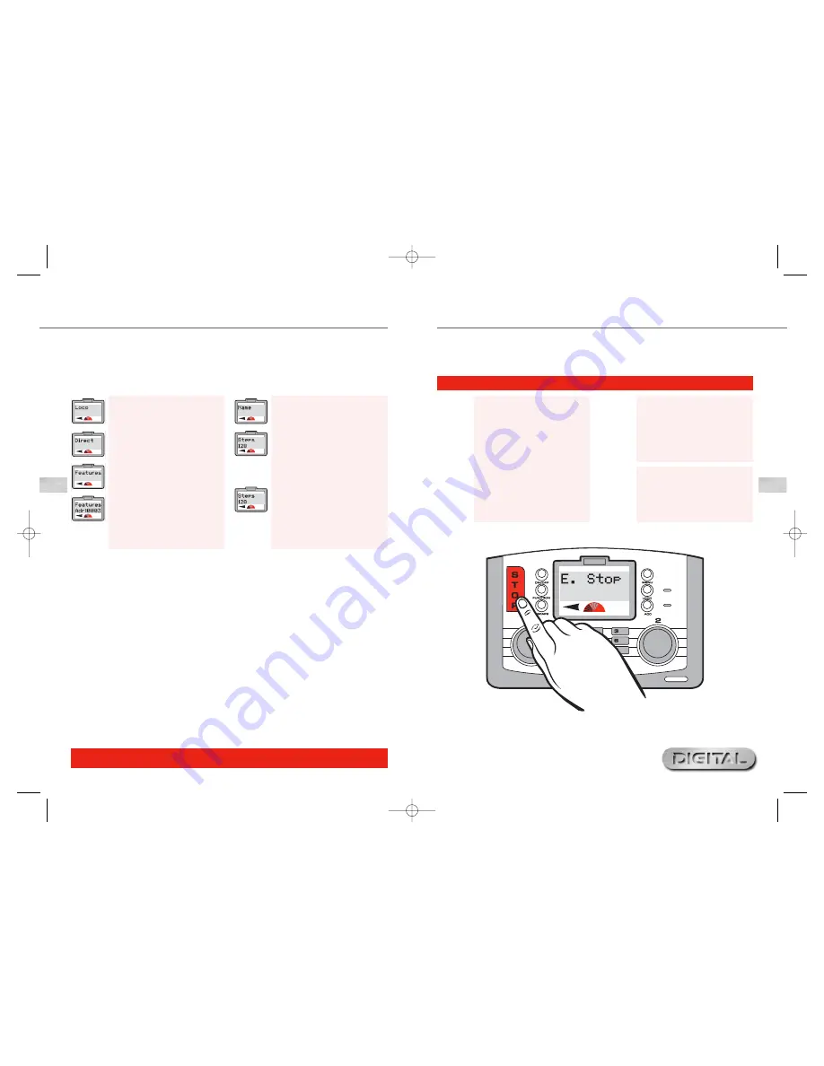
Emergency Stop
Fig 1
Emergency Stop Procedure
1.
Press the
STOP
button located on
the Elite Unit. See Fig 1.
2.
The screen will show “
E. Stop
”
(Emergency Stop).
3.
All activity on the layout will cease.
4.
Allow at least 5 seconds to pass
before restoring the power. Press
STOP
again to restore power to
the layout.
5.
To commence movement each
locomotive will need to be
reselected individually to either
of the controls. This will give the
operator time to reorganise each
locomotive’s movements.
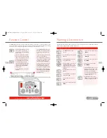
Speed Step Change
1.
Press
Menu
. Screen shows
“
Loco
”.
2.
Press
Control 1
. Screen shows
“
Direct
”.
3.
Rotate
Control 1
until screen shows
“
Features
”. Press
Control 1
.
4.
Screen shows “
Features
Adr:0003
” or the number of the
last locomotive ‘called up’.
5.
Rotate
Control 1
to the locomotive
number required.
6.
Press
Control 1
. Screen shows
“
Name
”.
7.
Rotate
Control 1
until screen
shows “
Steps 128
”. Press
Control 1
.
8.
Rotate
Control 1
until the desired
setting is displayed.
9.
Press
Control 1
to confirm.
Screen shows the steps selected.
10.
Press
Menu
to return to the main
screen.
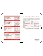
There may be occasions when locomotives fitted with older generation decoders may be required to be controlled
by the
Elite
. Some of these locomotives may require to be “tuned” to the Elite. NB: There are basically three
main levels of speed steps, 14, 28 and 128. The greater the number of speed steps the smoother the acceleration.
All Hornby decoders are factory set at 128 steps. Locomotive 1 will be used in this example.To alter the Speed
Steps place the locomotive on the Programming Track and follow the instructions below.
Elite HBook updated 6.3.07_Q6.qxd 13/3/07 13:09 Page 18


