Installation
Video Recorder - User Manual
24
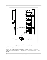
C h a n n e l 4
C h a n n e l 3
C h a n n e l 2
C h a n n e l 1
4 to 2 0 m A o u tp u t
G ro u n d T e rm in a l
+
-
L o a d
+
-
2 4 V
1 2
1 1
1 0
9
8
7
6
5
4
3
2
1
2
S lo t ID
NOTE
- Channels not used as analog outputs can be used
to supply a transmitter with 24 Vdc power
.
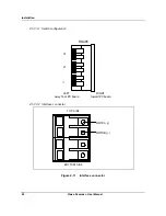
Figure 2-4 AO Board Terminal Block Connections
2.5.6 Digital Outputs
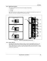
There are three types of Digital Output (DO) boards which provide three types of Off/On control.
1. Relay (alarm) Output
2. DC
Output
3. AC
output
Figure 2-4
shows the terminal block connections for the DC output and AC output DO boards. See
Section 1 for details on all I/O board specifications.
Summary of Contents for VRX180
Page 1: ...Issue 3 03 03 US1I 6228 Video Recorder VRX180 User Manual ...
Page 2: ...Issue 3 03 03 US1I 6228 ...
Page 6: ...iv Video Recorder User Manual ...
Page 48: ...Installation Video Recorder User Manual 34 ...
Page 222: ...Setpoint Profiler Video Recorder User Manual 208 ...
Page 234: ...Online Operations Using Primary Displays Video Recorder User Manual 220 ...
Page 278: ...Appendix A Video Recorder User Manual 264 ...

