U2-S MODEL COMBINATION VIEWING HEAD AND SIGNAL PROCESSOR
9
32-00015—05
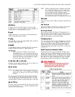
Address
For applications with many flamescanners on single
modbus loop, it is recommended to start with address 11
for burner #1, 21 for burner #2 and so on.
Baud
Speed of Modbus communications (2400, 4800, 9600,
19200). The default baud is 9600.
Parity
Select Modbus checking method (NONE, ODD, or EVEN).
The default parity is NONE.
RS485
Sets Modbus registers to either READ ONLY or read and
writable (WRITE OK). Default is "Read and Write".
IMPORTANT!
Modbus registers should be set to read only
through the menu, or locked using modbus regis-
ter 40182 after system commissioning to prevent
unintended writes to critical parameters. Modbus
register lock requires code from factory, contact
your sales representative for details.
0-20 mA OR 4-20 mA
Sets the current output to either 0-20mA or 4-20mA. The
4-20mA output is the default setting.
Auto Gain
NOTE:
Auto Gain and Auto Filter only adjust solid state
UV, and IR sensors. It will not adjust UV tube gain,
and is non-functional in U2-1016 or U2-1016-PF
models.
This menu selection automatically sets the gain for the
SSUV and IR sensors necessary to generate a total flame
count of approximately 1200. Desired sensors must be
turned on (gain of at least 1) before auto gain is selected.
Auto Filter
This menu selection automatically sets the optimum filter
for the SSUV and IR sensors. It should only be performed
after the AUTO GAIN routine.
NOTE:
While using the Auto Gain and Auto Filter modes,
the system will be adjusting to the firing condi-
tions at the time of implementation. This condi-
tion should be carefully selected to ensure
discrimination through complete load changes
from minimum to maximum and from cold
burner/boiler startup to hot burner/boiler startup.
Default
Tapping will access the file default and factory default sub
menus.
File Default
Selecting file default will reset the currently selected file
parameters to default values (See File Selection).
Factory Default
Selecting factory default will reset all file parameters to
default values, along with additional settings of panel lock
code, baud rate, communications address, file selection
register, and number of active files allowed.
Temperature
This menu displays the U2 internal temperature, software
version, and device hours. Tapping ENTER will bring the
user into the submenu that will allow changes between
displaying Celsius or Fahrenheit, display the software
version, or display the number of hours the unit has been
in operation.
Self Check Lockout Codes
During self check if an error is detected, the flame relay
and self check relay will be de-energized, and the U2 will
display the message "Lockout". The lockout error code may
be viewed at this point by pressing ENTER at touchwheel.
The lockout error code is displayed. Next, pressing enter
resets the device and normal operation is attempted.
WARNING
WARNING
WARNING
Before clearing the lockout, user must ensure
that system is safe for continued operation.
Below are lockout code definition and
recommended actions for each code.
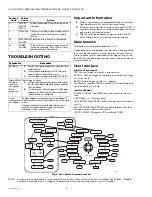
Table 2. Lockout Codes.
401x5
UVSSGAIN x= file 0-7
R/W
401x6
UVSSFILT x = file 0-7
R/W
401x7
IRFILT x = file 0-7
R/W
401x8
IRGAIN x = file 0-7
R/W
401x9
MA GAIN x = file 0-7
R/W
40182
MODBUSLOCK
R/W
40000 -
40300
Other registers unlisted in this range are
special use. DO NOT WRITE.
NA
Register
Address
Register Description
Read
Write
Lockout
Code
Failure
Cause
Action
1
SSUV
SENSOR
SSUV sensor failure. Adjust gain or apply orifice
to lower flamecount. If failure persists, replace
device.
0, 2, 3, 4,
9, 10, 11,
12, 15
INTERNAL
ERROR
Clear Lockout. Verify all parameter settings, all
sensor operation, correct relay operation, and
overall device operation before continuing. If
error persists device must be replaced.
4, 7
MEMORY
ERROR
Clear Lockout. Parameter settings may be
defaulted or corrupted. Verify all parameter
settings and device operation before continuing.
If error persists device must be replaced.
5
UV TUBE
SENSOR
UVtube sensor failure. Device must be replaced.

