U2-S MODEL COMBINATION VIEWING HEAD AND SIGNAL PROCESSOR
32-00015—05
10
TROUBLESHOOTING
Important Information
1.
When connected to an approved Burner control Sys-
tem, additional EMC tests are not required.
2.
All external connection should not exceed 30 VDC. If
higher voltage operation is required, approved inter-
posing relay should be used.
3.
The U2 must be powered using a isolated 24VDC
SELV (Safety Extra Low Voltage) power supply.
Maintenance
There are no user replaceable parts in U2.
Depending upon the application, periodic cleaning of the
lens may be necessary. Usually, the pressurized front of
the lens prevents dirt and debris from depositing on the
lens. Make sure positive pressure is maintained under all
firing conditions.
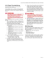
User Interface
Interface Techniques:
TAP: Press a finger on a button and remove.
SCROLL: Press a finger on the glass and move the finger
in circles (twirl).
RAMP: Hold a finger on the + or - button.
Two button interface (BACK and ENTER). Everything else
can be done by scrolling.
Interface Modes:
FLAME DISPLAY: Tap BACK (may require more than on
tap).
HELP: Tap + or - (from display).
LAST MENU: Tap ENTER, move through menu with taps or
scrolls.
ADJUST MODE: Tap ENTER from adjustable menu item,
change value using any technique.
NO YES MODE: Change to YES and tap STORE.
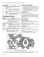
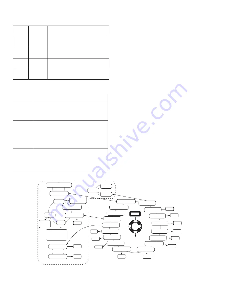
Fig. 6. User interface menu overview.
NOTE:
If a sensor is not available in your model, then no menu item will exist for sensor setting. See Table 1, “Models
and Associated Features.,” on page 2 to determine which sensors are active in your U2 model.
6
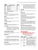
UVTUBE
SENSOR
SUPPLY
UVtube sensor supply failure. Device must be
replaced.
8
IR SENSOR
IR Sensor failure. Adjust gain or apply orifice to
lower flamecount. If failure persists, replace
device.
14
RELAY DRIVE
FAILURE
Relay drive failure, device must be replaced.
16
POWER
FAILURE
Clear Lockout. Verify power source is correctly
set before continuing (24V @120ma). If error
persists device must be replaced.
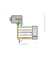
Symptoms
Remedies
No Display
1.
Check 24 VDC power connections and level at red
and black wires.
2.
Turn off power completely for 10-20 seconds to
allow for internal thermal fuse to reset.
3.
Check ambient temperature is below 70C (158F)
Display ON but
flame relay
contact not
closing when
flame
recognized
Check wiring as follows:
1.
Continuity between common (green) wire and yel-
low (this should be closed when power is applied -
Self Check Relay)
2.
If 1 above shows continuity, repeat test with green
and grey wire (Flame relay). Make sure flame LED
shows Flame relay is energized.
Lack of
communicatio
n on Modbus
A unique address must be used for each loop. Address "0"
disables communication. Check communication settings in
menu.
If using a converter, make sure the dip switches are set
correctly. For further troubleshooting, check vendor
information for the converter used.
Lockout
Code
Failure
Cause
Action
M35420
GT32
GU32
FU09
GI32
FI04
GM32
0800
0600
RT01
TD03
*F01
A000
FILE DEFAULT
0000
0000
PANEL LOCK
TIME OUT MIN
FACTORY DEFAULT
RS485
PARITY
HOURS
4 SUB MENUS
LAST MENU
HELP
HELP
°F OR °C
VERSION
ADDRESS-
DEFAULT
127 °F
GAIN TUBE UV-
GAIN SS UV-
FILTER SS UV-
GAIN IR-
FILTER IR-
GAIN MA OUT-
FLAME ON-
FLAME OFF-
FFRT-
TIME DELAY-
FILE
PANEL
COMMS
AUTO GAIN
AUTO FILTER
0->20 OR 4->20
READ ONLY
WRITE ONLY
NONE
ODD
EVEN
2400
9600
38400
115200
4800
19200
57600
BAUD
3425
ENTER
STORE
BACK

