U2-S MODEL COMBINATION VIEWING HEAD AND SIGNAL PROCESSOR
32-00015—05
14
Safety Function of the U2-S Model
The safety function of the U2-S signal processor consists
of a Flame Relay which comprises its safety function and
behaves as follows:
The Flame Relay (Normally Open)
• The Flame Relay will be energized when the product is
powered and a flame on condition is detected for longer
than the time delay value.
• The Flame Relay will be de-energized when the product
is powered, a flame off condition is detected, and the
FFRT (Flame Failure Response Time) has elapsed.
• The Flame Relay will be de-energized when the product
is powered and detects a fault condition.
• The Flame Relay will be de-energized when power to
the product is off.
All U2-S signal processor models contain a Self Check
Relay designed to be energized during normal operation
and de-energized during power off, or detection of a fault.
Proof Test Interval
The Proof test must be conducted every 1 to 5 years. This
range is given to allow for the test to be performed during
the normally scheduled burner shutdown period. It is the
responsibility of the user to perform the proof test in the
specified time frame.
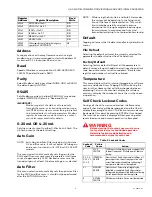
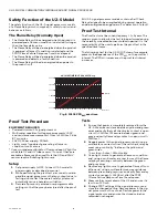
The following chart for the U2-1010S shown for example,
presents the dependence of the PFD
AVG
on the proof test
interval. The PFD
AVG
increases as the proof test interval
increases.
Fig. 8. 1010S PFD
AVG
over time.
Proof Test Procedure
EQUIPMENT REQUIRED
• Powered Uniscan 2S signal processor
• Multimeter capable of voltage measurements < 50V,
and resistance measurements 1 Ohm to 1MOhm. Fluke
87 or similar.
• 24V DC Power supply < 500mA
• Light source* capable of generating a flame on
condition for all sensors.
* Use an incandescent bulb for IR sensor, deep UV light for
solid state UV and UV tube sensors. If none of these are
available a flame may be used. Note that IR, and SSUV
sensors require flickering light source.
Setup
1.
Set power supply to OFF. Connect U2-S model to
power supply as described in manual.
2.
While performing the proof test, disconnect or disre-
gard the signal processor so that any outputs due to
testing do not affect the overall safety system and
potentially cause a hazardous situation.
3.
Record all previously entered user programmable
settings so that they may be restored after the proof
test.
Tests
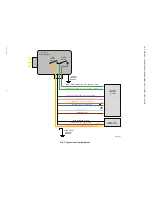
1.
Ensure that power is completely removed form the
U2-S. Measure resistance between yellow and green
wires and verify that self check relay contact is open
circuit ( >1MOhm ). Measure between green and
gray, and verify flame relay contact is open circuit (>
1MOhm).
2.
Reapply power to the signal processor and, using a
multimeter, ensure closure of the self check relay by
measuring continuity * between the yellow and
green wires.
* Less than ~5ohm / 50foot cable
3.
Use a light source to generate a flame on condition
and, using a multimeter, ensure closure of the flame
relay by measuring continuity between the green
and gray wires.
4.
Remove any light source to generate a flame off con-
dition and, using a multimeter measure resistance
between green and gray wires, and verify flame relay
contacts are open ( > 1MOhm), after the FFRT
(Flame Failure Response Time) has elapsed.
5.
Measure the current draw of the U2 and ensure it is
less than 120 mA.
6.
Change FFRT settings of the signal processor and
store the changed setting. Remove power to the sig-
nal processor for 10 seconds. Restore power to the
signal processor and ensure the stored value has
remained unchanged.
MCR35675
0
1
2
3
4
5
6
7
8
9
10
PFDavg
U2-1010S TIME IN YEARS VS PFDavg
2.53E-04
2.03E-04
1.53E-04
1.03E-04
5.27E-05
2.71E-06

