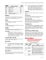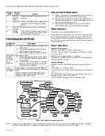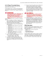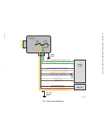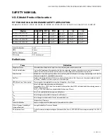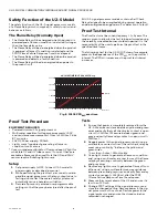
U2-S MODEL COMBINATION VIEWING HEAD AND SIGNAL PROCESSOR
7
32-00015—05
NOTE:
Only the pertinent menu will be displayed. For
example, for UVtron only sensor (U2-1016S and
U2-1016S-PF), only UVTron gain will be dis-
played. UVSS and IR gain will not be visible.
Display, as seen by the user, is shown in
BOLD RED
in the list
below as it appears in sequence.
U2 MENU PARAMETER
SETTINGS
CAUTION
CAUTION
!
If the display shows "9999" while in operation, it
indicates flamecount has exceeded maximum
range of device. Reduce appropriate sensor
gain(s) so that Flame count is about 1.5 to 3
times Flame OFF threshold settings. If
unsuccessful, orificing or increased sight pipe
length may be required.
Gain UVTron
GTXX -
Displays the current UVTRON tube sensor gain
(adjustable 0-99). The default value is 32.
Gain SSUV
GÛXX -
Displays the current solid state UV sensor gain
(adjustable 0-99). The default value is 75. Adjusting the
gain too high may result in lockout due to saturation of the
sensor.
Flicker Filter Setting for SSUV
FÛ0X -
Displays the current solid state UV flicker filter
setting (adjustable 0-9). The default value is 3.
Gain IR
GIXX -
Displays the current IR sensor gain (adjustable 0-
99). The default value is 75. Adjusting the gain too high
may result in lockout due to saturation of the sensor.
Flicker Filter Setting for IR
FI0X -
Displays the current IR sensor flicker filter setting
(adjustable 0-9). The default value is 3.
Flicker settings indicated below apply to SSUV and IR.
These are high pass filter setting:
Gain MA OUT
GMXX -
Displays the current multiplier for analog output
(adjustable 0-99). The default value is 30, and will result in
approximately 12mA analog out at 1700 flamecount, and
20mA at 3425 counts. The ma gain setting allows for
scaling of the analog output value proportional to the
flamecount at full load. For example, increasing the gain,
increases the analog output for a given flamecount.
Adjusting the MA gain does not alter gain settings of
UVTron, SSUV, or IR. After completing flame setpoint
configuration, adjustment to the MA gain may be used to
set MA output at full system load.
Flame On Threshold Setting
Displays the current Flame On threshold settings. It is
important to note that flame count must reach this
threshold in order for the flame relay to energize. After the
flame relay is energized, the flame count may drop below
Flame ON threshold but must remain above Flame Off
threshold (refer to FFRT below). Range is 51- 3425 flame
count.
NOTE:
The Flame ON threshold setting must be 1 digit
above Flame OFF setting.
Flame OFF Threshold Setting
Displays the current Flame OFF threshold settings. Flame
count must remain above Flame Off threshold setting
otherwise flame relay will be de-energized after Flame
Failure response time has expired. Range is 50- 3424
flame count.
NOTE:
The Flame Off threshold setting must be 1 digit
below Flame On setting.
Flame Failure Response Time
(FFRT)
RT0X -
Displays the current Flame Failure response time in
seconds. Flamecount must remain above Flame Off
threshold setting otherwise the flame relay will be de-
energized after Flame failure response time has expired.
FFRT selection is 1, 2 or 3 seconds. Default setting is 1
second.
IMPORTANT
The FFRT must be set to 1 second, to meet require-
ments defined in European Standard EN298,
unless the application standard allows for longer
response time. Care must be used to ensure that
the overall response time of the system is accept-
able for safe operation.
Flame On Time Delay
TD0X -
Displays the current Flame On time delay in
seconds. The flame relay will be energized after the
flamecount has remained above the flame ON threshold,
and the time delay has elapsed. This feature is useful in
applications where flames from other sources are
temporarily present in target area, such as grate fired
boilers. Selection is 0,1, 2 or 3.
NOTE:
The time delay also reduces Trial for Ignition by
the set time. Default setting is 3 seconds.
Setting
HZ
Setting
HZ
Setting
HZ
0
9
4
52
8
215
1
16
5
75
9
300
2
24
6
100
3
33
7
155

