U2-S MODEL COMBINATION VIEWING HEAD AND SIGNAL PROCESSOR
11
32-00015—05
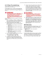
U2-S Flame Threshold Setup
Desired target burner flamecount during normal
operation is 1200 to 2000 counts.
Using multiple sensors is useful for monitoring different
fuels, pilot/main flame monitoring, or for a high level of
discrimination. See feature chart on page 2 for application
sensors.
WARNING
WARNING
WARNING
Positioning of flame scanner, along with gain and
filter settings must result in a background
radiation flamecount that is less than the flame
off setpoint! (Example: If target flame is
extinguished, but background flame(s) are still
present, flamecount must fall below flame off
setpoint).
Recommended Ideal Flame On and Flame Off threshold
settings:
1.
Adjust available sensor filters to 0, and gain of each
sensor so that flamecount under normal operation is
approximately 1500 to 2000 counts total when view-
ing target flame under normal firing rate.
2.
Take a reading of the Flame On and Flame OFF
flamecount values at minimum firing rate and Maxi-
mum firing rate:
f.
Target burner Flame ON flame count at lowest
firing rate = AL
g. Target burner Flame Off, flame count at lowest
firing rate = BL
h. Target burner Flame ON flame count at highest
firing rate = AH
i.
Target burner Flame Off, flame count at highest
firing rate = BH
j.
Select AL if AL < AH, otherwise use AH value.
Let us call this value = X
k. Select BH if BH < BL otherwise use BL value.
Let us all call this value =Y
3.
Use X, Y, along with formulas below to arrive at new
Flame ON, and Flame OFF thresholds.
Flame ON set point = 0.75X + 0.25Y
Flame OFF set point = 0.25X + 0.75Y
4.
Using new values for Flame On and Flame Off
threshold, calculate FLAME ON/Flame OFF ratio.
The ratio of 1.5 or higher is desirable. Adjust flame
ON and flame OFF thresholds to calculated values in
step 3.
5.
Extinguish target flame while maximum background
radiation is present. Observe flamecount, and
increase filter setting(s) of sensor(s) to decrease
total flamecount present from background radia-
tion. The resulting background radiation flamecount
should be adjusted to minimum. Verify that resulting
flamecount falls below the flame off setpoint. If not,
continue adjusting gain and filter settings, or adjust
target flame sighting.
WARNING
WARNING
WARNING
After setup is complete, installer must test for
background flame radiation below flame off
setpoint when target flame is extinguished over
all conditions. Failure to verify this may result in
unsafe operation.
6.
When filtering settings are complete, operate system
once again with all flames present over minimum
and maximum load, and verify proper flame thresh-
old operation. If no further adjustment is necessary,
threshold setup is complete. If gain or filter adjust-
ments are necessary, repeat step 5 to confirm back-
ground radiation below flame OFF setpoint as any
adjustments will affect both the target and back-
ground radiations.
XRAY Radiation
Xray radiation does not affect signal processor, or viewing
head IR sensor performance, and does not adversely
affect viewing head tube sensor performance under the
following conditions:
• Radiation Source of 65 Curie Iridium 192
• Distance > 5'
• Exposure type Direct
• UV tube gain set to default
• Flame off threshold >600
If viewing heads are subjected to more severe conditions,
system must be tested to ensure that radiation does not
cause flame-counts above flame off threshold. If this
occurs, flame off threshold must be increased, UV tube
gain must be reduced, or lead shielding must be used.

