Honeywell THOR VM1 Reference Manual Download Page 319

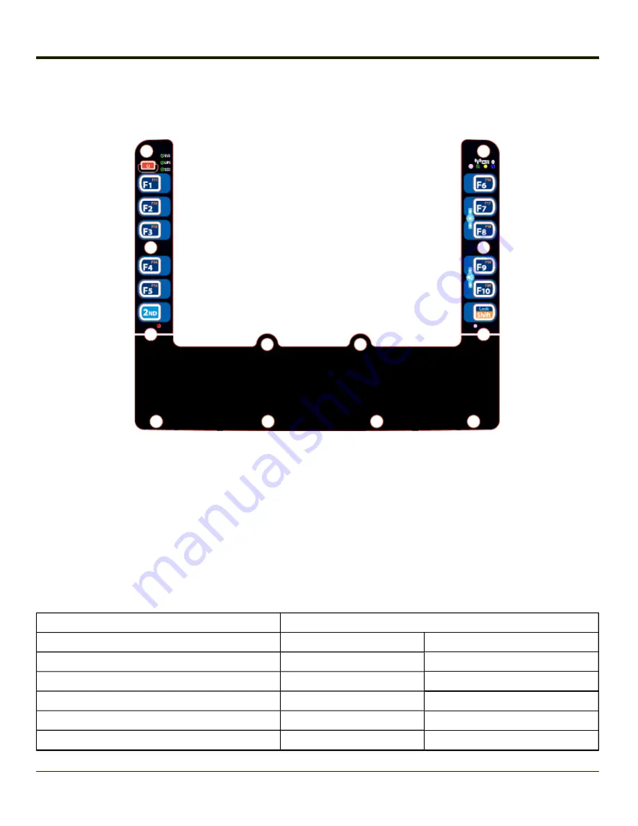
12-Key Keypad Key Map

The 12-key keyboard is available on the Thor VM1 running Windows CE 6.0.

l

Because the keyboard only has 12 keys, all functions are not visible (or printed on the keyboard). Therefore the Thor
VM1 keyboard supports what is called

hidden keys

-- keys that are accessible but not visible on the keyboard.

l

A key or combination of keys can be remapped to provide a single keypress, a string of keypresses or to execute an
application or command. All key

remapping

is done using the KeyPad option in the Control Panel (Start > Settings >

Control Panel > Keypad).

l

The keyboard keys are backlit. The

keyboard backlight

and the display share the same timer, which is configured in

Start > Settings > Control Panel > Power

By default, when the display is On, the keyboard backlight is also On. The

keyboard backlight can be disabled, see

Start > Settings > Control Panel > Options > Misc

tab.

l

The warmboot behavior of CapsLock can be set via the Misc tab in

Start > Settings > Control Panel > Options

.

Note:

When automatic brightness control is enabled for a Thor VM1 with an Outdoor display, the manual

display brightness controls in the table below have no effect.

To get this Key / Function

Press These Keys in this Order

Power On/Suspend

Power

F1

F1

F2

F2

F3

F3

F4

F4

F5

F5

8-7

Summary of Contents for THOR VM1

Page 1: ...Thor VM1 Vehicle Mounted Computer Microsoft Windows Embedded CE 6 Operating System Reference Guide ...

Page 2: ...Intel Corporation or its subsidiaries in the United States and other countries Summit Data Communications Inc Summit Data Communications the Summit logo and The Pinnacle of Performance are trademarks of Summit Data Communications Inc The Bluetooth word mark and logos are owned by the Bluetooth SIG Inc Symbol is a registered trademark of Symbol Technologies MOTOROLA MOTO MOTOROLA SOLUTIONS and the ...

Page 3: ...Subsystem 2 2 Audio Interface 2 2 Card Slots 2 2 CompactFlash CF Slot 2 2 Secure Digital SD Slot 2 2 Bluetooth LXEZ Pairing 2 3 WWAN 2 3 GPS 2 3 Power 2 4 Vehicle DC Power Supply 2 4 External AC Power Supply 2 4 Uninterruptible Power Supply 2 4 Backup Battery 2 5 Fuse 2 5 Power Modes 2 6 On Mode D0 2 6 User Idle Backlight Off Mode D1 2 6 System Idle Display Off Mode D2 2 6 Suspend mode D3 2 6 Crit...

Page 4: ...le Cable 2 15 D9 Male Connector 2 15 USB Host Connector 2 16 USB Client Connector 2 16 Power Supply Connector 2 17 CANbus Audio Connector 2 18 Headset Adapter Cable 2 19 D15 Female Connector 2 19 Quick Connect Headset Connector 2 20 CANbus Cable 2 21 D15 Female Connector 2 21 9 Pin J1939 Deutsch Connectors 2 22 Antenna Connections 2 23 Antenna Connector Pin 2 23 Vehicle Remote Antenna Mount 2 23 I...

Page 5: ... 34 Display 2 35 Touchscreen 2 35 Touchscreen Defroster 2 35 Screen Blanking 2 35 Display Backlight Control 2 35 Disconnect UPS Battery 2 36 Install SD Card 2 37 Install SIM Card 2 38 Field Replaceable Front Panel 2 39 How To Replace Front Panel 2 39 Field Replaceable UPS Battery 2 42 How To Replace Front Panel 2 42 Chapter 3 Software 3 1 Introduction 3 1 Operating System 3 1 Windows CE Operating ...

Page 6: ...EXE 3 9 WAVPLAY EXE 3 9 Thor VM1 Command line Utilities 3 9 PrtScrn EXE 3 10 Desktop 3 11 Desktop Icons 3 11 Taskbar 3 12 My Device Folders 3 13 Wavelink Avalanche Enabler Optional 3 13 Internet Explorer 3 13 Start Menu Program Options 3 14 Communication 3 14 ActiveSync 3 14 Connect and LXEConnect 3 15 Start FTP Server Stop FTP Server 3 15 Summit 3 15 Certs 3 15 Command Prompt 3 15 eXpress Scan 3 ...

Page 7: ...t 3 24 Version Tab and the Registry 3 24 Languages 3 24 Identifying Software Versions 3 25 MAC Address 3 25 Accessibility 3 26 Administration for AppLock 3 27 Factory Default Settings AppLock 3 28 Setup a New Device 3 29 Administration Mode 3 29 End User Mode 3 30 Passwords 3 30 End User Switching Technique 3 31 Using a Stylus Tap 3 31 Using the Switch Key Sequence 3 31 Hotkey Activation hotkey 3 ...

Page 8: ...tooth Device Properties 3 59 Settings 3 60 Turn Off Bluetooth 3 60 Options 3 61 Reconnect 3 62 Options 3 63 About 3 65 Using Bluetooth 3 66 Initial Configuration 3 66 Subsequent Use 3 67 Bluetooth Indicators 3 68 Bluetooth Bar Code Reader Setup 3 69 Thor VM1 with Label 3 69 Thor VM1 without Label 3 70 Bluetooth Beep and LED Indications 3 71 Bluetooth Printer Setup 3 71 Easy Pairing and Auto Reconn...

Page 9: ...Edit Buttons 3 87 Match List Rules 3 88 Add Prefix Suffix Control 3 89 Symbologies 3 89 Ctrl Char Mapping 3 90 Translate All 3 90 Parameters 3 90 Translate All 3 90 Character 3 91 Replacement 3 91 List Box 3 91 Assign Button 3 91 Delete Button 3 91 Custom Identifiers 3 92 Parameters 3 92 Buttons 3 93 Control Code Replacement Examples 3 94 Bar Code Processing Examples 3 95 Processing Tab 3 96 About...

Page 10: ... Panel 3 114 Transcriber 3 114 Internet Options 3 115 Keyboard 3 118 KeyPad 3 119 KeyMap Tab 3 120 How to Remap a Single Key 3 120 How to Remap a Key Sequence 3 120 How to Remap an Application 3 121 How to Remap a Command 3 121 LaunchApp Tab 3 122 RunCmd Tab 3 123 License Viewer 3 124 Mixer 3 125 Output Panel 3 125 Input Panel 3 126 Mouse 3 127 Network and Dialup Options 3 128 Create a New Connect...

Page 11: ...Registry 3 145 Remove Programs 3 146 Screen Control 3 147 Screen Blanking 3 148 Current Level 3 148 Automatic Brightness Control 3 149 Stylus 3 150 Double Tap 3 150 Calibration 3 150 System 3 151 General Tab 3 151 Memory Tab 3 152 Device Name Tab 3 152 Copyrights Tab 3 153 Terminal Server Client Licenses 3 154 Volume and Sounds 3 155 Good Scan and Bad Scan Sounds 3 156 WiFi Control Panel 3 157 Cha...

Page 12: ...r Uninstall Process 5 2 Stop the Enabler Service 5 2 Update Monitoring Overview 5 3 Mobile Device Wireless and Network Settings 5 4 Preparing a Device for Remote Management 5 5 Using Wavelink Avalanche to Upgrade System Baseline 5 6 Part 1 Bootstrapping the RMU 5 6 Part 2 Installing Packages 5 6 Version Information on Mobile Devices 5 6 User Interface 5 7 Enabler Configuration 5 7 File Menu Option...

Page 13: ...reless Zero Config Utility 6 3 How to Switch Control to SCU 6 3 Main Tab 6 4 Auto Profile 6 5 Admin Login 6 5 Profile Tab 6 7 Buttons 6 8 Profile Parameters 6 9 Status Tab 6 11 Diags Tab 6 12 Global Tab 6 13 Custom Parameter Option 6 14 Global Parameters 6 15 Sign On vs Stored Credentials 6 19 How to Use Stored Credentials 6 19 How to Use Sign On Screen 6 19 Windows Certificate Store vs Certs Path...

Page 14: ...ser Certificate 6 50 Verify Installation 6 52 Chapter 7 Technical Specifications 7 1 Thor VM1 7 1 Dimensions 7 1 Quick Mount Smart Dock 7 2 Environmental Specifications 7 2 Thor VM1 7 2 Network Card Specifications 7 3 Summit 802 11a b g 7 3 Bluetooth 7 3 Chapter 8 Key Maps 8 1 64 Key QWERTY Keypad Key Map 8 1 12 Key Keypad Key Map 8 7 IBM Terminal Emulation 8 9 IBM 3270 8 9 IBM 5250 8 10 Chapter 9...

Page 15: ...nnects to vehicle power The dock provides conditioned input power for the Thor VM1 Peripheral connections are on the dock The Thor VM1 is designed to easily be removed from the dock with a latch on the lower rear of the Thor VM1 housing Since the dock remains attached to the vehicle the Thor VM1 computer can easily be moved from one vehicle equipped with a Quick Mount Smart Dock to another vehicle...

Page 16: ...ton to accept the EULA terms and the Thor VM1 continues the startup process The EULA is not presented to the user again Tap the Decline button to decline the EULA and the Thor VM1 will reboot It will continue to reboot until the Accept button is tapped with the stylus Note The EULA will be presented after any operating system upgrade or re installation including language specific operating systems...

Page 17: ...Components Front View 1 Power Button 2 Speakers 3 Ambient Light Sensor 4 Microphone 1 3 ...

Page 18: ... for Padlock on Thor VM1 and Dock 9 Provision for Laptop Security Cable on Thor VM1 10 Power Switch on Dock 11 Power Connector on Dock 12 Fuse on Dock 13 SD Card Access Panel On Thor VM1 14 Strain Relief Clamps on Dock 15 RAM Ball on Dock Access Panels Access Panel Door is labeled with SSD and SD 1 CompactFlash Hard Drive 2 SD Secure Digital Memory Card Slot Access Panel Door is labeled with SIM 1...

Page 19: ...versity with two internal or external antennas Power management for the network card is configured with the Summit Client Utility Central Processing Unit The CPU is a 1 6MHz Intel Atom processor The operating system is Microsoft CE 6 0 The OS image is stored on an internal flash card and is loaded into DRAM for execution 2 1 ...

Page 20: ...display supports screen blanking to eliminate driver distraction when the vehicle is in motion Audio Interface Speakers are located on the bottom front of the Thor VM1 An headset adapter cable provides a connection for headset operation When a headset is plugged into the adapter cable the main speakers are disabled A microphone is located at the upper right of the Thor VM1 display near the Thor VM...

Page 21: ...ption is based on the length of the user s passcode Bluetooth simultaneously supports one printer as a slave Bluetooth device and one scanner either as a slave or as a master Bluetooth device l The LED on the Bluetooth scanner illuminates during a scanning operation l Bar code data captured by the Bluetooth scanner is manipulated by the settings in the Thor VM1 Scanner Properties control panel app...

Page 22: ...o either a 120V 60Hz supply or outside North America to a 230V 50Hz supply using the appropriate detachable cordset In all cases connect the external AC supply to a properly grounded source of supply provided with maximum 15 Amp overcurrent protection 10 Amp for 230V circuits Please refer to the wiring instructions including appropriate cautions and warnings in the Thor VM1 User Guide Uninterrupti...

Page 23: ...nd should last five years with normal use before it requires replacement Note The backup battery should only be changed by authorized service personnel Fuse The Thor VM1 uses a 10A time delay slow blow fuse that is externally accessible and user replaceable The fuse is located on the back of the Quick Mount Smart Dock Should it need replacement replace with same size rating and type of fuse Littel...

Page 24: ...en if external power is connect and off if external power is not connected The device transitions to this mode from System Idle after the Suspend timeout period has passed without a primary event occurring Additionally the power button can be used to enter or exit Suspend mode l If the Thor VM1 is On pressing the power button immediately transitions the unit to Suspend l If the Thor VM1 is in Susp...

Page 25: ... as long the system event occurs System primary events include l Serial data transfer l USB data transfer Wake Source Events These events wake the Thor VM1 from suspend l Power button l Touch on the touchscreen l Any keypress on the keyboard l USB connect disconnect l Truck power on or off i e ignition key l RTC l Bluetooth connection l External power connection l Serial port CTS control line l He...

Page 26: ...dock is connected to external power the dock delivers power to the Thor VM1 Thor VM1 Power Button The power button is located at the top left of the Thor VM1 If the Thor VM1 is Off pressing the power button starts the power up sequence Note This assumes that the Thor VM1 is docked in a powered Quick Mount Smart Dock or that the internal UPS battery has a sufficient charge to power the Thor VM1 If ...

Page 27: ...f the Thor VM1 is already on and one of the above events occurs the Thor VM1 continues to run however the power management scheme may change based on the connection to external power Auto On Disabled Note When Auto On is disabled the Ignition Input signal if connected via the Thor VM1 vehicle power supply cable is monitored If the Thor VM1 is Off and Ignition Input is Inactive the Thor VM1 remains...

Page 28: ...ode scanner screen blanking cable serial printer or PC l COM2 connects to a serial bar code scanner screen blanking cable serial printer or PC l USB accepts a dongle cable with a USB Host port and a USB Client port l CANbus Audio accepts a cable with connections for a mono headset microphone or a cable with CANbus adapters The power connector is on the dock Antenna connectors are located on the re...

Page 29: ...r an external bar code scanner Pin 9 of COM1 or COM2 may also be configured to provide RI If a COM port is not being used for a scanner it can be used for screen blanking when the vehicle is in motion Pinout Pin Signal Description 1 DCD Data Carrier Detect Input 2 RXD Receive Data Input 3 TXD Transmit Data Output 4 DTR Data Terminal Ready Output 5 GND Signal Power Ground 6 DSR Data Set Ready Input...

Page 30: ...utput and pin 8 Clear to Send Input of a DB9 female connector to a switch that provides an electrical conductive connection on vehicle motion Do not enable Screen Blanking until the cable is properly connected to the specified COM port Serial Cable Customer built cable with the following specifications DB9 Female Function with Screen Blanking Box Function with Switch 1 Not Used Not Used 2 Not Used...

Page 31: ... the display on the Thor VM1 is blanked When motion is no longer detected the Screen Blanking Box provides a connection between the output feeds After the configured Screen On delay if any the Thor VM1 screen is displayed Please refer to the wiring instructions including appropriate cautions and warnings in the Thor VM1 User Guide Screen Blanking with Switch In applications where it is impractical...

Page 32: ...able to any port serial USB Audio CAN etc Pin Signal Description 1 GND Common ground 2 USBC_D USB client data signal 3 USBC_D USB client data signal 4 USB_H1_PWR USB host 1 5V output power 5 GND Common ground 6 GND Common ground 7 USB_H1_D USB host 1 data signal 8 USB_H1_D USB host 1 data signal 9 USBC_VBUS USB client 5V detect from attached host 2 14 ...

Page 33: ...nal Description 1 GND Common ground 2 USBC_D USB client data signal 3 USBC_D USB client data signal 4 USB_H1_PWR USB host 5V output power 5 GND Common ground 6 GND Common ground 7 USB_H1_D USB host 1 data signal 8 USB_H1_D USB host 1 data signal 9 USBC_VBUS USB client 5V detect from attached host 2 15 ...

Page 34: ...urrent Limited 2 USB_H1_D USB D 3 USB_H1_D USB D 4 GND USB Power Return Shell CGND Chassis Ground USB Client Connector Pin Signal Description 1 5V_USB USB Power Current Limited 2 USB_H1_D USB D 3 USB_H1_D USB D 4 GND USB Power Return Shell CGND Chassis Ground 2 16 ...

Page 35: ...ehicle s chassis ground to be connected internally to the conductive chassis of the computer The Thor VM1 internal power supply can accept DC input voltages in the range of 10 to 60 Volts DC Pin Signal Description 1 V In 10 60V DC input 2 V In 10 60V DC input 3 V In input 4 V In input 5 GND Chassis ground 6 Ignition 0V to 60V to start terminal 2 17 ...

Page 36: ...o and CANbus simultaneously Pin Signal Name Description 1 CAN reserved 2 CAN_L CAN_L bus line dominant low 3 CAN_GND CAN Ground 4 CAN reserved 5 GND Optional ground 6 Audio return Headset return 7 Audio output Headset output 8 Mic input Microphone input 9 Mic return Microphone return 10 Audio Return 11 GND Optional ground 12 CAN_SHLD 13 CAN_H CAN_H bus line dominant high 14 CAN reserved 15 CAN_V O...

Page 37: ...ction for a headset D15 Female Connector Pin Signal Description 1 Not used 2 Not used 3 Not used 4 Not used 5 Not used 6 Audio return Headset return 7 Audio output Headset output 8 Mic input Microphone input 9 Mic return Microphone return 10 Not used 11 Not used 12 Not used 13 Not used 14 Not used 15 Not used 2 19 ...

Page 38: ...Quick Connect Headset Connector Pin Signal Description 1 Mic input Microphone input 2 Mic return Microphone return 3 Audio output Headset output 4 Audio return Headset return 2 20 ...

Page 39: ... Female Connector Pin Signal Description 1 Not used 2 CAN_L CAN_L bus line dominant low 3 CAN_GND CAN ground 4 CAN reserved 5 GND Ground 6 Not used 7 Not used 8 Not used 9 Not used 10 Not used 11 GND Optional ground 12 CAN_SHLD 13 CAN_H CAN_H bus line dominant high 14 CAN reserved 15 CAN_V CAN external power supply 2 21 ...

Page 40: ...939 Female Socket J1939 Male Pin Signal Description A CAN_GND CAN Ground B CAN_V Option CAN external Power Supply C CAN_H CAN_H bus line dominant high D CAN_L CAN_L bus line dominant low E CAN_SHLD F Not used G Not used H Not used J Not used 2 22 ...

Page 41: ...el GPS Antenna Connector 4 MOBILE NET Blue label WWAN Antenna Connector Antenna Connector Pin When the Thor VM1 is ordered with the internal antenna option the 802 11 antenna connectors on the back are not connected to the 802 11 radio Instead the internal antenna is connected to the 802 11 radio Vehicle Remote Antenna Mount The external antennas can be remotely mounted on the vehicle See the Thor...

Page 42: ...ing of keypresses or to execute an application or command All key remapping is done using the KeyPad option in the Control Panel Start Settings Control Panel Keypad l The keyboard does not have a NumLock indicator or key NumLock is always On l The keyboard keys are backlit The keyboard backlight and the display share the same timer which is configured in Start Settings Control Panel Power By defau...

Page 43: ...IBM 3270 Overlay 2 25 ...

Page 44: ...IBM 5250 Overlay 12 Key Keyboard The 12 key keyboard is available on the Thor VM1 running Windows CE 6 0 2 26 ...

Page 45: ...lication or command All key remapping is done using the KeyPad option in the Control Panel Start Settings Control Panel Keypad l The keyboard keys are backlit The keyboard backlight and the display share the same timer which is configured in Start Settings Control Panel Power By default when the display is On the keyboard backlight is also On The keyboard backlight can be disabled see Start Settin...

Page 46: ...he 2nd key followed by the superscript key Once the 2nd state is enabled by pressing the 2nd key the Secondary Mode LED is illuminated and the 2nd state is enabled until another key is pressed The 2nd key is toggled on with a 2nd key press and then immediately off with another 2nd key press For example Press 2nd and F1 to generate F11 Ctrl and Alt Key LEDs Note Ctrl and Alt keys and the associated...

Page 47: ...LEDs 2 Connection LEDs 3 2nd LED 4 Shift CapsLock LED 5 Ctrl LED 6 Alt LED 7 Shift CapsLock LED 64 key keyboards only System LEDs 1 SYS System Status LED 2 UPS Uninterruptible Power Supply LED 3 SSD Solid State Drive LED 2 29 ...

Page 48: ...conds off l Suspend Off External power not present l Off l Suspend Green blinking slowly External power present Approximately one half second on 1 5 seconds off CPU temperature less than 20ºC Heater warming CPU for 30 seconds Green blinking slowly External power not present Approximately one half second on 1 5 seconds off CPU temperature less than 20ºC Need to move unit to warmer environment 2 30 ...

Page 49: ...r l Any charging fault l Out of charging temperature range l No UPS present l Charge timeout External Power Not Present LED Behavior Status Off l Unit off l UPS not present Solid Amber UPS supplying power and discharging Solid Red Approximately 2 minutes runtime until shutdown SSD Solid State Drive LED LED Behavior Status Flashing Green SSD read or write activity Off No SSD read or write activity ...

Page 50: ...ED Behavior Status Blue Blinking Slowly Bluetooth is paired but not connected to a device Blue Blinking Medium Bluetooth is paired and connected to a device Blue Blinking Fast Bluetooth is discovering Bluetooth devices Off Bluetooth hardware has been turned off The Bluetooth LED blinks once every 6 seconds when the Bluetooth client is paired but not connected It blinks once for a very short time e...

Page 51: ...the keypad is in Shift mode Shift mode is invoked for one keypress l Pressing the Shift key places the system in Shift mode l To exit Shift mode press the Shift key again Solid Green l When solid Green indicates the keypad is in Caps Lock mode Caps Lock mode is invoked until canceled l Pressing the 2nd key followed by the Shift key places the system in Caps Lock mode l To exit Caps Lock mode press...

Page 52: ...ey keypad LED Behavior Status Solid Green l Indicates the Alt modifier key is active Alt mode is invoked for the next keypress only l Pressing the Alt key a second time exits this modifier mode and turns off the LED Off Alt mode is not invoked 2 34 ...

Page 53: ...yboard attached to the Thor VM1 to access the control panel ro re enable or recalibrate the touch screen Touchscreen Defroster Extended temperature versions of the Thor VM1 contain a touchscreen defroster The touchscreen defroster can be disabled when not needed Start Settings Control Panel Peripherals The defroster trip point is configurable The defroster is always disabled when the device is ope...

Page 54: ... stable surface 4 Using a 2 Philips bit loosen the M3 screws and then remove the tethered access panel with the SIM label This panel is on the right hand side when the Thor VM1 is face down with the top away from the user 5 Locate the small push button located just below the SIM card installation slot 6 Press the push button to disconnect the UPS The UPS battery maintains its charge but is disconn...

Page 55: ...Place the Thor VM1 face down on a stable surface 4 Using a Phillips screwdriver not supplied loosen the screws and then remove the tethered access panel with the SSD and SD label This panel is on the left hand side when the Thor VM1 is face down with the top away from the user 5 Locate the SD card installation slot 6 Slide the SD card into the slot The label side front of the SD card faces toward ...

Page 56: ...lace the Thor VM1 face down on a stable surface 4 Using a Phillips screwdriver not supplied loosen the screws and then remove the tethered access panel with the SIM label This panel is on the right hand side when the Thor VM1 is face down with the top away from the user 5 Locate the SIM card installation slot 6 Slide the SIM card into the slot 7 Reattach the access panel torquing the screws to 4 5...

Page 57: ...64 key ANSI keyboard with standard touchscreen l 64 key 3270 keyboard with standard touchscreen l 64 key 5250 keyboard with standard touchscreen l 12 key keyboard with standard touchscreen l 64 key ANSI keyboard with cold storage touchscreen l 64 key 3270 keyboard with cold storage touchscreen l 64 key 5250 keyboard with cold storage touchscreen l 12 key keyboard with cold storage touchscreen How ...

Page 58: ...5 Carefully lift the front panel away from the device A Slot on Thor VM1 body B Wiring connector on Thor VM1 body 2 40 ...

Page 59: ... the fourteen 14 captive M3 screws In the order shown in the top figure above use a 2 Philips bit and torque the screws to 6 7 inch pounds 9 Reinstall the Thor VM1 in the Quick Mount Smart Dock 10 When the Thor VM1 is placed in the powered dock the UPS battery automatically reconnects 11 Restart the Thor VM1 12 When restarted the Thor VM1 automatically recognizes the keyboard type 12 or 64 keys 13...

Page 60: ...Thor VM1 is field replaceable Should the UPS battery fail it can easily be replaced to minimize downtime How To Replace Front Panel 1 Place the Thor VM1 on a clean well lit surface before performing the UPS battery replacement 2 Place the Thor VM1 in Suspend by pressing the Power button 3 Remove the Thor VM1 from the Quick Mount Smart Dock 4 Disconnect the UPS 5 Loosen the fourteen 14 captive M3 s...

Page 61: ...d gently disconnect the UPS battery wiring from the Thor VM1 8 Remove the old battery and set it aside 9 Inspect the battery well to verify the two foam pads are still in place 10 Align the wiring connector on the new UPS battery with the connector on the Thor VM1 Gently press the connector into place until the retaining tab snaps into place 11 Place the UPS battery into the well Note the orientat...

Page 62: ...nnectors B and C in figures above are also aligned 13 Gently press the front panel into place 14 Tighten the fourteen 14 captive M3 screws In the order shown in the top figure above use a 2 Philips bit and torque the screws to 6 7 inch pounds 15 Reinstall the Thor VM1 in the Quick Mount Smart Dock 16 When the Thor VM1 is placed in the powered dock the UPS battery automatically reconnects The UPS b...

Page 63: ...ures Operating System Your Thor VM1 operating system is Microsoft Windows Embedded CE 6 The Thor VM1 operating system revision is displayed on the Desktop This is the factory default setting for the Desktop Display Background Windows CE Operating System Note For general use instruction please refer to commercially available Windows CE user s guides or the Windows CE on line Help application instal...

Page 64: ... menu name Display the corresponding menu Underlined letter in a command name on an open menu Carry out the corresponding command ESC Cancel the current task The touchscreen provides equivalent functionality to a mouse l A touch on the touchscreen is equivalent to a left mouse click l Many items can be moved by the drag and drop method touching the desired item moving the stylus across the screen ...

Page 65: ...ot need to be held down simultaneously l For the 12 key keypad use the 2nd F5 Shift keypress sequence to reboot the Thor VM1 The keys may be pressed in sequence they do not need to be held down simultaneously This reboot sequence also works on the 64 key keypad If 2nd F5 is remapped to another key pressing 2nd F5 generates the remapped key However if the next keypress is Shift the Thor VM1 reboots...

Page 66: ... only from System Startup Windows Startup is parsed too early in the boot process so it has no effect Executables in System Startup must be the actual executable not a shortcut because shortcuts are not parsed by Launch Saving Changes to the Registry The Thor VM1 saves the registry when you l Warmboot either from the Registry control panel the warmboot command or the reboot keypress sequence l Res...

Page 67: ...ode result manipulation l ActiveSync l Transcriber l Internet Explorer l Word Viewer l Excel Viewer l PDF Viewer l PowerPoint Viewer Note that the viewer applications allow viewing documents but not editing them ActiveSync ActiveSync is pre loaded on mobile devices Using Microsoft ActiveSync you can copy files from your Thor VM1 to your desktop laptop and vice versa After an ActiveSync relationshi...

Page 68: ...ation the Wavelink Avalanche Enabler will be an auto launch application This behavior can be modified by accessing the Avalanche Update Settings panel through the Enabler Interface Software Development See Also CE API Programming Guide The CE API Programming Guide documents device specific API calls for the Thor VM1 It is intended as an addition to Microsoft Windows CE API documentation A Software...

Page 69: ... and the CAB file must be reinstalled Order is used to force a sequence of events Order 0 is first and Order 99 is last Order must be greater than 4 for the Thor VM1 Two items which have the same order will be installed in the same pass but not in a predictable sequence There are two optional fields that may be added 1 Delay is used to add a delay after the item is loaded before the next is loaded...

Page 70: ...keys specifying EXE or BAT files the executing process is started and then Launch will continue leaving the loading process to run independently For other persist keys including CAB files Launch will wait for the loading process to complete before continuing This is important for example to ensure that a CAB file is installed before the EXE files from the CAB file are run l Note that the auto laun...

Page 71: ...ed settings in the registry REGDUMP EXE Registry dump Saves a copy of the registry as a text file The file REG TXT is located in the root folder The Thor VM1 includes a Load User Defaults option in the Registry control panel This is the preferred method for saving a backup of the registry Save the registry file to the System folder on the Thor VM1 persistent storage or copy the file to a PC WARMBO...

Page 72: ...tart Run and type prtscrn and tap OK or press Enter There is a 10 second delay before the screen print is made The device beeps and the screen captured file scrnnnnn bmp is placed in the System folder The numeric filename is incremented by 1 each time the PrtScrn function is activated The command is not case sensitive 3 10 ...

Page 73: ...ycle Bin Following are a few of the other icons that may be on the Thor VM1 Desktop Please Contact your representative about the latest updates and upgrades for your operating system Icon Function Access files and programs Storage for files that are to be deleted Discover and then pair with nearby discoverable Bluetooth devices Storage for downloaded files applications Connect to the Internet intr...

Page 74: ...1 but not installed When the enabler is installed the Avalanche icon is displayed on the desktop The demo version of Wavelink Telnet CE is installed on all devices Please Contact your representative for licensing information When installed license details are maintained in the Wavelink tab in the License Viewer control panel Start button Access programs select from the Favorites listing documents ...

Page 75: ... for l IP address DHCP or static IP l RF network SSID l DNS hosts primary secondary tertiary l Subnet mask l Enabler update Related Manual Using Wavelink Avalanche The Thor VM1 has the Avalanche Enabler installation files loaded but not installed on the mobile device when it is shipped The installation files are located in the System folder on CE devices The installation application must be run ma...

Page 76: ...ordPad Opens an ASCII notepad Remote Desktop Connection Log on to a Windows Terminal Server RFTerm Option Terminal emulation application Settings Access to all Control Panels a shortcut to the Network and Dialup Control Panel and access to Taskbar options Summit Set Summit radio network parameters Transcriber Enter data using the stylus on the touchscreen Wavelink Avalanche Option Remote managemen...

Page 77: ...op FTP Server These shortcuts call the Services Manager to start and stop the FTP server The server defaults to Off for security unless it is explicitly turned on from the menu Summit Start Settings Control Panel Summit Use this option to set up radio client profiles The Summit Control Panel can also be accessed by doubletapping the Summit icon in the taskbar or on the desktop Certs The Certs opti...

Page 78: ...ayer Start Programs Media Player There are few changes in the Windows CE version of Media Player as it relates to the general desktop Windows PC Microsoft Media Player options After the Media Player application is running click the button to access Media Player Help File Viewers The following applications are included l JETCET PDF Viewer l Office 2003 Excel Viewer l Office 2003 PowerPoint Viewer l...

Page 79: ...p the Options button Transcriber Options Start Settings Control Panel Input Panel are available only when Transcriber is selected as the active input method Tap the button or the Help button to access Transcriber Help Windows Explorer Start Programs Windows Explorer There are a few changes in the Windows CE version of Windows Explorer as it relates to the general desktop PC Windows Explorer option...

Page 80: ... cases tapping the icon in the Taskbar opens the related application Refer to Start Help for an explanation of standard Windows CE taskbar icons Following are a few of the unique Thor VM1 taskbar icons that may appear in the Taskbar These icons are in addition to the Windows CE taskbar icons Wireless Zero Config Inactive Connected Not Connected Clicking on the icon opens the Wireless Zero Config u...

Page 81: ...l Clicking on the icon opens the Gobi Connection Manager UPS battery charge indicator Percent of battery charge is indicated External power connected connected and UPS battery charging Current time Clicking the time display opens the Date Time control panel Click this icon to return to the Desktop AppLock switchpad Input method keyboard input panel transcriber CapsLock active 3 19 ...

Page 82: ...cards should be performed on a clean well lit surface l Always perform OS updates when the Thor VM1 has a dependable external power source connected to the Thor VM1 Procedure 1 Verify a dependable power source is applied to the Thor VM1 and will stay connected during the upgrade procedure 2 Warmboot the Thor VM1 before beginning the update process 3 Establish an ActiveSync connection between the T...

Page 83: ...up When the Embedded BIOS screen Phoenix Technologies is displayed press the Del key to enter BIOS setup From the screen displayed select System Setup Utility Use the arrow keys to move around the screen Boot Order To view or edit the boot order select the Boot tab By default the first device in the boot order is USB Hard Drive The second device is the Windows CE Image If a USB drive such as a thu...

Page 84: ...and keypad backlight properties and timers Gobi Connection Manager Set parameters for the Wireless Wide Area Network client if installed Input Panel Select the current key data input method Select custom key maps Internet Options Set General Connection Security Privacy Advanced and Popups options for Internet connectivity Keyboard Select a Key Map or font Set key repeat delay and key repeat rate K...

Page 85: ...rograms in their entirety Screen Control Configure screen blanking and automatic screen brightness control Stylus Set double tap sensitivity properties and or calibrate the touch panel System Review System and Computer data and revision levels Adjust Storage and Program memory settings Enter device name and description Review copyright notices Terminal Server Client Licenses Select a server client...

Page 86: ...INE Software LXE Version in the registry To add a user application to the Version panel create a new string value under the HKLM Software LXE Version key The string name should be the Application name to appear in the Version window The data for the value should be the version number to appear in the Version window Version strings can be equal to or less than 254 characters Because the strings are...

Page 87: ...alled software is included in this list and the list varies depending on the applications loaded on the Thor VM1 The Image line displays the revision of the system software installed Refer to the last three digits to determine the revision level MAC Address The Network IP tab displays the MAC address of the network card 3 25 ...

Page 88: ...eckbox to enable this option Tap the Settings button to view or change parameters Mouse MouseKeys is disabled by default Tap the Use MouseKeys checkbox to enable this option Tap the Settings button to view or change parameters General Automatic reset is disabled by default Tap the Turn off accessibility features checkbox to enable this option and use the dropdown option to assign a timer Notificat...

Page 89: ...ld reset the Administrator may need to reconfigure the AppLock parameters The assumption in this section is that the first user to power up a new mobile device is the system administrator Note AppLock Administrator Control panel file Launch option does not inter relate with similarly named options contained in other Thor VM1 Control Panels Note A few applications do not follow normal procedures wh...

Page 90: ...o at Boot Enabled Auto at Boot Retries 0 Auto at Boot Delay 10 sec Auto Re launch Enabled Auto Re launch Retries 0 Auto Re launch Delay 0 sec Manual Launch Disabled Allow Close Disabled Security Panel Hotkey Activation key Shift Ctl A Password Blank Options Panel Launch timeout 60000 Replace timeout 20000 Restart timeout 20000 Status Panel Filename System applock txt View Level None Log Level None...

Page 91: ...ect a view level on the Status tab screen if desired 7 Tap OK 8 Press the hotkey sequence to launch AppLock and lock the configured application s 9 The device is now in end user mode Administration Mode Administration mode gives full access to the mobile device hardware and software configuration options The administrator must enter a valid password when a password has already been assigned before...

Page 92: ...se all other applications before switching to end user mode to minimize the screen flicker Windows accelerator keys such as Alt F4 are disabled Passwords A password must be configured If the password is not configured a new device switches into Administration mode without prompting for a password In addition to the hotkey press a mode switch occurs if inaccurate information has been configured or ...

Page 93: ...the user taps the Switchpad icon a menu is displayed showing the applications available to the user The user can tap an application name in the popup menu and the selected application is brought to the foreground The previous application continues to run in the background Stylus taps affect the application in focus only When the user needs to use the Input Panel they tap the Keyboard option Input ...

Page 94: ...Ctrl Spc The key sequence switches the focus between one application and another Data entry affects the application running in the foreground only Note that the system administrator may have assigned a different key sequence to use when switching applications 3 32 ...

Page 95: ...within three tries or the password prompt is removed and the device remains in end user mode with the focus returned to the locked application Without entry of a valid password the switch into Administrator mode will not occur The password prompt is displayed if a password has been configured When the valid password is entered the Administration Control panel is displayed When a valid password is ...

Page 96: ...1 Enter the Order in which the application is to be loaded or presented to the end user Applications are launched in lowest to highest number order and do not need to be sequential Internet Default is Disabled Enable the Internet checkbox to use the End user Internet Explorer EUIE EXE When the checkbox is enabled the Internet Menu and Internet Status are available See the section titled End user I...

Page 97: ...he user for all configured applications Clear Button Tap the Clear button to clear all currently displayed Filename or Application information The Global settings are not cleared Scroll Buttons Use the left and right scroll buttons to move from application setup screen to application setup screen The left and right buttons update the information on the screen with the previous or next con figured ...

Page 98: ...r representative for assistance downloads and AppLock update availability When clicked displays the Launch options panel for the Filename selected on the Administration panel Note Launch order is determined by the Order specified in the Application tab The Order value does not have to be sequential 3 36 ...

Page 99: ... selected application when it is automatically launched at bootup Delay default is 10 seconds Valid values are between 0 seconds no delay and 999 seconds The Auto At Boot delay is associated for each application it will be either a value specified by the Administrator or it will be the delay default value At startup when a delay has been assigned for each application AppLock waits for the delay as...

Page 100: ...or the end user or by the end user after the application terminates Retries Default is 0 tries Retries is the number of times AppLock will try to re launch the application The retry count is reset after an application is successfully launched and controlled by AppLock Valid values are between 0 no tries and 99 tries or 1 for infinite Infinite tries ends when the application successfully launches D...

Page 101: ...ions active status When Manual Launch is disabled for an application and Allow Close is enabled for the application when the end user closes the specific application it is no longer available shown on the Switchpad When Auto At Boot and Manual Launch are both disabled for a specific application the application is 1 not placed on the list of approved applications for end user manual launch and 2 ne...

Page 102: ...ernet checkbox in the Application tab of the Administrator applet The internet application should then be entered in the Application text box When the Internet checkbox is enabled the Menu and Status check boxes are available Enabling the Menu checkbox displays the EUIE menu which contains navigation functions like Back Forward Home Refresh etc functions that are familiar to most Internet Explorer...

Page 103: ...the Input Panel Also hotkeys entered via the SIP are not guaranteed to work properly when switching operational modes For example if the Ctrl key is pressed followed by A Ctrl A is entered in the text box If another key is pressed after a normal key press the hotkey sequence is cleared and a new hotkey sequence is started A normal key is required for the hotkey sequence and is unlike pressing the ...

Page 104: ...aunch after the application has been called For example if the application takes time to launch and then initialize before a display window is created use this delay to specify the delay period Replace timeout This timeout specifies the period of time for AppLock to wait after an initial screen like a password prompt screen is replaced by another application window Restart timeout This specifies t...

Page 105: ...ogfile from the Browse dialog tap OK Note If your Status Panel does not look like the figure shown above you may have the Single Application version which does not have as many options View Error Error status messages are logged when an error occurs and is intended to be used by the administrator to deter mine why the specified application cannot be locked Process Processing status shows the flow ...

Page 106: ... however to reduce registry use the administrator may want to select None after verifying the configuration Tap the Clear button to clear the status information from the registry l None l Error l Processing l Extended l All Save As When the Save As button is selected a standard Save As dialog screen is displayed Specify the path and filename If the filename exists the user is prompted whether the ...

Page 107: ... switching user modes they are not allowed to enter key combinations that are reserved by installed software applications Only RFTerm key combinations are validated When RFTerm is installed on the mobile device and an RFTerm restricted key sequence is specified as a hotkey sequence by the Administrator the following error message is displayed in a message box Selected hotkey is not allowed Please ...

Page 108: ... length of the encrypted password LOG_EX Encrypted data len Length of the encrypted password LOG_EX hProcess Handle of the application being locked LOG_EX Key pressed A key has been pressed and trapped by the hotkey processing LOG_EX The status information is being saved to a file and the file has been opened successfully LOG_EX Address of keyboard hook procedure failure AppLock found the kbdhook ...

Page 109: ...been pressed and trapped by the HotKey processing LOG_EX Ctrl Processing the hotkey and backdoor entry LOG_EX Decrypt acquire context failure Unable to decrypt password LOG_ERROR Decrypt acquired context OK Decryption process ok LOG_EX Decrypt create hash fail ure Unable to decrypt password LOG_ERROR Decrypt created hash OK Decryption process ok LOG_EX Decrypt failure Unable to decrypt password LO...

Page 110: ...g LOG_PROC ESSING Enter FullScreenMode Entering the function that switches the screen mode In full screen mode the taskbar is hidden and disabled LOG_PROC ESSING Enter GetAppInfo Processing is at the beginning of the function that retrieves the application information from the registry LOG_PROC ESSING Enter password dialog Entering the password dialog processing LOG_PROC ESSING Enter password time...

Page 111: ...Exit ToAdmin Exiting the function that handles the mode switch into admin mode LOG_PROC ESSING Exit ToUser Exiting the user mode switch function LOG_PROC ESSING Exit ToUser Registry read failure The AppName value does not exist in the registry so user mode cannot be entered LOG_PROC ESSING Exit verify password no pwd set Exiting password verification LOG_PROC ESSING Exit verify password response f...

Page 112: ... first loads it loads a dll that contains the keyboard hook processing This message is logged prior to the load attempt LOG_PROC ESSING Open failure The status information is being saved to a file and the file open has failed This could occur if the file is write protected If the file does not exist it is created LOG_ERROR Open registry failure If the Administration registry key does not exist the...

Page 113: ...nd trapped by the HotKey processing LOG_EX Shift Processing the hotkey and backdoor entry LOG_EX Show taskbar The taskbar is now being made visible and enabled LOG_PROC ESSING Switching to admin back door The system is currently in user mode and is now switching to admin mode The switch occurred because of the backdoor key presses were entered by the administrator LOG_PROC ESSING Switching to admi...

Page 114: ...ocessing continues LOG_ERROR Unable to move taskbar The taskbar is moved when switching into user mode This prevents them from being vis ible if the application is exited and restarted by the timer This error does not affect the screen mode switch processing continues LOG_ERROR Unhook taskbar wndproc failure AppLock could not remove its control of the taskbar This error does not affect AppLock pro...

Page 115: ...s in the system tray and shows four levels of charge 100 75 50 25 At a point below 25 the system status LED will turn red and the gas gauge icon will turn red indicating the battery is low The battery gauge icon is enabled by default but can be disabled on the Thor VM1 Battery control panel Jacked is shown in the Status box when the UPS battery is receiving external power 3 53 ...

Page 116: ...uter is connectable Enabled Computer is discoverable Disabled Prompt if devices request to pair Enabled Continuous search Disabled Filtered Mode Enabled Printer Port on COM 7 Disabled unchecked by default in both Filtered and Non Fil tered Modes The option is dimmed in Non Filtered Mode Logging Disabled Computer Friendly Name System Device Name Reconnect Report lost connection Enabled Report when ...

Page 117: ...r Bluetooth devices l It is not necessary to disconnect a paired scanner and printer before a different scanner or printer is paired with the Thor VM1 l The target Bluetooth device should be as close as possible up to 32 8 ft 10 meters Line of Sight to the Thor VM1 during the pairing process Assumption The System Administrator has Discovered and Paired targeted Bluetooth devices for the Thor VM1 T...

Page 118: ...e Bluetooth connection between the paired device and the Thor VM1 is lost There may be audible or visual signals as paired devices disconnect from the Thor VM1 Bluetooth Device List The discovered paired devices may or may not be identified with an icon Discovered devices without an icon can be paired as a Scanner or a Printer The Bluetooth panel assigns an icon to the device name An icon with a r...

Page 119: ...active Clear Button Deletes all devices from the Device table that are not currently paired A dialog box is presented Delete all disconnected devices Yes No Tap the Yes button to remove disconnected or deleted devices from the device table The devices are removed from the Device table after any reboot sequence or after closing and reopening the Bluetooth panels Tap the No button to make no changes...

Page 120: ...e highlighted Bluetooth scanner or Bluetooth imager Pair as Printer Send data to the highlighted Bluetooth printer Pair as Serial Device Communicate with the highlighted serial Bluetooth device This option is available when Filtered Mode is disabled Disconnect Stop the connection between the Thor VM1 and the highlighted paired Bluetooth device Delete Remove an unpaired device from the Bluetooth de...

Page 121: ...on the Bluetooth Properties panel cannot be changed by the user The data displayed is the result of the device Query performed during the Discovery process The Status dialog box reflects the current state of the highlighted device 3 59 ...

Page 122: ...unchecked whether Bluetooth connection is enabled or disabled Turn Off Bluetooth Tap the button to toggle the Bluetooth client On or Off The button title changes from Turn Off Bluetooth to Turn On Bluetooth Default The default value is Bluetooth On 3 60 ...

Page 123: ...tops searching after 30 minutes This option draws power from the Main Battery Filtered Mode This option is Enabled by default Determines whether the Bluetooth client discovers and displays all serial Bluetooth devices in the vicinity Filtered Mode is disabled unchecked or the discovery result displays Bluetooth scanners and printers only Filtered Mode is enabled checked When Filtered Mode is disab...

Page 124: ...Reconnect Note These options can still be checked or unchecked whether Bluetooth connection is enabled or disabled 3 62 ...

Page 125: ...here may be an audio or visual signal when a connection between a paired active device fails to re connect A visual signal may be a dialog box placed on the display notifying the user the connection between one or all of the previously paired Bluetooth devices has failed Tap the X button or ok button to close the dialog box Possible reasons for failure to reconnect Timeout expired without reconnec...

Page 126: ... of Clear Pairing Table on Boot controls whether the pairing table is populated on boot l When Auto Reconnect is enabled checked and Auto Reconnect on Boot is disabled unchecked devices are not reconnected on boot but are reconnected in other situations example return from out of range l When Auto Reconnect is enabled checked and Clear Pairing Table on Boot is enabled checked devices are not recon...

Page 127: ...nel lists the assigned Computer Friendly Name that other devices may discover during their Discovery and Query process the Bluetooth MAC address and software version levels The data cannot be edited by the user 3 65 ...

Page 128: ... enabled only Bluetooth printers or Bluetooth scanners imagers are recognized and displayed in the Bluetooth panel All other Bluetooth devices are ignored Initial Configuration 1 Select Start Settings Control Panel Bluetooth or tap the Bluetooth icon in the taskbar or on the desktop 2 Tap the Settings Tab 3 Change the Computer Friendly Name at the bottom of the Settings display The Bluetooth Thor ...

Page 129: ...r VM1 to receive scanner data 7 Tap Pair as Printer to set up the Thor VM1 to send data to the printer 8 Tap Serial Device when Filtered mode is disabled to set up the Thor VM1 to communicate with a Bluetooth serial device 9 Tap Disconnect to stop pairing with the device Once disconnected tap Delete to remove the device name and data from the Thor VM1 Bluetooth Devices list The device is deleted f...

Page 130: ...ters Suspend Mode is turned Off or leaves the Thor VM1 Bluetooth scan range the Bluetooth connection between the paired device and the Thor VM1 is lost There may be audible or visual signals as paired devices disconnect from the Thor VM1 Bluetooth LED Legend Blue blinking slowly Bluetooth is active but not connected to a device Blue blinking medium Bluetooth is paired and connected to a device Blu...

Page 131: ...identifier for the Thor VM1 The mobile Bluetooth scanner imager requires this information before discovering pairing connecting or disconnecting can occur Important The Thor VM1 Bluetooth address identifier label should remain protected from damage rips tears spills soiling erasure etc at all times It may be required when pairing connecting and disconnecting new Bluetooth bar code readers Thor VM1...

Page 132: ...se L lowercase n lowercase k uppercase B and then the Bluetooth address 12 hex digits no colons For example LnkB0400fd002031 Create and print the label Scan the Thor VM1 Bluetooth address bar code label with the Bluetooth bar code reader The devices are paired The Bluetooth bar code reader responds with a series of beeps and LED flashes Note After scanning the Thor VM1 Bluetooth label if there is ...

Page 133: ...r is reset the sequence is repeated Contact your representative for assistance Bluetooth Printer Setup The Bluetooth managed device should be as close as possible in direct line of sight with the Thor VM1 during the pairing process 1 Open the LXEZ Pairing Panel 2 Tap Discover Locate the Bluetooth printer in the Discovery panel 3 Tap and hold the stylus or doubletap on the Bluetooth printer ID unti...

Page 134: ...nd then returned within range See Also Reconnect Note Configuration elements are persistent and stored in the registry Setup the Bluetooth module to establish how the user is notified by easy pairing and auto reconnect events AppLock if installed does not stop the end user from using the Bluetooth application nor does it stop other Bluetooth enabled devices from pairing with the Thor VM1 while App...

Page 135: ...trusted by the Thor VM1 mobile device user These values may change based on the type of network security resident in the client access point or the host system Tap the Import button to import a digital certificate file Tap the View button to view a highlighted digital certificate Tap the Remove button to remove highlighted certificate files Tap the button and follow the instructions in the Windows...

Page 136: ...wedge Any data handling to be applied to the scanned data for example strip leading or trailing characters must be programmed into the scan engine via configuration bar codes or handled by the application accepting the data Use the options on the control panels to set Thor VM1 data collection keyboard wedge parameters enable or disable allowed symbologies and assign scan key settings Assign baud r...

Page 137: ...ufacturer s programming guide The manufacturer s guides are usually shipped with the bar code reader l The body worn Bluetooth Ring Scanner module may be using a Symbol 4400 Ring Imager or a Symbol 955 Ring Scanner The BTRS module is configured by scanning the bar codes in the Bluetooth Ring Scanner Guide Return to Factory Default Settings After scanning the engine specific bar code to return the ...

Page 138: ...railing data bytes unconditionally 5 Parse for and strip if found Data Options strings 6 Replace any control characters with string as configured 7 Add prefix string to output buffer 8 If Code ID is not stripped add saved code ID from above to output buffer 9 Add processed data string from above to output buffer 10 Add suffix string to output buffer 11 Add a terminating NUL to the output buffer in...

Page 139: ...Parity None Data Bits 8 Power on Pin 9 Enabled COM2 Tab External serial port Baud Rate 9600 Stop Bits 1 Parity None Data Bits 8 Power on Pin 9 Enabled Data Options Tab Enable Code ID None Symbology Settings All Control Character Translate All Disabled Custom IDs Name blank Processing Tab Enable buffered key output Enabled Same buffer limit 32 Delay between buffers 75 ms 3 77 ...

Page 140: ...led The data collection device laser scanner laser imager external or wireless Send Key Messages WEDGE Default Enabled When Send Key Messages WEDGE is checked any data collection scan is converted to keystrokes and sent to the active window When this checkbox is not checked the application will need to use the set of Scanner APIs to retrieve the data from the scanner driver Note that this latter m...

Page 141: ...e external connected or wireless device for information on configuring the device Note COM default values are restored after a cold boot or operating system upgrade COM1 supports 5V switchable power on Pin 9 for tethered scanners Power on Pin 9 To configure the COM port to supply power to an external scanner tethered to the COM1 port check the checkbox for Power on Pin 9 5V The default is On enabl...

Page 142: ...e external connected or wireless device for information on configuring the device Note COM default values are restored after a cold boot or operating system upgrade COM2 supports 5V switchable power on Pin 9 for tethered scanners Power on Pin 9 To configure the COM port to supply power to an external scanner tethered to the COM2 port check the checkbox for Power on Pin 9 5V The default is On enabl...

Page 143: ...l Defining custom Code IDs l Disable processing of specified bar code symbologies l Rejecting bar code data that is too short or too long l Stripping characters including Code ID leading or trailing characters and specified bar code data strings l Replacing control characters l Adding a prefix and a suffix Enable Code ID Choose an option in the Enable Code ID drop down box None Disables transmissi...

Page 144: ... add a prefix or suffix to a bar code before transmission Ctrl Char Mapping Define the operations the Wedge performs on control characters values less than 0x20 embedded in bar codes Custom Identifiers Defines an identifier that is at the beginning of bar code data which acts as a Code ID After a Custom Identifier is defined Symbology Settings can be defined for the identifier just like standard C...

Page 145: ...t enable or disable the Code ID as that function is controlled by the Enable Code ID box on the Data Options tab The Symbology drop down box contains all symbologies supported based on the Code ID selected above An asterisk appears in front of symbologies that have already been configured or have been modified from the default value Each time a Symbology is changed the settings are saved as soon a...

Page 146: ...om their defaults If a particular symbology has been configured the entire set of parameters from that symbologies screen are in effect for that symbology In other words either the settings for the configured symbology will be used or the default settings are used not a combination of the two If a symbology has not been configured does not have an next to it the settings for All are used which is ...

Page 147: ...here are customized settings uncheck the Enable checkbox for the All symbology This results in disabling all symbologies except the customized ones Min This field specifies the minimum length that the bar code data not including Code ID must meet to be processed Any bar code scanned that is less than the number of characters specified in the Min field is rejected The default for this field is 1 Ma...

Page 148: ... is enabled and no prefix or suffix is configured the processing will return a zero byte data packet which will be rejected The operation of each type of stripping is defined below Leading This strips the number of characters specified from the beginning of the collected data not including Code ID The data is stripped unconditionally This action is disabled by default Trailing This strips the numb...

Page 149: ...he Add button changes to Insert Enter data into both the Name and ID Code fields and click the Insert button The data is added to the selected line in the Custom IDs list Edit Double click on the item to edit Its values are copied to the text boxes for editing The Add button changes to Replace When Replace is clicked the values for the current item in the list are updated Clear All When no item in...

Page 150: ...Z will strip off the suffix XYZ The string ABC XYZ will strip both prefix and suffix together More than one in a configuration string is not allowed The User Interface will not prevent it but results would not be as expected as only the first is used in parsing to match the string l The question mark wildcard may be used to match any single character in the incoming data For example the data AB D ...

Page 151: ...tions have already occurred stripping settings do not affect the prefix The prefix is added to the output buffer for the Symbology selected from the pull down list If All is selected the prefix is added for any symbology that has not been specifically configured Add Suffix To enable a suffix check the Suffix checkbox and enter the desired string in the textbox The default is disabled unchecked wit...

Page 152: ...ge provides a one to one mapping of control characters to their equivalent control character sequence of keystrokes If control characters are translated the translation is performed on the bar code data prefix and suffix before the keystrokes are simulated Parameters Translate All This option is grayed unless the user has Send Key Messages WEDGE on the Main tab selected In Key Message mode when th...

Page 153: ...n box typing the replacement in the Replacement edit control according to the formats defined above and then clicking the button The assigned replacement is then added to the list box above the Assign button For example if Carriage Return is replaced by Line Feed by specifying J or 0x0A in the configuration the value 0x0d received in any scanned bar code or defined in the prefix or suffix will be ...

Page 154: ...ked for a custom ID code the list is compared in the order displayed in this dialog box After adding changing and removing items from the Custom IDs list click the OK button to save changes and return to the Bar Code panel Parameters Name text box Name is the descriptor that is used to identify the custom Code ID Names must be unique from each other however the Name and ID Code may have the same v...

Page 155: ...values are copied to the text boxes for editing The Add button changes to Replace When Replace is clicked the values for the current item in the list are updated Clear All When no item in the Custom IDs list is selected clicking the Clear All button clears the Custom ID list and any text written and not yet added or inserted in the Name and ID Code text boxes Remove The Clear All button text chang...

Page 156: ...e hat encoded text is translated to the equivalent hex value Carriage Return M Value 0x0d in a bar code is converted to the value 0x0d Escaped hat encoded text The hat encoding to pass through to the application Horizontal Tab I Value 0x09 in a bar code is converted to the text I Hex encoded text The hex encoded text is translated to the equivalent hex value Carriage Return 0x0A Value 0x0D in a ba...

Page 157: ...sulting Data EAN 128 C11234567890123 bbb1234567890xxx EAN 128 C111234567890123 bbb11234567890xxx EAN 128 C1123 rejected too short EAN 13 E01234567890987 ccc E04567890yyy EAN 13 E01231234567890987 ccc E0234567890yyy EAN 13 E01234 ccc E0yyy I2 5 I04444567890987654321 rejected too long I2 5 I04444567890123 ddd7890zzz I2 5 I0444 dddzzz I2 5 I022245622 ddd45zzz Code 93 G0123456 rejected disabled Code 9...

Page 158: ...is panel have no effect when RFTerm is the application with the input focus Enable buffered key output Default is enabled checked Click the checkbox to turn off buffered key output Same buffer limit Default is 32 ms Raise or lower this value as desired Delay between key buffers Specifies the number of milliseconds to delay after each character in the scanned bar code is processed as a keystroke Th...

Page 159: ...l Panel Data Collection About tab This tab displays the Data Collection Wedge driver version installed in the Thor VM1 The version number shown in the image below is used only as an example your version number will be different 3 97 ...

Page 160: ... 2 and last 8 This 24 character bar code is Code 128 l 20 character length with first two characters 00 strip first 0 no characters and last 4 On the Data Options tab set Enable Code ID to Custom Create four custom IDs using 1 for EAN 128 bar code and 0 for Code 128 bar code l c1 Code C1 l c2 Code C1 l c3 Code C0 24 character bar code is Code 128 l c4 Code C1 Custom symbology setup is assigned in ...

Page 161: ...Click the Bar Code Data button Click the Add button Add the data for the match codes Refer to the previous section Bar Code Data Match List for instruction Scan a bar code and examine the result 3 99 ...

Page 162: ...Hat Encoding 3 100 ...

Page 163: ...3 101 ...

Page 164: ...ttings Current Time Midnight Time Zone GMT 05 00 Daylight Savings Enabled There is very little functional change from general desktop or laptop Date Time Properties options Double tapping the time displayed in the Desktop Taskbar causes the Date Time Properties screen to appear The Sync button if available activates a utility that will set the clock using a network time server 3 102 ...

Page 165: ... Panel Dialing Set dialup properties for internal modems not supplied or supported on the Thor VM1 Factory Default Settings Location Work Area Code 425 Tone Dialing Enabled Country Region 1 Disable Call Waiting Disabled blank 3 103 ...

Page 166: ...es Saved changes take effect immediately Factory Default Settings Background tab Image Windows CE Image on background Disabled Appearance tab Schemes Windows Standard Backlight tab Battery power 3 seconds External power and user idle 2 minutes Background There is very little change from general desktop PC Display Properties Background options Select an image from the dropdown list or tap the Brows...

Page 167: ...igh Contrast White for monochrome displays and Windows Standard for color displays Tap the Save button to save any changes renaming the scheme if desired Tap the Delete button to delete schemes Tap the Apply button to apply the selected scheme to the display Backlight Default value is 2 minutes for external power 30 seconds when operating on the internal UPS battery 3 105 ...

Page 168: ...llow and green bars There is no WWAN connection present 105 dbm to 86 dbm signal strength 85 dbm to 66 dbm signal strength 65 dbm to 46 dbm signal strength 45 dbm or higher signal strength Initial Use Some carriers such as AT T and T Mobile require a SIM card for use on their networks Other carriers such as Verizon use a CDMA network and must be activated Please refer to the sections below for mor...

Page 169: ...7 Reinstall the Thor VM1 in the Dock 8 Resume the Thor VM1 from suspend Activate To activate service for a CDMA carrier such as Verizon complete the necessary entries on the Activate tab 3 107 ...

Page 170: ...or message is displayed Contact your representative for assistance 3 Tap the Update Firmware button 4 The update process may take a minute or so to complete The status of the Gobi 2000 radio is displayed in the lower left corner of this tab An error message is displayed in this location if the firmware selected requires a SIM card and no SIM card is installed in the Thor VM1 Connection status is a...

Page 171: ...he Automatic radio button for Activation Type 2 Automatic activation requires an Activation Code Enter the Activation Code in the Activation Code text box and tap Activate 3 All other text boxes are grayed out as no additional entries are required for automatic activation 4 Verify the activation process is successful by reviewing the message below the Activation Type group Manual Activation 1 Sele...

Page 172: ...The Connection Manager automatically connect when necessary such as when Internet Explorer is launched Data Connection Test Tap the Connect button to make a temporary test connection to validate the carrier account Entries identified with an asterisk are used to configure the test connection Tap the Save Connection Data button to save the connection parameters 3 110 ...

Page 173: ...ically connect when necessary such as when Internet Explorer is launched Data Connection Test Tap the Connect button to make a temporary test connection to validate the carrier account Entries identified with an asterisk are used to configure the test connection Tap the Save Connection Data button to save the connection parameters 3 111 ...

Page 174: ...adio You must confirm that you want to rest the data Use this button with caution as it takes a longer time for the GPS to establish a valid fix after the data is cleared After the GPS establishes a coordinate fix the Where am I button is active Tapping this button activates Internet Explore to display a Google map of the current location The GPS time and NMEA National Maritime Electronics Associa...

Page 175: ...About This tab displays information on the Gobi 2000 radio installed in the Thor VM1 3 113 ...

Page 176: ...nables both Tap the Options button to set the size of the keys displayed on screen and whether Transcriber gestures are enabled or disabled Transcriber When choosing Transcriber as the Current Input Method first tap the Keyboard icon in the status bar Select Transcriber from the pop up menu Then open the Input control panel and tap the Options button Transcriber Options Start Settings Control Pane...

Page 177: ... Page http www google com User Agent Default Windows CE Cache Size 512Kb Delete History Button enabled Connection tab Use LAN Disabled Autodial Name USB Client Proxy Server Disabled Bypass Proxy Disabled Security tab Internet Default site See Note Privacy tab First party cookies Accept Third party cookies Prompt Session cookies Always allow Advanced tab Stylesheets Enabled Theming Support Enable M...

Page 178: ...curity Tab Use the Settings button to set ActiveX control scripting and plug in behavior for each zone Internet Local intranet Trusted Sites Restricted Sites Use the Site button to add sites to each zone 3 116 ...

Page 179: ...3 117 ...

Page 180: ...Keyboard Start Settings Control Panel Keyboard Set keypad key map keypad key repeat delay and key repeat rate Factory Default Settings Repeat character Enable Repeat Delay Short Repeat Rate Slow 3 118 ...

Page 181: ...tory Default Settings KeyMap Modifier Mode None Edit String Field Exit String Empty LaunchApp App1 Empty App2 Empty App3 Empty App4 Empty App Opt EXE Cmd1 Empty Cmd2 Empty Cmd3 Empty Cmd4 Empty File Parm FILE Note Control Panel options LaunchApp and RunCmd do not inter relate with similarly named options contained in other Control Panel applets For example the AppLock Administrator Control panel f...

Page 182: ...Select the value from the remapped key from the Remapped Key pulldown list 4 Click OK to save the result and close the control panel How to Remap a Key Sequence 1 Select the modifier key from the Modifier Mode options 2 Select the key to be remapped from the Key pulldown list 3 Select Key Sequence from the Remapped Key pulldown list 4 Select the first key for the multiple key sequence from the pul...

Page 183: ...ion plus any specified parameters is displayed in the Key Sequence text box when the remapped key is again selected How to Remap a Command 1 Select the modifier key from the Modifier Mode options 2 Select the key to be remapped from the Key pulldown list 3 Select RunCmd 1 4 from the remapped key from the Remapped Key pulldown list 4 Click on the RunCmd tab 5 Make sure the FILE radio button is sele...

Page 184: ...e cursor in the text box next to the App you wish to run e g App1 App2 2 Enable the EXE radio button if the application is an EXE file 3 Enter the name of the executable file 4 Enable the OPT radio button to add options or parameters for the executable file in the same text box Switching from EXE to OPT clears the text box but the information previously entered is stored allowing parameter entry T...

Page 185: ...mobile device is silent The Run Cmd command is defined for use by system administrators These instructions call the ShellExecuteEx API which opens documents directly 1 Place the cursor in the text box next to the Cmd you wish to run e g Cmd1 Cmd2 2 Enable the file radio button and enter the name of the file 3 Enable the PARM radio button to add parameters for file exe execution in the same text bo...

Page 186: ... Note Following image is a sample screen Your License Viewer control panel may show more tabs e g RFTerm depending on the number of software applications running on the Thor VM1 that require a license Contact your representative for software updates and releases as they become available Software and driver version information is located in the About control panel Copyright information is located i...

Page 187: ...panels to adjust the master volume and record gain and sidetone for microphone input Factory Default Settings Output Master Volume 15 dB Input Record Gain 0 0 dB Sidetone 0 0 dB Output Panel Tap and hold the Output sliders and move them either left or right or tap the left and right arrows to adjust Speaker volume decibel level Tap the Test button to play a sample sound at the selected volume 3 12...

Page 188: ... panel Changes are saved across the Properties tabs A message may be displayed that a warm boot is necessary otherwise changes are in effect immediately Tap the X button to ignore the current properties changes and exit the control panel Tap the button for help 3 126 ...

Page 189: ...Mouse Start Settings Control Panel Mouse Use this option to set the double tap sensitivity for stylus taps on the Thor VM1 touchscreen 3 127 ...

Page 190: ...opriate baud rate Data bits parity and stop bits remain at 8 none and 1 respectively 7 Under the Call Options tab be sure to turn off Wait for dial tone since a direct connection will not have a dial tone Set the timeout parameter default is 5 seconds Tap OK 8 TCP IP Settings should not need to change from defaults Tap the Finish button to create the new connection 9 Close the Remote Networking wi...

Page 191: ...indows CE utility that monitors network traffic Netlog creates a CAP file that can be read using Microsoft Windows Network Monitor or any compatible tool that supports CAP files NDISLog monitors the NDIS interface between the Summit radio and the NDIS driver This utility creates a TXT log file Factory Default Settings Netlog tab Command options pkt_size in bytes 5000 cap_size in bytes 500000 cap f...

Page 192: ...e No user interaction is required Command Command Function options Specifies the option to perform See the table below for the option parameters and values load Loads and starts Netlog start Starts the Netlog process of logging the network traffic stop Stops Netlog from logging network traffic unload Unloads Netlog Options Options Function pkt_size in bytes Specifies the maximum packet size captur...

Page 193: ... Commands list enter the new packet size in the Options list and click the Run cmd button NDISLog NDISLog creates a TXT file that can be viewed with any text editor program that supports TXT files Command Command Function start Starts logging the network traffic stop Stops logging network traffic file Specifies the name of the file to which NDISLog information is stored Save File Stores the file n...

Page 194: ... necessary to warmboot the Thor VM1 after making desired changes A pop up window indicates if a warmboot is required Note If there is no icon corresponding to this item in the Control Panel contact your Contact your representative for upgrade details 3 132 ...

Page 195: ...oes not automatically run on the Thor VM1 To enable TimeSync to run automatically on the Thor VM1 check this checkbox Synchronize with a Local Time Server By default GrabTime synchronizes via an Internet connection To synchronize with a local time server 1 Use ActiveSync to copy GrabTime ini from the My Device Windows folder on the mobile device to the host PC 2 Edit the copy of GrabTime ini on th...

Page 196: ...d you must use a USB mouse or keyboard attached to the Thor VM1 to access this tab to re enable the touch screen Enable Keypad Backlight The keypad backlight default setting is to follow the display backlight setting until it is changed by the user Uncheck the checkbox to disable the keypad backlight Enable Auto On When Auto On is enabled the Thor VM1 boots when external power is applied When Auto...

Page 197: ...for the end user when they want to toggle the Status Popup Window on or off The System Administrator must also assign a Status Admin key sequence to perform the same function Status popup window display options taskbar icons are assigned on the Status Popup tab E g AC Power ActiveSync WLAN radio CapsLock Network status Bluetooth status etc The default for the User and Admin status popup windows is...

Page 198: ... when logging into a remote network Factory Default Settings Identification tab Name Blank Company Blank Address Blank Telephones Blank Display owner ID at power on Disabled Notes tab Notes Blank Display notes at power on Disabled Network ID tab User Name Blank Password Blank Domain Blank 3 136 ...

Page 199: ...Enter user name password and domain to be used when logging into network resources 3 137 ...

Page 200: ... restart l The screensaver password affects the Remote Desktop screensaver only l After a password is assigned and saved each time a Settings Control Panel option is selected the user will be required to enter the password before the Control Panel will open l The screensaver password is the same as the power on password They are not set independently l A screensaver password cannot be created with...

Page 201: ...nection USB serial between the Thor VM1 and a nearby desktop laptop computer Factory Default Settings Enable direct connection Enabled Connect using USB Client Tap the Change button to change the direct connect setting Tap the drop down box to view a list of pre configured connection settings 3 139 ...

Page 202: ...efroster if installed is Enabled or Disabled l The defroster trip point Tap the Test button to determine the presence of the defroster Use this button when the front panel of the Thor VM1 has been swapped For example if the Thor VM1 did not contain a defroster but a new front panel with a defroster is installed tap the Test button to update the defroster presence status on this tab If a defroster ...

Page 203: ...he device in User Idle System Idle or Suspend modes even when the device is idle The Display Backlight setting is synchronized with the User Idle setting in the Schemes tab in the Power control panel Factory Default Settings Battery tab Schemes tab Battery Power User Idle Timeout 3 seconds Battery Power System Idle Timeout 15 seconds Battery Power Suspend Timeout 5 minutes AC Power User Idle Timeo...

Page 204: ...ght turns off after 3 seconds of no activity l The display turns off after 18 seconds of no activity 15 sec 3 sec l And the device enters Suspend after 5 minutes and 18 seconds of no activity l If the User Idle timer is set to Never the power scheme timers never place the device in User Idle System Idle or Suspend modes 3 142 ...

Page 205: ...interface language and the default input language Factory Default Settings Region Locale English United States Number 123 456 789 00 123 456 789 00 neg Currency 123 456 789 00 pos 123 456 789 00 neg Time h mm ss tt tt AM or PM Date M d yy short dddd MMMM dd yyyy long Language User Interface English United States Input Language English United States US Installed English United States US 3 143 ...

Page 206: ...3 144 ...

Page 207: ...ctive registry to the specified User registry file and reboots the device Load Factory Defaults The applet copies the Factory Default registry from the OS to the Active registry by deleting the current registry The user is asked to verify a reboot and then the applet performs a restart to activate the factory default registry If a user password has been set the applet warns the user that the passw...

Page 208: ...and tap Remove Follow the prompts on the screen to uninstall Thor VM1 user installed only programs The change takes effect immediately Files stored in the My Documents folder are not removed using this option Note Do not remove installed programs using this option Contact your representative for assistance if installed programs must be deleted 3 146 ...

Page 209: ...rightness 100 see note Ambient Light see note Automatic Brightness Control Enable automatic brightness control Disabled Low to medium light level 25 Medium to high light level 75 Note If Automatic Brightness Control is enabled for an outdoor display the value for LCD Brightness depends on the Ambient Light Note There is no default value for Ambient Light as it varies depending on the level of ligh...

Page 210: ...use the delay if the switch end of the cable is attached to the vehicle s accelerator pedal Release of the accelerator may mean the truck is coasting to a stop rather than stationary Configure the delay to allow time for the vehicle to coast to a stop The default value is 100 ms Specify the COM Port to which the screen blanking cable is attached The default is COM1 Do not enable Screen Blanking un...

Page 211: ...ns l When a low level of ambient light is detected the display backlight is set to low level l When the ambient light exceeds the threshold specified in Low to medium light level the display backlight is automatically increased to a medium level l When the ambient light exceeds the threshold specified in Medium to high light level the display backlight is automatically increased to a high level l ...

Page 212: ...keep the stylus on the screen slide it over the target s center and then lift the stylus To begin tap the Recalibrate button on the screen with the stylus Press and hold the stylus on the center of the target as it moves around the screen Press the Enter key to keep the new calibration setting or press the Esc key to revert to the previous calibration settings Note If the touch screen looses calib...

Page 213: ...yrights No user interaction General Tab System This screen is presented for information only The System parameters cannot be changed by the user Computer The processor type is listed The type cannot be changed by the user Total computer memory and the identification of the registered user is listed and cannot be changed by the user Memory sizes given do not include memory used up by the operating ...

Page 214: ...y If the mobile device is running slowly try increasing the amount of program memory Device Name Tab The device name and description can be changed by the user Enter the name and description using either the keypad or the Input Panel and tap OK to save the changes This information is used to identify the Thor VM1 to other computers and devices 3 152 ...

Page 215: ...Copyrights Tab This screen is presented for information only The Copyrights information cannot be changed by the user 3 153 ...

Page 216: ...icenses Start Settings Control Panel Terminal Server Client Licenses Any licenses stored on the Thor VM1 appear in the drop down list Select a license and tap the Close button The license is available for use immediately 3 154 ...

Page 217: ...t sounds for key clicks and screen taps and whether each is loud or soft As the volume scrollbar is moved between Loud and Soft the Thor VM1 emits a tone each time the volume increases or decreases Volume must be enabled when you want to adjust volume settings using keypad keys Factory Default Settings Volume Events Enabled Application Enabled Notifications Enabled Volume One level below Loud Key ...

Page 218: ...ction of scanned bar code data by the bar code processing causes a bad scan beep from the mobile device on the same data Good Scan and Bad Scan Sounds Good scan and bad scan sounds are stored in the Windows directory as SCANGOOD WAV and SCANBAD WAV These are unprotected WAV files and can be replaced by a WAV file of the user s choice By default a good scan sound on the Thor VM1 is a single beep an...

Page 219: ...s Control Panel WiFi or click the Summit Client Utility icon Use this option to set parameters and manage profiles for the wireless client pre loaded on your Thor VM1 See the Summit Client Utility for information and instruction 3 157 ...

Page 220: ...3 158 ...

Page 221: ...vice data l Copy rather than synchronize files between your device and desktop computer l Control when synchronization occurs by selecting a synchronization mode For example you can synchronize continually while connected to your desktop computer or only when you choose the synchronize command By default ActiveSync does not automatically synchronize all types of information Use ActiveSync Options ...

Page 222: ...OK to return to the Control Panel If desired any control panel windows may be closed Connect the USB cable to the PC the host and the mobile device the client as detailed below USB will start automatically when the USB cable is connected not requiring you to select Connect from the start menu When the Thor VM1 loses connection e g enters Suspend Mode etc the connection to ActiveSync will be lost W...

Page 223: ...using ActiveSync Use the following information to backup data files from the mobile device to a desktop or laptop PC using the appropriate cable and Microsoft s ActiveSync Prerequisites A partnership between the mobile device and ActiveSync has been established l A desktop or laptop PC with an available USB port and a mobile device with a USB port The desktop or laptop PC must be running Windows X...

Page 224: ...ique computer name and a random number generated when the partnership is first created An ActiveSync partnership between a unique client can be established to two hosts When the mobile device is reset return to default settings the random number is deleted and the partnership with the last one of the two hosts is also deleted The host retains the random numbers and unique names of all devices havi...

Page 225: ...em ActiveSync indicator on the host turns green and spins but connection never occurs Check that the correct connection is selected USB Client or Incorrect or broken data lines in cable ActiveSync indicator on the host remains gray Solution 1 ActiveSync icon on the PC does not turn green after connecting USB cable from Thor VM1 1 Disconnect Thor VM1 USB cable from PC 2 Suspend Resume or Restart th...

Page 226: ...USB cable is attached to the Thor VM1 and the host PC Install LXEConnect 1 Contact your representative for the LXEConnect files 2 Download the files to a location on your host PC hard drive 3 Execute the setup exe file that was copied to the host PC This setup program installs the LXEConnect utility 4 Follow the on screen installation prompts The default installation directory is C Program Files L...

Page 227: ...n that was created on the PC desktop 5 LXEConnect launches 6 Click the OK button to dismiss the About CERDisp dialog box see Example LXEConnect Notice image above on the Thor VM1 desktop by clicking the OK button in the LXEConnect window on the PC desktop The dialog box automatically times out and disappears after approximately 20 seconds 7 The Thor VM1 can now be configured from the LXEConnect wi...

Page 228: ...4 8 ...

Page 229: ...s NOT using Wavelink Avalanche to manage their mobile device s the Enabler should not be installed on the mobile device s Doing so results in unnecessary delays when booting the device The Avalanche Enabler installation file LXE_ENABLER CAB is loaded on the Thor VM1 by Honeywell however the device is not configured to launch the Enabler installation file automatically The installation application ...

Page 230: ...te the Avalanche folder and then perform another warm boot Stop the Enabler Service To stop the Enabler from monitoring for updates from the Mobility Center Console 1 Open the Enabler Settings Panels by tapping the Enabler icon on the Thor VM1 desktop 2 Select File Settings 3 Select the Preferences tab 4 Select Do not monitor to prevent automatic monitoring upon Startup 5 Select Exit Application f...

Page 231: ...COM2 and COM3 Agent not found will be reported if the Mobile Device Server is not located or a serial port is not present or available COM port settings can be verified using the bar code wedge panels on the Thor VM1 The wireless connection is made using the default wireless radio interface on the mobile device therefore the Thor VM1 must be actively communicating with the network for this method ...

Page 232: ...Console The default Enabler adapter control settings are l Manage network settings enabled l Use Avalanche network profile enabled l Manage wireless settings disabled To configure the Avalanche Enabler management of the network and wireless settings 1 Open the Enabler Settings Panels by tapping the Enabler icon on the desktop 2 Select File Settings 3 Select the Adapters tab 4 Choose settings for t...

Page 233: ...alled the RMU is also installed Important If the OS package includes double byte Asian fonts the storage RAM property of the RMU must be higher than the default value 40MB If the amount of storage RAM is too low the Enabler returns a Mobile unit out of resources error l Use the Wireless Configuration Application WCA when you want to remotely manage the Summit client device This utility is download...

Page 234: ...required 3 Set the Reboot setting for the OS package to Auto 4 After all packages are downloaded this may take several minutes the Remote Management Utility RMU is launched The RMU processes all the downloaded packages If the radio package was downloaded the Wireless Configuration Application WCA is launched to process the new radio settings 5 After the RMU finishes installing all the packages the...

Page 235: ...s or screen displays Enabler Configuration Depending on the version of the Enabler running on the Thor VM1 the desktop Enabler icon may look like one of the following The available configuration options and tabs may vary by Enabler version The examples shown in this section assume the latest version of the Enabler is installed on the Thor VM1 The Enabler user interface application is launched by c...

Page 236: ...e is not supported The Scan Config option under the File menu allows the user to configure Enabler settings using a special bar code that can be created using the Avalanche MC Console utilities Refer to the Wavelink Avalanche Mobility Center User Guide for details Settings The Settings option under the File menu allows the Thor VM1 user to access the control panel to locally configure the Enabler ...

Page 237: ...Data Control when data is transferred between the device and the Mobile Device Server Preferences Set options for Enabler startup or shutdown and logging Display Set up the Windows display at startup on connect and during normal mode The settings can be adjusted by the user Taskbar Set options for Taskbar Execution Not available in this release Use AppLock instead which is resident on each device ...

Page 238: ...ort connection to the Mobile Device Server before checking for a wireless connection to the Mobile Device Server Disable Active Sync Disable ActiveSync connection with the Mobile Device Server Restrict Adapter Link Speed Default is disabled Minimum Link Speed dimmed When enabled the Enabler only allows a connection to the server if the detected link speed is greater than or equal to the specified ...

Page 239: ...Power Initiate connection to the Mobile Device Server when the device is connected to an external power source such as based on a docking event Contact Periodically Periodic Update Allows the administrator to configure the Enabler to contact the Mobile Device Server and query for updates at a regular interval beginning at a specific time Wakeup device if sus pended If the time interval for periodi...

Page 240: ...transmit After Server Contact Specifies if the device sends statistics to the Mobile Device Server immediately following a con nection to the server Restrict Bandwidth to User Idle Time When enabled periodic updates from the Mobile Device Server are postponed until the Thor VM1 has been idle for the specified period of time The default is disabled Idle timeout Specify the length of time the device...

Page 241: ... Updates Attempt to connect to the Mobile Device Server and process any updates that are available Do not launch the Enabler application l Launch User Interface Attempt to connect to the Mobile Device Server and process any updates that are available Launch the Enabler application Shutdown Behavior of the monitor when the Enabler is exited The default is Monitor for Updates l Monitor for Updates A...

Page 242: ...s l Info Operational information is written to the log file l Debug The most detailed log file Display Level Use this option to control the level of detail shown on the main Enabler screen The default is Basic Output l Basic Output General information is displayed l Critical Critical errors are displayed in addition to those above l Error Communication or configuration problems are displayed in ad...

Page 243: ...nge based on the status of the Thor VM1 connection with the Mobile Device Server At startup Default is Half Screen Options are Half screen Hidden or Full screen On connect Default is As Is Options are As is Half screen or Full screen Normal Default is As Is Options are Half screen Hidden or As Is 5 15 ...

Page 244: ...mobile device The Display State options control the appearance of the taskbar while using the Enabler interface l Normal taskbar is visible taskbar icons function normally l Hidden taskbar is not displayed l Locked taskbar is visible but most icons are hidden or for information only 5 16 ...

Page 245: ...to Execute Selec tion An application that has been installed with the Avalanche Management system can be run auto matically following each boot Select Auto Execute App The drop down box provides a list of applications that have been installed with the Avalanche Man agement System Delay before execution Time delay before launching Auto Execute application 5 17 ...

Page 246: ...ss Config and eXpress Scan for this function eXpress Scan is included with the updated Thor VM1 enablers Scan Config functionality is a standard option of the Wavelink Avalanche MC system but is not currently supported on the Thor VM1 5 18 ...

Page 247: ... is resident on each mobile device Configure shortcuts to other applications on the Thor VM1 Shortcuts are viewed and activated in the Programs panel This limits the user s access to certain applications when the Enabler is controlling the mobile device display 5 19 ...

Page 248: ...ssumes the user has registered with Wavelink Disable SaaS No SaaS connection is used Scan Configure SaaS Scan bar codes printed from within the Avalanche Console to configure the Enabler for the SaaS con nection Manually Con figure SaaS Manually enter the SaaS connection information Enter the server address on the Connection tab and the customer ID in the Company textbox 5 20 ...

Page 249: ...om the Ava lanche Mobility Center Console and is disabled by default For Summit clients Manage Wireless Settings should not be checked as configuration packages provide more radio configuration options Current Adapter Lists all network adapters currently installed on the Thor VM1 Primary Adapter Indicates if the Enabler is to attempt to configure the primary adapter active only if there are multip...

Page 250: ...twork or wireless settings coming from the Avalanche MC Console and use only the network settings on the Thor VM1 Properties Icon Selecting the Properties icon displays the Manual Settings Properties dialog applet From here the user can con figure Network DNS and Wireless parameters using the displays shown below Note A reboot may be required after enabling or disabling these options Network DNS A...

Page 251: ...twork and wireless settings the Enabler will not apply the manage network and wireless settings to the adapter unless the global Manage wireless settings and Manage network settings options are enabled on the Adapters panel see Figure titled Adapters Options Network earlier in this section Until these options are enabled the network and wireless settings are controlled by the third party software ...

Page 252: ...e Windows Refresh button is tapped the signal strength signal quality and link speed are refreshed for the currently selected adapter It also searches for new adapters and may cause a slight delay to refresh the contents of the drop down menu Link speed indicates the speed at which the signal is being sent from the adapter to the Thor VM1 Speed is dependent on signal strength 5 24 ...

Page 253: ...the radio to connect to the network running the Mobile Device Server After the Thor VM1 is connected proceed to step 2 2 If it is desired to configure the radio using the Summit package add the configured package to the Wavelink Avalanche MC Console and enable it 3 Verify RMU CE CAB exists in the System RMU folder 4 Double click the Thor VM1 enabler CAB file in the System folder 5 The enabler auto...

Page 254: ... and the number of parameters selected eXpress Config generates one or more bar codes for device configuration The bar codes contain configuration parameters for the wireless client in the mobile device and may also specify the address of the Mobile Device Server Bar codes should be printed at a minimum of 600 dpi Please see Using Wavelink Avalanche with Honeywell Computers for details on creating...

Page 255: ...words do not match an error message is displayed The current screen can be closed using the X box in the upper right corner The password can be re entered and Bar Code 1 scanned again The remaining bar codes may be scanned in any order After a bar code is scanned that bar code is removed from the Remaining list and placed in the Scanned list 5 27 ...

Page 256: ...ar code is scanned the settings are automatically applied Once configured the Thor VM1 is warmbooted Once connected to the wireless network and the Mobile Device Server any software updates and additional configuration data are downloaded 5 28 ...

Page 257: ...rect on the Thor VM1 and host computers when using any type of certificate Certificates are date sensitive and if the date is not correct authentication will fail It may be necessary to upgrade radio software in order to use certain Summit Client Utility SCU features Contact your representative for details When using the 802 11a radio the U NII 1 band is the preferred band for indoor operation For...

Page 258: ...ay also be accessed by selecting Start Help and tapping the Summit Client Utility link The SCU does not have to be accessed to view the help information using this option Summit Tray Icon The Summit tray icon provides access to the SCU and is a visual indicator of radio status The Summit tray icon is displayed when l The Summit radio is installed and active l The Windows Zero Config utility is not...

Page 259: ...s Zero Configuration Utility cannot control the complete set of security features of the radio How To Use the Wireless Zero Config Utility 1 Select ThirdPartyConfig in the Active Profile drop down list as the active profile see Main Tab 2 Warmboot the device The Summit Client Utility passes control to Wireless Zero Config and the WZC Wireless Information control panel Using the options in the Wire...

Page 260: ...n mode Selecting a different profile from the drop down list does not require logging in to Administrator mode The profile must already exist Profiles can be created or edited after the Admin login password has been entered and accepted When the profile named ThirdPartyConfig is chosen as the active profile the Summit Client Utility passes control to Windows Zero Config for configuration of all cl...

Page 261: ...the Main tab When Auto Profile is On if the radio goes out of range from the currently selected profile the radio then begins to attempt to connect to the profiles listed under Auto Profile The search continues until l the SCU connects to and if necessary authenticates with one of the specified profiles or l the Off button is clicked to turn off Auto Profile Note Do not include any profiles with a...

Page 262: ... View the current parameter settings for the profiles on the Profile tab l View the global parameter settings on the Global tab l View the current connection details on the Status tab l View radio status software versions and regulatory domain on the Main tab l Access additional troubleshooting features on the Diags tab After Admin Login the end user can also l Create edit rename and delete profil...

Page 263: ...D Blank Client Name Blank Power Save CAM Tx Power Maximum Bit Rate Auto Radio Mode See Profile Parameters for default Auth Type Open EAP Type None Encryption None When logged in as an Admin see Admin Login use the Profile tab to manage profiles When not logged in as an Admin the parameters can be viewed and cannot be changed The buttons on this tab are dimmed if the user is not logged in as Admin ...

Page 264: ...dcasting their SSIDs Tap the Refresh button to view an updated list of APs Each AP s SSID its received signal strength indication RSSI and whether or not data encryption is in use true or false Sort the list by tapping on the column headers If the scan finds more than one AP with the same SSID the list displays the AP with the strongest RSSI and the least security If you are logged in as an Admin ...

Page 265: ...n associating with the Access Point Options are Open LEAP or Shared key EAP Type None Extensible Authentication Protocol EAP type used for 802 1x authentication to the Access Point Options are None LEAP EAP FAST PEAP MSCHAP PEAP GTC PEAP TLS EAP TTLS or EAP TLS Note EAP Type chosen determines whether the Credentials button is active and also determines the available entries in the Credentials pop ...

Page 266: ...lt BGA Rates Full for 802 11a b g radio It is important the Radio Mode parameter correspond to the AP to which the device is to connect For example if this parameter is set to G rates only the Thor VM1 may only connect to APs set for G rates and not those set for B and G rates Contact your representative if you have questions about the antenna s installed on your Thor VM1 6 10 ...

Page 267: ...AP beacons in kilomicroseconds one kilomicrosecond 1 024 microseconds l DTIM interval A multiple of the beacon period that specifies how often the beacon contains a delivery traffic indication message DTIM The DTIM tells power saving devices a packet is waiting for them For example if DTIM 3 then every third beacon contains a DTIM l Signal strength RSSI displayed in dBm and graphically l Signal qu...

Page 268: ...inuous ping to the IP address specified in the text box to the right of this button Once the button is clicked the ping begins and the button label changes to Stop Ping Clicking the button ends the ping The ping also ends when any other button on this screen is clicked or the user browses away from the Diags tab The results of the ping are displayed in the Diagnostic Output box l Diagnostics Also ...

Page 269: ...ry Default Settings Roam Trigger 65 dBm Roam Delta 5 dBm Roam Period ABG 10 sec BG Channel Set Full DFS Channels Off DFS Scan Time 120 ms Ad Hoc Channel 1 Aggressive Scan On CCX Features ABG Optimized WMM Off Auth Server Type 1 TTLS Inner Method Auto EAP PMK Caching Standard WAPI Off dimmed TX Diversity ABG On RX Diversity ABG On Start on Main Frag Threshold 2346 RTS Threshold 2347 LED Off Tray Ic...

Page 270: ... system registry has been edited to set the Summit parameter to a value that is not available from the parameter s drop down list Selecting Custom from the drop down list has no effect Selecting any other value from the drop down list will overwrite the custom value in the registry 6 14 ...

Page 271: ...e Full all channels 1 6 11 the most commonly used channels 1 7 13 for ETSI and TELEC radios only Custom DFS Channels Off Support for 5GHZ 802 11a channels where support for DFS is required Options are On Off Note Not supported always off in some releases DFS Scan Time 120 ms ABG radio only The amount of time the radio will passively scan each DFS channel to see if it will receive a beacon Recommen...

Page 272: ...tications eliminating the need to communicate with the ACS server Standard PMK is used when there are no controllers The reauthentication information is cached on the original AP The client and the AP use the cached information to perform the four way handshake to exchange keys Opportunistic PMK OPMK is used when there are controllers The reauthentication information cached on the controllers The ...

Page 273: ...s installed in a sealed mobile device Options are On Off This parameter cannot be changed Tray Icon On Determines if the Summit icon is displayed in the System tray Options are On Off Hide Password On When On the Summit Config Utility masks passwords characters on the screen are displayed as an as they are typed and when they are viewed When Off password characters are not masked Options are On Of...

Page 274: ...em MYCERTIFICATE CER enter System in the Certs Path text box as the Windows folder path Ping Payload 32 bytes Maximum amount of data to be transmitted on a ping Options are 32 bytes 64 128 256 512 or 1024 bytes Ping Timeout ms 5000 The amount of time in milliseconds that a device will be continuously pinged The Stop Ping button can be tapped to end the ping process ahead of the ping timeout Option...

Page 275: ...r the User Cert User Certificate filename on the credentials screen by using the Browse button 10 If using EAP FAST and manual PAC provisioning input the PAC filename and password 11 Click the OK button then the Commit button 12 If changes are made to the stored credentials click Commit to save those changes before making any additional changes to the profile or global parameters 13 Verify the dev...

Page 276: ...atus Tab indicates the device is Authenticated and the method used 11 The sign on screen is displayed after a reboot Note See Configuring the Profile for more details If a user enters invalid credentials and clicks OK the device associates but does not authenticate The user is again prompted to enter credentials If the user clicks the Cancel button the device does not associate The user is not pro...

Page 277: ...wnload the Root Certificate to a PC 2 Copy the certificate to specified directory on the mobile device The default location for Certs Path is System A different location may be specified by using the Certs Path global variable Please note the location chosen for certificate storage should persist after a reboot 3 When completing the Credentials screen for the desired authentication do not check th...

Page 278: ...ted store checkbox 7 Select the desired certificate and click the Select button to return the selected certificate to the CA Cert textbox 8 Click OK to exit the Credentials screen and then Commit to save the profile changes 6 22 ...

Page 279: ...nd enter the password l If using a single profile edit the default profile with the parameters for your network Select the Default profile from the pull down menu l Make any desired parameter changes as described in the applicable following section determined by network security type and click the Commit button to save the changes IMPORTANT Remember to click the Commit button after making changes ...

Page 280: ...ID of the Access Point assigned to this profile l Set EAP Type to None l Set Encryption to None l Set Auth Type to Open Once configured click the Commit button Ensure the correct Active Profile is selected on the Main tab and warmboot The SCU Main tab shows the device is associated after the radio connects to the network 6 24 ...

Page 281: ...et Auth Type to Open Click the WEP keys PSKs button Valid keys are 10 hexadecimal or 5 ASCII characters for 40 bit encryption or 26 hexadecimal or 13 ASCII characters for 128 bit encryption Enter the key s and click OK Once configured click the Commit button Ensure the correct Active Profile is selected on the Main tab and warmboot The SCU Main tab shows the device is associated after the radio co...

Page 282: ... Shared l If the AP is configured for network EAP only set the Auth Type radio parameter to LEAP See Sign On vs Stored Credentials for information on entering credentials To use Stored Credentials click on the Credentials button No entries are necessary for Sign On Credentials as the user will be prompted for the Username and Password when connecting to the network Enter the Domain Username if the...

Page 283: ...formation on entering credentials Click the Credentials button l No entries except the CA Certificate Filename are necessary for Sign On Credentials as the user will be prompted for the User Name and Password when connecting to the network l For Stored Credentials User Password and the CA Certificate Filename must be entered Enter these items as directed below Enter the Domain Username if the Doma...

Page 284: ...heck the Use full trusted store checkbox l Select the desired certificate and click Select You are returned to the Credentials screen If using the Certs Path option l Leave the Use MS store box unchecked l Enter the certificate filename in the CA Cert textbox Click OK then click Commit The device should be authenticating the server certificate and using PEAP MSCHAP for the user authentication Ensu...

Page 285: ...tion on entering credentials Click the Credentials button l No entries except the CA Certificate Filename are necessary for Sign On Credentials as the user will be prompted for the User Name and Password when connecting to the network Enter these items as directed below Enter the Domain Username if the Domain is required otherwise enter the Username Enter the password Leave the CA Certificate File...

Page 286: ...efault is to use the Full Trusted Store l To select an individual certificate click on the Browse button l Uncheck the Use full trusted store checkbox l Select the desired certificate and click Select You are returned to the Credentials screen If using the Certs Path option l Leave the Use MS store box unchecked l Enter the certificate filename in the CA Cert textbox Click OK then click Commit The...

Page 287: ...the AP is configured for network EAP only set the Auth Type radio parameter to LEAP To use another encryption type select WPA CCKM WPA2 AES or WPA2 CCKM for encryption and complete other entries as detailed in this section See Sign On vs Stored Credentials for information on entering credentials To use Stored Credentials click on the Credentials button No entries are necessary for Sign On Credenti...

Page 288: ...Ensure the correct Active Profile is selected on the Main tab and warmboot The SCU Main tab shows the device is associated after the radio connects to the network 6 32 ...

Page 289: ...nd the PAC provisioning credentials to the Thor VM1 For automatic PAC provisioning once a username password is authenticated the PAC information is stored on the Thor VM1 The same username password must be used to authenticate each time See the note below for more details For manual PAC provisioning the PAC filename and Password must be entered See Sign On vs Stored Credentials for information on ...

Page 290: ...PAC Provisioning l Enter the PAC Filename and PAC Password l The PAC file must be copied to the directory specified in the Certs Path global variable The PAC file must not be read only Ensure the correct Active Profile is selected on the Main tab and warmboot The SCU Main tab shows the device is associated after the radio connects to the network Note When using Automatic PAC Provisioning once auth...

Page 291: ...es except the User Certificate Filename and the CA Certificate Filename are necessary for Sign On Credentials as the user will be prompted for the User Name when connecting to the network l For Stored Credentials User Certificate Filename and the CA Certificate Filename must be entered Enter these items as directed below Enter the Domain Username if the Domain is required otherwise enter the Usern...

Page 292: ...icate click on the Browse button l Uncheck the Use full trusted store checkbox l Select the desired certificate and click Select You are returned to the Credentials screen If using the Certs Path option l Leave the Use MS store box unchecked l Enter the certificate filename in the CA Cert textbox Click OK then click Commit The Thor VM1 should be authenticating the server certificate and using EAP ...

Page 293: ...on to WPA PSK or WPA2 PSK l Set Auth Type to Open Click the WEP keys PSKs button This value can be 64 hex characters or an 8 to 63 byte ASCII value Enter the key and click OK Once configured click the Commit button Ensure the correct Active Profile is selected on the Main tab and warmboot The SCU Main tab shows the device is associated after the radio connects to the network 6 37 ...

Page 294: ... and PEAP MSCHAP 1 Generate a Root CA Certificate and download it to a PC 2 Connect the Thor VM1 to the desktop PC using ActiveSync and copy the certificate to the Thor VM1 System folder 3 Install the Root CA Certificate User Certificates are necessary for EAP TLS 1 Generate a User Certificate and Private Key file and download it to a PC 2 Connect the Thor VM1 to the desktop PC using ActiveSync an...

Page 295: ...cate Certificates are date sensitive and if the date is not correct authentication will fail The easiest way to get the root CA certificate is to use a browser on a PC to navigate to the Certificate Authority To request the root CA certificate open a browser to http CA IP address certsrv Sign into the CA with any valid username and password 6 39 ...

Page 296: ...Click the Download a CA certificate certificate chain or CRL link Make sure the correct root CA certificate is selected in the list box 6 40 ...

Page 297: ...wnload the CA certificate click on the Download CA certificate link Click the Save button and save the certificate Make sure to keep track of the name and location of the certificate Install the certificate on the Thor VM1 6 41 ...

Page 298: ...ficate store is not used copy the certificate to the System folder or other path specified in the Summit Certs global parameter Copy the certificate file to the Thor VM1 Import the certificate by navigating to Start Control Panel Certificates Tap the Import button Make sure From a File is selected and tap OK 6 42 ...

Page 299: ...se to the location where you copied the certificate select the certificate desired and tap OK Tap Yes to import the certificate Once the certificate is installed return to the proper authentication section earlier in this manual 6 43 ...

Page 300: ...browser to http CA IP address certsrv Sign into the CA with the username and password of the person who will be logging into the mobile device This process saves a user certificate and a separate private key file Windows CE equipped devices such as the Thor VM1 require the private key to be saved as a separate file rather than including the private key in the user certificate 6 44 ...

Page 301: ...Click the Request a certificate link Click on the advanced certificate request link 6 45 ...

Page 302: ...Click on the Create and submit a request to this CA link 6 46 ...

Page 303: ...icate Template select User Check the Mark keys as exportable and the Export keys to file checkboxes Type the full path on the local PC where the private key is to be copied Also specify the private key filename 6 47 ...

Page 304: ...e AAAUSER CER DO NOT check to use strong private key protection Make any other desired changes and click the Submit button If any script notifications occur click the Yes button to continue the certificate request When prompted for the private key password l Click None if you do not wish to use a password or l Enter and confirm your desired password then click OK 6 48 ...

Page 305: ...f the certificate The private key file is also downloaded and saved during this process Be sure use the same name for the certificate file as was used for the private key file For example it the private key was saved as AAAUSER PVK then the certificate file created must be given the same name for example AAAUSER CER Install the user certificate 6 49 ...

Page 306: ...certificate and private key files to the Thor VM1 Import the certificate by navigating to Start Control Panel Certificates Select My Certificates from the pull down list Tap the Import button Make sure From a File is selected and tap OK 6 50 ...

Page 307: ...ate is now shown in the list With the certificate you just imported highlighted tap View From the Field pull down menu select Private Key l If the private key is present the process is complete l If the private key is not present import the private key To import the private key tap OK to return to the Certificates screen Tap import 6 51 ...

Page 308: ... If it does not there is a problem Possible items to check l Make sure the certificate was generated with a separate private key file as shown earlier in this section If the certificate was not generated with a separate private key file generate a new certificate and follow the import process again l Make sure the certificate and private key file have the same name for example AAAuser cer for the ...

Page 309: ...nking available External Connectors Two external RS 232C serial ports COM1 and COM2 with switchable power CAN Audio jack with audio microphone connector via adapter cable USB Client Port and USB Host Port via adapter cable External 802 11 GPS WWAN antenna connectors Power Connector 5 pin connector 12 48V DC input power Power Switch Sealed power switch Beeper Minimum loudness greater than 95dBm at ...

Page 310: ...to 122 F 20 C to 50 C non condensing Extended temperature 22º to 122º F 30ºC to 50ºC condensing Storage Temperature Standard and Extended temperature 22 F to 140 F 30 C to 60 C non condensing ESD 8 KV air 4kV direct contact Operating Humidity Standard Up to 90 non condensing at 104 F 40 C Extended temperature 100 Water and Dust IEC 60529 compliant to IP66 ESD 15 kV Vibration MIL STD 810F composite...

Page 311: ...RF Power Level 64 mW 18dBm Channels FCC 1 11 36 40 44 48 149 153 157 161 ETSI 1 13 36 40 44 48 Operating Temperature Same as Thor VM1 Operating Temperature Storage Temperature Same as Thor VM1 Storage Temperature Connectivity TCP IP Ethernet ODI Diversity Yes Bluetooth Bus Interface CompactFlash Enhanced Data Rate Up to 3 0 Mbit s over the air Connection No less than 32 80 feet 10 meters line of s...

Page 312: ...7 4 ...

Page 313: ...t have a NumLock indicator or key NumLock is always On l The keyboard keys are backlit The keyboard backlight and the display share the same timer which is configured in Start Settings Control Panel Power By default when the display is On the keyboard backlight is also On The keyboard backlight can be disabled see Start Settings Control Panel Options Misc tab l The warmboot behavior of CapsLock ca...

Page 314: ... Space Space CapsLock 2nd Shift Enter Enter Delete Del VK_DECIMAL Back Space BkSp Insert 2nd BkSp Tab Tab Back Tab 2nd Tab Ctrl Break Pause Up Arrow Up Arrow Down Arrow Down Arrow Right Arrow Right Arrow Left Arrow Left Arrow Page Up 2nd Up Arrow Page Down 2nd Down Arrow End 2nd Right Arrow Home 2nd Left Arrow F1 F1 F2 F2 F3 F3 F4 F4 F5 F5 F6 F6 F7 F7 F8 F8 F9 F9 8 2 ...

Page 315: ...F10 F10 F11 Shift F1 F12 Shift F2 a A b B c C d D e E f F g G h H i I j J k K l L m M n N o O p P q Q r R s S t T u U v V w W x X y Y z Z A Shift A B Shift B C Shift C D Shift D E Shift E F Shift F 8 3 ...

Page 316: ...Shift L M Shift M N Shift N O Shift O P Shift P Q Shift Q R Shift R S Shift S T Shift T U Shift U V Shift V W Shift W X Shift X Y Shift Y Z Shift Z 2nd A 2nd B 2nd D 2nd E 2nd F 2nd G 2nd H 2nd I 2nd J VK_PERIOD 2nd K 2nd L _ 2nd M 2nd N 2nd O 2nd P 8 4 ...

Page 317: ... Q 2nd R 2nd S 2nd T 2nd U 2nd W 2nd Y 1 1 2 2 3 3 4 4 5 5 6 6 7 7 8 8 9 9 0 0 2nd 1 2nd 2 2nd 3 2nd 4 2nd 5 2nd 6 2nd 7 2nd 8 2nd 9 2nd 0 Shift 1 Shift 2 Shift 3 Shift 4 Shift 5 Shift 6 Shift 7 Shift 8 8 5 ...

Page 318: ... Shift 9 Shift 0 8 6 ...

Page 319: ...el Start Settings Control Panel Keypad l The keyboard keys are backlit The keyboard backlight and the display share the same timer which is configured in Start Settings Control Panel Power By default when the display is On the keyboard backlight is also On The keyboard backlight can be disabled see Start Settings Control Panel Options Misc tab l The warmboot behavior of CapsLock can be set via the...

Page 320: ...F6 F6 F7 F7 F8 F8 F9 F9 F10 F10 F11 Shift F1 F12 Shift F2 Brightness Up 2nd F7 see note above Brightness Down 2nd F8 see note above Volume Up 2nd F9 Volume Down 2nd F10 8 8 ...

Page 321: ...rogram When running RFTerm on the Thor VM1 please refer to the RFTerm Reference Guide for equivalent keys and keypress sequences IBM 3270 Legend on Keypad Explanation Key Sequence Attn Attention Ctrl A Clr Clear Ctrl C Del Delete Ctrl D E Inp Erase Input Ctrl BkSp Ins Insert Ctrl I NL New Line Ctrl N PA1 Ctrl F1 PA2 Ctrl F2 PA3 Ctrl F3 Rst Reset Ctrl R SysReq System Ctrl S 8 9 ...

Page 322: ...equence Attn Attention Ctrl A Clr Clear Ctrl C Del Delete Ctrl D Dup Duplicate Ctrl U E Inp Erase Input Ctrl Bksp Field Exit Enter Enter Fld Field Minus Ctrl M Fld Field Plus Ctrl L Ins Insert Ctrl I NL New Line Ctrl N SysReq System Ctrl S 8 10 ...

Page 323: ...m and select Support Contact Service and Repair to see your region s instructions on how to obtain a Return Material Authorization number RMA You should do this prior to returning the product Technical Support Portal www hsmsupportportal com The Technical Support Portal not only allows you to report your problem but it also provides immediate solutions to your technical issues by searching our Kno...

Page 324: ...Honeywell Scanning Mobility 9680 Old Bailes Road Fort Mill SC 29707 www honeywellaidc com E EQ VM1CERG Rev C 5 12 ...

Reviews: