background image

EGPWS LINE MAINTENANCE MANUAL 

CAGE CODE: 97896 

SCALE: NONE     SIZE: A 

DWG NO.:  060-4199-180 

REV:   G 

SHEET  8 of 68 


1 INTRODUCTION 

1.1 SCOPE 

This document provides information about the Enhanced Ground Proximity Warning System (EGPWS) with respect 
to Line Maintenance Operations.  This includes Description and Operation, Troubleshooting, Removal and 
Installation, Adjustment and Test, and other related information.  It is intended that the information in this document 
be combined with detailed aircraft installation documentation for operator specific line maintenance procedures. 

1.2 APPLICABILITY 

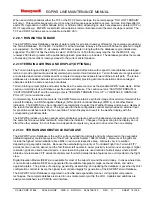
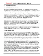
This manual is applicable to the MK V, MK VI, MK VII, MK VIII, and MK XXII EGPWS with the following part 
numbers and general description: 

MK V EGPWC PART NUMBERS 

MK VII EGPWC PART NUMBERS 

965-0976-003-XXX-XXX 

115 VAC, -40

°

 to +70

°


965-1076-001-XXX-XXX 

115 VAC, -40

°

 to +70

°


965-0976-020-XXX-XXX 

115 VAC, Internal 8 channel 
GPS, -40

°

 to +70

°


965-1076-020-XXX-XXX 

115 VAC, Internal 8 channel 
GPS, -40

°

 to +70

°


965-0976-040-XXX-XXX 

28 VDC, -55

°

 to +70

°


965-1076-030-XXX-XXX 

28 VDC, Internal 8 channel 
GPS, 55

°

 to +70

°


965-0976-060-XXX-XXX 

115 VAC, Integral GNSSU, 
-40

°

 to +70

°


965-1076-040-XXX-XXX 

28 VDC, -55

°

 to +70

°


965-1676-XXX (Airbus P/N) 

115 VAC, -40

°

 to +70

°


965-1076-060-XXX-XXX 

115 VAC, Integral GNSSU, 
-40

°

 to +70

°


965-1690-XXX (Boeing P/N) 

115 VAC, -40

°

 to +70

°


MK VI EGPWC PART NUMBERS  MK VIII EGPWC PART NUMBERS

MK XXII EGPWC PART NUMBERS

965-1176-XXX  28 VDC, -55

°

 to +70

°


965-1206-XXX 

28 VDC, -55

°

 to +70

°


965-1590-XXX 

28 VDC, Internal 8 channel 
GPS, -55

°

 to +70

°


965-1186-XXX 

28 VDC, Internal 8 channel 
GPS, -55

°

 to +70

°


965-1216-XXX 

28 VDC, Internal 8 channel 
GPS, -55

°

 to +70

°


965-1595-XXX 

28 VDC, Improved CPU, 
Internal 8 channel GPS, 
-55

°

 to +70

°


965-1180-XXX 

28 VDC, Improved CPU, 
-55

°

 to +70

°


965-1210-XXX 

28 VDC, Improved CPU, 
-55

°

 to +70

°


965-1190-XXX 

28 VDC, Improved CPU, 
Internal 8 channel GPS, 
-55

°

 to +70

°


965-1220-XXX 

28 VDC, Improved CPU, 
Internal 8 channel GPS, 
-55

°

 to +70

°


TABLE 1-1  EGPWC Part Numbers 

NOTE:

 X’s represent variable values defining a specific application and configuration software version (i.e., -230-230 for MK V/VII 

or -011 for MK VI/VIII/XXII original model or -026 for MK VI/VIII/XXII with improved CPU). 


Summary of Contents for MK V

Page 1: ...IZE A DWG NO 060 4199 180 REV G SHEET 1 of 68 MK V MK VI MK VII MK VIII MK XXII Enhanced Ground Proximity Warning Systems Line Maintenance Manual Document No 060 4199 180 Rev G Release date 29 Mar 2010 Honeywell International Inc Redmond Washington 98073 9701 ...

Page 2: ...are the property of Honeywell and is provided to the recipient in confidence on a need to know basis Your use of this document is strictly limited to a legitimate business purpose requiring the information contained therein Your use of this document constitutes acceptance of these terms Typed signatures constitute approval Actual Signatures are on file at Honeywell in Redmond WA DRAWN R Halbert 23...

Page 3: ...tion Software Version Invalid and RCD Failed MK V VII aural annunciations to Table 3 2 3 Sections 3 8 42 and 3 8 43 4 Appendix C Reason 01 Severity 10 08 JAN 04 09 JAN 04 J Castro L Matter All D 1 Deleted Revisions Status of Sheets Index table on Sheet 3 2 Section 3 2 Troubleshooting Guide Added the statement this sentence does not apply to internal GPS engines after the existing sentence If no fa...

Page 4: ...ified step 6 to add Level 3 Self Test Reason 01 Severity 10 01 FEB 05 03 FEB 05 S Wright K Christofferson All F Updated per ECO 65820 Updated document to include MK XXII helicopter EGPWS and to include software 230 230 changes for RAAS and newly introduced optional functions for Stabilized Approach Monitor Long Landing Monitor Altimeter Monitor and Takeoff Flap Configuration Monitor EFF PT 10 23 J...

Page 5: ...2 2 15 Runway Awareness and Advisory System option for MK V and MK VII only 17 2 2 16 Stabilized Approach Monitor option for MK V and MK VII only 17 2 2 17 Altimeter Monitor option for MK V and MK VII only 17 2 2 18 Takeoff Flap Configuration Monitor option for MK V and MK VII only 18 2 2 19 Long Landing Monitor option for MK V and MK VII only 18 2 2 20 Low Airspeed Monitor MK V Boeing 737NG only ...

Page 6: ...tric Altitude Rate Validity Discretes 46 3 8 29 Acceleration Self Test In Progress Discrete 46 3 8 30 Longitudinal Acceleration Validity Discrete 46 3 8 31 46 3 8 32 Normal Acceleration Validity Discrete 46 3 8 33 Magnetic Heading Validity Discrete 47 3 8 34 AOA Vane Heater Discrete 47 3 8 35 PLI Deselect Switch Discretes MK V and MK VII only 47 3 8 36 Autopilot Disconnect Discretes 47 3 8 37 Tact...

Page 7: ...DJUSTMENT 58 7 2 TEST 58 7 2 1 EGPWS Ground Tests 58 8 INSPECTION CHECK 59 8 1 GENERAL 59 9 CLEANING PAINTING 59 9 1 GENERAL 59 10 REPAIRS 59 10 1 GENERAL 59 11 APPENDIX A WINVIEWS 60 12 APPENDIX B TROUBLESHOOTING DO S AND DO NOT S 61 13 APPENDIX C RAAS MAINTENANCE MESSAGES AURAL DISPLAYED 62 14 APPENDIX D STABILIZED APPROACH MONITOR MAINTENANCE MESSAGES 64 15 APPENDIX E ALTIMETER MONITOR MAINTENA...

Page 8: ...GPS 40 to 70 965 0976 040 XXX XXX 28 VDC 55 to 70 965 1076 030 XXX XXX 28 VDC Internal 8 channel GPS 55 to 70 965 0976 060 XXX XXX 115 VAC Integral GNSSU 40 to 70 965 1076 040 XXX XXX 28 VDC 55 to 70 965 1676 XXX Airbus P N 115 VAC 40 to 70 965 1076 060 XXX XXX 115 VAC Integral GNSSU 40 to 70 965 1690 XXX Boeing P N 115 VAC 40 to 70 MK VI EGPWC PART NUMBERS MK VIII EGPWC PART NUMBERS MK XXII EGPWC...

Page 9: ...irport Coverage List MK V and MK VII 060 4353 000 EGPWS Terrain Database Obstacle Coverage Chart MK VI MK VIII MK XXII 965 1176 601 Product Specification for the MK VI and MK VIII EGPWS original model 965 1180 601 Product Specification for the MK VI and MK VIII EGPWS with improved CPU 965 1590 601 Product Specification for the MK XXII EGPWS original model 965 1595 601 Product Specification for the...

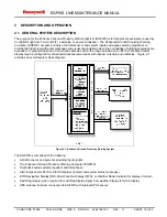
Page 10: ... terrain and obstacles within the range selected on an EFIS or Weather Radar display may be configured for enhanced situational awareness with respect to terrain and obstacles Figure 2 1 provides an overall system block diagram Figure 2 1 Enhanced Ground Proximity Warning System The EGPWS is comprised of the following Aircraft sensors and systems providing input signals The Enhanced Ground Proximi...

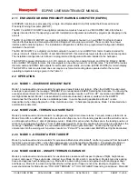
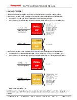
Page 11: ...minate Continuing the excessive descent rate into the EGPWS warning alert envelope results in a PULL UP enunciation and EGPWS alert lights illuminated Mode 1 is desensitized to eliminate unwanted nuisance alerts when the EGPWS determines that the aircraft is above a Glideslope beam In some fixed wing applications Mode 1 is also desensitized when Steep Approach or Flap Override is active In helicop...

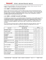
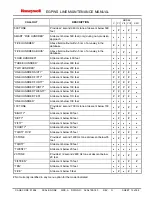
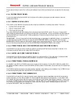
Page 12: ...isory Callouts are defined and enabled in the installation configuration If Altitude Callouts are not enabled only DH based MINIMUMS callouts will be provided The MK XXII offers a tail strike advisory for helicopters Only aural callouts are provided for Mode 6 EGPWS alert lights are NOT illuminated for Mode 6 callouts The following table identifies all of the Mode 6 Callouts that are available and...

Page 13: ...FTY At descent below 150 feet ONE HUNDRED FORTY At descent below 140 feet ONE HUNDRED THIRTY At descent below 130 feet ONE HUNDRED TWENTY At descent below 120 feet ONE HUNDRED TEN At descent below 110 feet ONE HUNDRED At descent below 100 feet 100 TONE Provides 2 second 700 Hz tone at descent below 100 feet EIGHTY At descent below 80 feet SIXTY At descent below 60 feet FIFTY At descent below 50 fe...

Page 14: ...AR WINDSHEAR WINDSHEAR with a corresponding cockpit warning light annunciation 2 2 8 ENVELOPE MODULATION NOT AVAILABLE IN MK VI VIII 001 Envelope Modulation provides improved alert protection and expanded alerting margins at identified key locations throughout the world Due to terrain features at or near certain specific airports normal operations have resulted in nuisance or missed alerts at thes...

Page 15: ...so maintains a synthetic image of local terrain forward of the aircraft for display on EFIS Navigation Displays ND s Multi Functional Displays MFD s or Weather Radar Indicators The EGPWS may be configured to automatically de select the Weather Display and pop up a display of the terrain threats when they occur The logic used for these configurable controls also provides an external input for predi...

Page 16: ...low the aircraft is not displayed typically leaving the terrain display blank during the enroute portion of flight The Peaks Mode Display adds additional density patterns and level thresholds based on terrain elevations relative to the range and distribution of terrain in the display area The Peaks Mode is thus a merged display applicable to all phases of flight Within the Peaks Mode display two e...

Page 17: ...rotection and operation is unaltered by the addition of RAAS RAAS installation is accomplished via a configuration database upload The installation does require that the EGPWS has a source of GPS data software 218 218 or 002 or 051 or later Terrain Database version 435 or later 454 or later if using software 230 230 or later and the RAAS Configuration Database RCD or Reloadable Customer Definition...

Page 18: ...nt safety enhancements for aircraft equipped with Honeywell s MK V or MK VII Enhanced Ground Proximity Warning Systems EGPWS Honeywell s Long Landing Monitor is a software enhancement hosted in the EGPWS Unit Long Landing Monitor uses GPS position data and the Honeywell EGPWS Database to provide aural alerts that supplement flight crew awareness of their position during a landing when the aircraft...

Page 19: ...s except windshear and Mode 6 callouts will activate the caution lamp output amber Note Actual legends may vary EGPWS caution or warning alerts lamp driver outputs are activated for all Mode 1 5 GPWS alerts and Terrain or Obstacle alerts when enabled Windshear warning and caution alerts activate separate lamp outputs when enabled Modes 1 4 TA Mode 5 only AMBER SINK RATE SINK RATE PULL UP TERRAIN T...

Page 20: ...database region This is indicated by the TERR INOP or NOT AVAILABLE status indicator and the loss of terrain display when enabled and active 2 3 3 BIT DESCRIPTION The EGPWC contains an extensive BIT capability The BIT functions provide high confidence that the Warning Computer and interface signal sources are operating properly and that the EGPWS will perform its intended function Detected failure...

Page 21: ...uter Fail condition 2 3 4 2 FRONT PANEL SELF TEST INTERFACE MK V AND MK VII ONLY The EGPWC front panel provides a Self Test switch for activating Self Test features described in Section 2 3 5 This switch functions the same as cockpit Self Test switches 2 3 4 3 AUDIO JACK MK V AND MK VII ONLY The EGPWC front panel provides a headphone jack for use during Self Test The audio jack is a standard 600Ω ...

Page 22: ...evel 1 Identifies the status of each of the major functions of the EGPWS This is the normal pre flight test performed by the flight crew Level 2 Identifies all failures currently within the system Level 2 is accessed by maintenance personnel to help resolve INOP conditions Level 3 Identifies the configuration status of the Warning Computer and the installation Level 4 Identifies faults that have o...

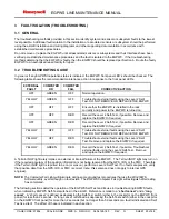
Page 23: ... Level 2 Self Test if possible Remove and replace the EGPWC if required YELLOW OFF OFF Troubleshoot external faults using the Level 2 Self Test DO NOT REMOVE OR REPLACE THE EGPWC YELLOW OFF RED Troubleshoot external faults using the Level 2 Self Test Remove and replace the EGPWC if required YELLOW GREEN RED Record the Level 2 Self Test if possible Troubleshoot external faults using the Level 2 Sel...

Page 24: ...figuration type is not a valid configuration Action Correct and reprogram the Configuration Module see Maintenance Practices section Enunciation AIRCRAFT CONFIGURATION DATA BASE FAILED MK V or MK VII only Probable Cause EGPWC internal Configuration database error Action Pull power to the EGPWS for one minute and cycle power to clear all potential faults before removing or replacing the EGPWC for r...

Page 25: ...le and activates system outputs The short Level 1 Self Test is a subset of the Long Level 1 Self Test Upon successful completion of the preamble the short Self Test is started A Short Level 1 Self Test sequence following the Preamble is as follows GPWS INOP Windshear INOP Terrain INOP or Terrain Not Available lights turn on Amber caution GPWS or Below G S lights turn on Voice GLIDESLOPE Amber caut...

Page 26: ...g Level 1 Self Test enunciates all configured and activated alert voices including warning voices caution voices and altitude callout voices immediately following the Short Level 1 Self Test sequence above 3 4 LEVEL 2 SELF TEST CURRENT FAULTS Level 2 Self Test provides enunciation of all faults existing at the time of the test request Level 2 Self Test is initiated by pressing Self Test within 3 s...

Page 27: ... GPS FAILED APPLICATION SOFTWARE VERSION INVALID RCD FAILED MK V VII Probable Cause EGPWC failure Action Remove and replace the EGPWC Notes If external faults also exist these should be eliminated and the internal faults rechecked before the EGPWC is removed and replaced Power unit on bench with parity pin strapped and verify the failure is cleared If the EGPWC incorporates the integral Mercury GN...

Page 28: ...with an airspeed 250 knots or indicates Not Landing Flaps for more than 2 seconds with Too Low Flaps message below 100 feet GEAR SWITCH FAULT Indicates Landing Gear for 60 seconds with an airspeed 290 knots or indicates Not Landing Gear for more than 2 seconds with Too Low Gear message below 100 feet AUDIO CANCEL INVALID Discrete selected for 30 seconds TERRAIN INHIBIT INVALID Discrete selected fo...

Page 29: ...ted no connection from the source LRU Action Verify wiring from the source LRU Enunciation FLAP SWITCH FAULT Probable Cause Electrical short at the flap discrete input Action Verify wiring from the flap override switch and or flap input discretes Enunciation GEAR SWITCH FAULT Probable Cause Electrical short at the gear discrete input Action Verify wiring from the gear override switch and or gear i...

Page 30: ... XX is a number Probable Cause Invalid option selected Action Verify wiring to all program pins Description CONFIGURATION MODULE READ ERROR WinVIEWS ONLY Probable Cause The Configuration Module is faulty Action Cycle power to EGPWC If fault persists reprogram or replace the Configuration Module Description CONFIGURATION MODULE NOT PROGRAMMED WinVIEWS ONLY Probable Cause The Configuration Module is...

Page 31: ... SHEET 31 of 68 TABLE 3 5 GENERAL FAILURE CODE IDENTIFIERS For example if the Computed Airspeed from Air Data Computer 1 is failed i e SSM Fail Warning the following messages would be enunciated CURRENT FAULTS EGPWC OK EXTERNAL FAULTS AIR DATA BUS 1 COMPUTED AIRSPEED FAULT PRESS TO CONTINUE ...

Page 32: ... Deck TABLE 3 6 LEVEL 2 SELF TEST NAVIGATION STATUS MESSAGES THE FOLLOWING GPS STATUS MESSAGES ARE AVAILABLE IN LEVEL 2 SELF TEST Enunciation TERRAIN AWARENESS NO VALID LATITUDE Probable Cause GPS GNSSU has not acquired a sufficient number of satellites Action Remove aircraft from hanger and wait 5 to 20 minutes for the GPS GNSSU acquire a sufficient number of satellites Verify cabling and antenna...

Page 33: ...ion Software Version only for PNs 965 0976 XXX or 965 1076 XXX 6 Terrain Database Version 7 Envelope Modulation Database Version 8 Boot Code Version 9 RAAS RCD Part Number MK V VII and RAAS enabled only 10 Aircraft Type 11 Audio Menu 12 Altitude Callout Menu 13 All other selected options from installation configuration Note that only those features that are enabled or disabled from the basic confi...

Page 34: ...TRIPLE RA SELECTED WINDSHEAR DISABLED WINDSHEAR INOP DISABLED SIM REPOSITION ENABLED BANK ANGLE DISABLED ALTERNATE RA 1 SELECTED ALTERNATE RA 2 SELECTED ALTN GPS BUS SPEED SELECTED PWS OPTION 1 SELECTED PWS OPTION 2 SELECTED ALTERNATE POP UP SELECTED BANK ANGLE OPTION 1 SELECTED BANK ANGLE OPTION 2 SELECTED CONFIGURATION OPTION 1 SELECTED CONFIGURATION OPTION 2 SELECTED ALTERNATE MODE 4B REV SELEC...

Page 35: ...K XXII INHIBIT ALL EXCEPT MINIMUMS TYPE CALLOUT SELECTED MK XXII INHIBIT TOO LOW GEAR SELECTED MK XXII INHIBIT RUNWAY CALLOUTS 50 AND BELOW SELECTED MK XXII ALTERATE DECISION HEIGHT SELECTED MK XXII RUNWAY AWARENESS ENABLE SET OR RUNWAY AWARENESS ENABLED APPROACH MONITOR ENABLED FLAPS MONITOR ENABLED ALTIMETER MONITOR ENABLED LONG LANDING ENABLED AIRSPEED LOW INHIBITED Ensure that none of these ma...

Page 36: ...iated for proceeding to Level 5 Self Test TABLE 3 8 LEVEL 4 SELF TEST INFORMATION THE FOLLOWING INFORMATION IS GIVEN IN THE LEVEL 4 SELF TEST 1 Enunciate the number of the most recent flight leg with faults as FLIGHT X where X is a number from 1 to 10 where 1 is the most recent flight leg 2 Enunciate any internal faults stored for leg X 3 Enunciate any external faults stored for leg X 4 Increment ...

Page 37: ...NUE 3 8 LEVEL 6 SELF TEST DISCRETE INPUT TEST Level 6 Self Test provides enunciation of any changes in the status of discrete inputs for verification proper function and discrete input wiring Level 6 Self Test is initiated by pressing the cockpit Self Test button within 3 seconds of the end of Level 5 Self Test The results are indicated in the following sections If a state change occurs on any dis...

Page 38: ...Landing Gear Down or Landing Gear Up Fault monitoring Indication of landing gear selected for more than 60 seconds at airspeeds above 290 knots will result in a gear switch fault which will cause a GPWS INOP indication Note This can be caused either by a gear switch fault or by the Gear Override switch being left in the on position Level 6 Audio readout Landing Gear Discrete or Gear Override Selec...

Page 39: ... the Audio readout will be Level 6 Audio readout GND Landing Flaps Discrete or Flap Override Selected Not Selected Flaps Selected Flaps Not Selected 3 8 5 28V LANDING FLAP OR FLAP OVERRIDE DISCRETE Type Supplied by Flap or Flap selector handle switch This input can be paralleled with or used exclusively by a Flap Override Switch if an alternate source of Flap Position is used Signal Status Landing...

Page 40: ...TEST DISCRETE Type Supplied by momentary actuated cockpit self test switch Signal Status Self Test or Normal Fault monitoring Activation of this input continuously for more than 60 seconds will result in the Self Test Invalid fault which will cause a GPWS INOP indication Note This input is used to start and stop the Level 6 Self Test there is no audio output for this discrete in Level 6 3 8 8 STEE...

Page 41: ... ILS Tuned ILS Not Tuned ILS 2 Tuned ILS 2 Not Tuned 3 8 10 28V ILS TUNED DISCRETE Type Supplied by ILS VOR Mode Selector Signal Status ILS tuned or VOR tuned Level 6 Audio readout 28 V ILS Tuned Discrete 1 ILS Tuned ILS Not Tuned 28V ILS 1 Tuned 28V ILS 1 Not Tuned 28 V ILS Tuned Discrete 2 ILS Tuned ILS Not Tuned 28V ILS 2 Tuned 28V ILS 2 Not Tuned 3 8 11 GLIDESLOPE VALIDITY DISCRETES Two Glides...

Page 42: ...ary test if inhibited Level 6 Audio readout 28V Glideslope Inhibit Discrete Inhibit Not Inhibit 28V Glideslope Inhibit True 28V Glideslope Inhibit False 3 8 14 GND GLIDESLOPE CANCEL DISCRETE Type Supplied by momentarily actuated cockpit Glideslope mode manual inhibit switch Signal Status Glideslope is canceled if glideslope function is active Fault monitoring Activation of this input for more than...

Page 43: ...odes Inhibit fault which will cause GPWS and Terrain INOP indications As a function of selected aircraft type this discrete can also cause the All Modes Inhibit fault after 60 seconds even if it is only configured to suppress audio Type Analog discrete input from a flight deck mounted switch Signal Status Audio Suppress enabled or disabled All Modes Inhibit enable or disable Level 6 Audio readout ...

Page 44: ...dio readout Display Select Discrete 1 True False Display Discrete 1 True Display Discrete 1 False Display Select Discrete 2 True False Display Discrete 2 True Display Discrete 2 False 3 8 22 TERRAIN AWARENESS TCF INHIBIT Type Switch for inhibit of Terrain Awareness TCF functions Signal Status Terrain Awareness TCF Inhibit or Not Inhibit Terrain Inhibited will be enunciated during cockpit Self Test...

Page 45: ...izer Validity Discrete 1 Valid Invalid Localizer 1 Valid Localizer 1 Invalid Localizer Validity Discrete 2 Valid Invalid Localizer 2 Valid Localizer 2 Invalid 3 8 26 ATTITUDE VALIDITY DISCRETES Two Attitude validity discretes may be used by EGPWS one for each possible Attitude sensor Type Validity from Attitude sensor Signal Status Valid or Invalid Level 6 Audio readout Attitude Validity Discrete ...

Page 46: ...ation sensor Signal Status Acceleration Self Test Active or Inactive Level 6 Audio readout Acceleration Self Test In Progress In Progress Not in Progress Acceleration Self Test Active Acceleration Self Test Inactive 3 8 30 LONGITUDINAL ACCELERATION VALIDITY DISCRETE Longitudinal Acceleration validity discrete may be used by EGPWS for the Acceleration sensor Type Validity from Acceleration sensor S...

Page 47: ...A Vane Heater Off 3 8 35 PLI DESELECT SWITCH DISCRETES MK V AND MK VII ONLY PLI deselect switch discretes may be used by EGPWS for de activating the PLI select relays to remove EGPWS PLI indication from the ADI Type momentary make break switch Signal Status EGPWS PLI deselected Level 6 Audio readout PLI Deselect Switch 1 Pressed Not Pressed PLI Deselect Switch 1 True PLI Deselect Switch 1 False PL...

Page 48: ...titude Alert Selected or Deselected Level 6 Audio readout Altitude Alert Discrete True False Altitude Alert Selected Altitude Alert Deselected 3 8 39 CORRECTED BAROMETRIC ALTITUDE VALIDITY DISCRETE Corrected Barometric Altitude Validity Discrete may be used by EGPWS to determine when the Corrected Altitude input is invalid Type Validity from Corrected Barometric Altitude computer Signal Status Val...

Page 49: ...sabled Fault monitoring Activation of this input for more than 5 seconds will result in the GPWS Inhibit fault which will cause a GPW INOP indication Level 6 Audio readout GPWS Inhibit Discrete GPWS Inhibit Not Inhibit GPWS Inhibit GPWS Not Inhibit 3 8 43 RAAS ENABLE DISCRETE MK V AND MK VII ONLY Type Discrete for enabling RAAS functionality Signal Status RAAS Enabled or Disabled Level 6 Audio rea...

Page 50: ...6 STABILIZED APPROACH MONITOR INHIBIT DISCRETE MK V AND MK VII ONLY Type Discrete for inhibiting Stabilized Approach Monitor functionality Signal Status Approach Monitor Inhibit or Not Inhibit Level 6 Audio readout Stabilized Approach Monitor Inhibit Discrete True False Approach Monitor Inhibit Approach Monitor Not Inhibit 3 8 47 LOW AIRSPEED MONITOR INHIBIT DISCRETE MK V 737NG ONLY Type Discrete ...

Page 51: ...abases is addressed in a generic Service Bulletin EGPWS databases are not identified on the EGPWC nameplate as a part of the unit part number However for the MK V and MK VII there is a label on the inside of the front panel maintenance door that can be used for identifying the installed terrain database For the MK VI MK VIII and MK XXII a separate label is placed on the unit front panel identifyin...

Page 52: ...wnloading 4 3 2 DOWNLOAD PROCEDURE 1 For the MK VI MK VIII and MK XXII access and connect Smart Cable p n 951 0386 001 to Test Connector J3 on the EGPWC front panel For the MK V or MK VII access and open the front panel door on the EGPWC 2 Apply power to the EGPWC 3 Verify that the COMPUTER OK LED is ON NOTE If the COMPUTER FAIL LED is ON the integrity of the Downloaded Data cannot be assured NOTE...

Page 53: ... and pull from the Smart Cable NOTE The EGPWS should automatically return to its normal operating mode upon removal of the card 10 Verify that the COMPUTER OK LED illuminates allow up to 3 minutes for the light to come on 11 Procedure is complete Close the EGPWC front panel door or disconnect the Smart Cable as appropriate NOTE Flight History Download Cards can only be used once 4 3 3 TRANSCRIPTIO...

Page 54: ...e chosen ID for the associated category with the first being category 1 and the last being category 15 in order The following slash indicates the end of the data Note If 15 ID s don t follow 15 the error message Invalid Parameter Not enough category ID s Configuration update failed please try again will be given The value entered for each category must be an available ID for the associated categor...

Page 55: ...to example 92 T or F is True or False for rebooting the EGPWC Use T if only one category is to be changed and the EGPWC will reboot following ENTER Use F if another individual ID is to be changed by another CAT operation Example CFG CAT 7 92 T 5 After inputting the desired change information pressing ENTER will transmit the data to the EGPWC to write to the Configuration Module If a reboot is comm...

Page 56: ...eaks Mode Enable True Obstacle Awareness Enabled True Bank Angle Enable True Flap Reversal True GPS Altitude Reference MSL required for internal GPS source Cat 3 ID 2 Category 8 Radio Altitude Input Select 1 Category 9 Navigation Input Select 0 Category 10 Attitude Input Select 0 Category 11 Heading Input Select 0 Category 12 Windshear Select type 0 Category 13 Discrete I O Type Select 0 Category ...

Page 57: ...Test per Section 3 3 to verify EGPWC operation 6 If RAAS or any other optional function is installed refer to Level 1 and Level 3 Self Test messages in Appendix C through G to validate the RCD version installed 6 2 CONFIGURATION MODULE MK VI MK VIII AND MK XXII ONLY Refer to the appropriate Installation Design Guide referenced in Section 1 3 for Configuration Module illustrations 6 2 1 REMOVAL 1 R...

Page 58: ... Access and remove the display switching relay s using standard maintenance practices 6 3 2 INSTALLATION 1 Ensure that EGPWC Weather Radar and display switching relay power is removed 2 Mount relay s and secure 3 Provide power to the EGPWC and all required sensors and subsystems 4 Provide power to the Weather Radar system 5 Provide power to the display switching relays 6 Perform a Level 1 Self Tes...

Page 59: ...tine aircraft maintenance inspections 9 CLEANING PAINTING 9 1 GENERAL The EGPWS does not contain any elements that required cleaning or painting on the aircraft Any cleaning or painting of the EGPWC should be performed by an authorized EGPWS repair facility 10 REPAIRS 10 1 GENERAL No on aircraft repairs are identified for the EGPWS If a problem is found with a unit remove and replace the unit per ...

Page 60: ... addition to the WinVIEWS software a command file may be utilized The command file is a simple text file that includes each Current Value Table CVT Item used in a test procedure The file must be text only such as those created in the Microsoft Windows NotePad program It should have a filename extension of wvc or cmd The webpage mentioned above also contains generic command files for use in ground ...

Page 61: ...er to look at the front panel LEDs Green Computer OK LED means don t remove Amber External Fault LED means don t remove Red Computer means possibly remove DO NOT use cockpit INOP lamps for troubleshooting INOP indications are merely a pilot s indication of which EGPWS functions are inactive they are not positive indication of internal EGPWS faults Experience shows External non EGPWS faults are res...

Page 62: ...ction or the aircraft is at airport that has not been validated in the EGPWS Terrain Database Self Test Level 1 Runway Awareness Inhibited RAAS enabled but the advisories have been inhibited with the activation of an external input switch Self Test Level 1 Runway Awareness INOP RAAS enabled but the function is inoperative Self Test Level 1 Runway Awareness R T O RAAS enabled and functioning but RA...

Page 63: ...ated in Feet RAAS enabled functioning has good position information and is at a validated airport Distances annunciated in Metres RAAS N AVBL amber RAAS enabled but the system either has no position information the accuracy of the position information is insufficient to allow RAAS to function or the aircraft is at airport that has not been validated in the EGPWS Terrain Database last item only app...

Page 64: ...pproach Monitor enabled but the function is inoperative Self Test Level 2 Approach Monitor Approach Speed Undefined Stabilized Approach Monitor Too Fast function is enabled but the aircraft does not provide a source of Approach Speed Self Test Level 3 Annunciated at end of Selected Options Approach Monitor Enabled RCD Enable Key is set and loaded RCD activates Stabilized Approach Monitor function ...

Page 65: ...but the aircraft does not provide a source of GPS Self Test Level 2 Altimeter Monitor Static Air Temperature Undefined Altimeter Monitor function is enabled but the aircraft does not provide a source of SAT Self Test Level 3 Annunciated at end of Selected Options Altimeter Monitor Enabled RCD Enable Key is set and loaded RCD activates Altimeter Monitor function Self Test Level 3 RCD Part Number XX...

Page 66: ...o inhibit Takeoff Flap Configuration Monitor Self Test Level 1 Flaps Monitor INOP Takeoff Flap Configuration Monitor enabled but the function is inoperative Self Test Level 2 Flaps Monitor Flap Angle Undefined Takeoff Flap Configuration Monitor function is enabled but the aircraft does not provide a source of Flap Position Self Test Level 3 Annunciated at end of Selected Options Flaps Monitor Enab...

Page 67: ...he activation of an external input switch NOTE the EGPWS does not support a dedicated Long Landing Monitor inhibit but activation of a defined RAAS inhibit will also inhibit Long Landing Monitor Self Test Level 3 Annunciated at end of Selected Options Long Landing Enabled RCD Enable Key is set and loaded RCD activates Long Landing Monitor function Self Test Level 3 RCD Part Number XXX XXXX XXX whe...

Page 68: ...has all required input information Self Test Level 1 Airspeed Low Inhibited Low Airspeed Monitor enabled but the advisory have been inhibited via aircraft wiring Self Test Level 1 Airspeed Low INOP Low Airspeed Monitor enabled but the function is inoperative Self Test Level 3 Annunciated at end of Selected Options Airspeed Low Inhibited Low Airspeed Monitor enabled but the advisory have been inhib...

Reviews: