EGPWS LINE MAINTENANCE MANUAL
CAGE CODE: 97896
SCALE: NONE SIZE: A
DWG NO.: 060-4199-180
REV: G
SHEET 14 of 68
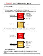
2.2.6.1 EXCESSIVE BANK ANGLE CALLOUT
The Bank Angle Callout feature provides callout enunciation for excessive bank angles based on altitude and bank
angle limits defined by aircraft type. It is intended to enhance situational awareness during intentional or
unintentional maneuvering, and for protection against wing or engine strikes when close to the runway.
When the bank angle limit is reached, the aural callout “BANK ANGLE, BANK ANGLE” is given. Follow-on aural
messages are only provided when the aircraft roll angle increases an additional 20% from the previous callout.
Bank Angle Callouts are enabled by the installation configuration.
2.2.6.2 TAIL STRIKE CALLOUT
A tail strike alert function is provided by the MK XXII for applicable rotary wing aircraft based upon Radio Altitude,
Pitch Attitude, Pitch Rate and Barometric Altitude Rate. The voice message “Tail Too Low “ is provided continuously
while within the alert boundary. Unique alert boundaries are provided for applicable aircraft types.
2.2.7 MODE 7 - WINDSHEAR DETECTION (OPTIONAL FOR MK V/VII ONLY)
Mode 7 provides the flight crew with visual and aural alerts for windshear of sufficient magnitude to be potentially
hazardous to the aircraft. The system is capable of detecting severe decreasing performance shears (i.e.
increasing tailwind/decreasing headwind and/or downdraft) which present an immediate danger to the aircraft. The
system is also capable of detecting severe increasing performance shears (increasing headwind/decreasing tailwind
and/or up draft). While these shears may not present an immediate danger to the aircraft, these shears can indicate
that the atmospheric instability is such that an encounter with a severe decreasing performance shear is likely.
A detected increasing performance shear will result in an aural “CAUTION WINDSHEAR” enunciation and cockpit
light annunciation when enabled. A detected decreasing performance shear will result in an aural siren followed by
“WINDSHEAR, WINDSHEAR, WINDSHEAR” with a corresponding cockpit warning light annunciation.
2.2.8 ENVELOPE MODULATION (NOT AVAILABLE IN MK VI/VIII -001)
Envelope Modulation provides improved alert protection and expanded alerting margins at identified key locations
throughout the world. Due to terrain features at or near certain specific airports, normal operations have resulted in
nuisance or missed alerts at these locations in the past. With the introduction of accurate position information and a
terrain and airport database, it is now possible to identify these areas and adjust the normal alerting process to
compensate for the condition.
Modes 4, 5, and 6 are expanded at certain locations to provide alerting protection consistent with normal
approaches. Modes 1, 2, and 4 are desensitized at other locations to prevent nuisance alerts that result from
unusual terrain or approach procedures. In all cases, very specific information is used to correlate the aircraft
position and phase of flight prior to modulating the envelopes. This function is automatic and transparent to crew
operation.
2.2.9 TERRAIN CLEARANCE FLOOR AND RUNWAY FIELD CLEARANCE FLOOR
The Terrain Clearance Floor (TCF) alerting function adds an additional element of protection to the standard Ground
Proximity Warning System for fixed-wing aircraft. It creates an increasing terrain clearance envelope around the
airport runway to provide CFIT protection against situations where Mode 4 provides limited or no protection. TCF
alerts are based on current aircraft location, destination runway center point position, and Radio Altitude (altitude
AGL). TCF is active during takeoff, cruise, and final approach. TCF complements the existing Mode 4 protection by
providing an alert based on insufficient terrain clearance even when in landing configuration.
The TCF function is enhanced in all fixed-wing models (beginning with release –210-210 for the MK V/VII) with the
addition of a Runway Field Clearance Floor (RFCF) alerting function. RFCF is based on current aircraft location,
destination runway center point position, and Geometric Altitude or altitude Above Sea Level (ASL) relative to the
destination runway. RFCF provides short landing protection for runways that are significantly higher than the
surrounding terrain.

