background image

51 

3

1

2

3

4

5

5

6

7

8

1

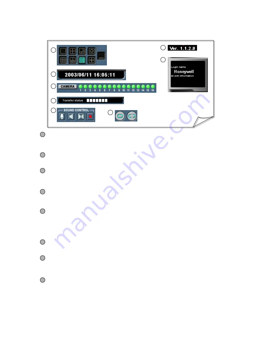
[Split Screen/Manual Switching/Full Screen/Minimized Screen]

Allows you to display the selected video image on 1, 4, 6, 9, 10, or 16 split screen. 

Allows you to display images with Manual Switching, Full Screen, and Minimized Screen. 

2

[System Data/Time Display]

Displays the date and time of the system on which 

HNDR-Net is installed. 

[Login/Event Information Display]

Login name: Displays the name of HNDR-Net user who is connected to the system on which 
HNDR is installed. 

Event information: Displays the type of event (motion or sensor) by which the HNDR system 
executed HNDR-Net automatically.

4

[Transfer Status Display]

Transfer status: Indicates the state of connection with HNDR. Moving fast indicates fast data 
transfer, and moving slowly indicates slow data transfer. 

5

[Camera Status Display]

Displays the status of HNDR cameras when connecting to the HNDR system. You may choose 
not to receive images from each camera by clicking on the camera status display. 

2-Way voice communication with HNDR (2 WAY Audio)

You can send and receive voice, establish 2-way voice communication, or cancel. 

• “

Voice Recording

should be selected on HNDR Setup (System Setup). 

[Sound Control]

6

[Connect/Non-Connect Control]

Allows you connect to or disconnect from HNDR-Net.

8

7

[Version Display]

Displays the version of the HNDR-Net Program.

(Subject to change with version changes.)

Summary of Contents for HNDR series

Page 1: ......

Page 2: ...uctions are violated Caution Sign that warns injury or material loss or damage in case relevant orders or instructions are violated Following signs and explanations specify required precautions that should be taken Warning This is a Prohibition sign that should not be violated Violation could cause loss or damage of life and property Caution This is a Mandatory sign that should be implemented Viol...

Page 3: ...t There is a danger of fire or mechanical failure Do Not Use This Product Where There Are Propane Gas Gasoline or Other Flammable Gas and Dust There is a danger of explosion or fire Caution Do Not Clean with Benzene Thinner or Other Volatile Matter It could damage products Do Not Install in an Unstable Place Fall could cause an injury or failure Do Not Use or Keep This Product Where There are Stro...

Page 4: ...he product contact the store where you purchased the product or the agency instead of trying to disassemble it yourself In case of product malfunction due to a product failure turn off the PC and contact the store where you purchased the product This product does not operate when the power circuit breaker is lowered or during power outage ...

Page 5: ...ponsible For additional information required for installation and in case HNDR needs to be disassembled for upgrading of system functions or repair please request for technical assistance from where you purchased this product or the main office of Honeywell HNDR is the registered trademark of Honeywell Co Ltd Safe use of this product is guaranteed as the product successfully completed domestic EMI...

Page 6: ... Unstable Place Make sure that the HNDR is not installed in an unstable place shelf or table It can injure users or other people or damage the product 8 In Case HNDR Does Not Operate Properly In case an abnormal movement is detected during operation I e unusual noise smell or smoke stop the operation immediately cut off the power supply and contact the store where you purchased the product 9 Clean...

Page 7: ...tents Key OP Manual Mouse Keyboard HNDR Series Check that these materials are included when you open the box Should there be anything missing contact the dealer bought it from 6 CD Power Cable Rack Mounter ...

Page 8: ...HNDR 11 3 Glance of HNDR 14 Chapter 2 Monitoring 1 Main Monitoring 16 2 Monitoring Status 18 3 Monitor Controls 19 4 Shell Monitoring 22 7 Chapter 3 Search Replay 1 Single View Search Replay 23 2 Multi View Search Replay 26 3 Search Replay Controls 27 PART 1 HNDR Operation ...

Page 9: ...asic Setup for Camera 33 4 Camera Recording Schedule Setup 34 5 Camera Motion Image Setup 35 6 Camera Pan Tilt Setup 36 7 Sensor Setup 37 8 Auto Backup Setup 38 9 User Setup 39 2 Backup VIEWER 1 Manual Backup 3 Data Authentication 8 40 41 42 Chapter 5 Application ...

Page 10: ...oring 50 4 Local Search Mode 54 5 Remote Search Mode 56 6 HNDR Net Setup 58 Chapter 7 HNDR Web 9 PART 3 HNDR Web Operation 1 Connecting to HNDR Web 62 2 HNDR Web Monitoring 63 3 HNDR Web Settings 64 PART 4 Appendix Chapter 8 Appendix 1 Connecting other Hardware 66 2 Installing HNDR Net 69 3 Installing HNDR Web 70 Warranty 74 ...

Page 11: ...common QUAD VCR SWITCHER and MUX functions Keeping recorded data has been a tough task But the HNDR system makes it possible to keep data with various volumes semi permanently by recording them on up to date backup devices DAT CD DVD etc The HNDR system allows you to control security devices in connection with sensors and operate control devices automatically manually with ease In addition remote ...

Page 12: ...he system restoring it to the normal operational condition Recording with Motion and Sensor Detection A camera can record images only when it detects any motion It can also record images when it detects sensors Data monitoring and storage are made easy without storing unnecessary images Diverse Methods for Image Compression Transmission Available choices for compressing and transmitting images are...

Page 13: ...port allows you to remotely access the HNDR to retrieve or backup image data You can set up preferences on the HNDR as well 12 Specification Item RS 485 Interface PTZ CD DAT DVD Backup PSTN ISDN ADSL LAN HNDR Net Transmission Method Continuous Recording Sensor Recording Motion Recording Sensor Motion Recording Event Recording Recording Method Select MJPEG or MPEG Image Compression Method 1 Channel...

Page 14: ...he HNDR Net is available PAN TILT ZOOM FOCUS Remote Control Support Allows you to control PAN TILT equipment connected with the HNDR via the HNDR Net Control HNDR Preferences Allows you to set up HNDR preferences such as camera usage schedule management and sensor settings via the HNDR NET Receiving Automatic Notification via HNDR When something moves or sensors go off in the HNDR system a system ...

Page 15: ...uct Name Digital Video Recorder Product Logo Honeywell Logo Honeywell Logo 3 5 FDD Disk FDD CD RW DVD RW Option CD RW DVD RW CD ROM Removable HDD Rack Option CD ROM R HDD Rack Power Switch Power Switch Noise filter Filter HDD Status indicator Yellow Color HDD LED Abnormal Status indicator Green Color RUN LED Power Status indicator Red Color POWER LED 19 Rack Mount Rack Mount Function Item 1 2 3 4 ...

Page 16: ...ort Parallel Port USB port USB Port Keyboard port Keyboard Mouse port Mouse Composite signal output Extra Monitor Output Sensor In 16 Out 4 terminal Sensor In 16 Out 4 Camera Input 1 16 terminal Camera In 1 16 Power In Out Select Switch Power In Out Select Power Select switch 230 115V Power Select Power Input Power Input Power Fan Power Fan 1 2 3 4 5 6 7 8 9 10 11 12 13 14 15 16 17 18 19 10 11 12 ...

Page 17: ...Use them for search setup and Net access 1 Split Screen settings Select the 1 4 6 9 10 or 16 split button with the mouse to display images on the selected split screen Manual Switching Select the manual switching button with the mouse on the 1 4 6 9 or 10 split screen to switch manually and display images 2 Automatic Switching Select the automatic switching button with the mouse on the 1 4 6 9 10 ...

Page 18: ...e to display images on the selected split screen Manual Switching Select the manual switching button on the 1 4 6 9 or 10 split screen to switch manually and display images Automatic Switching Select the automatic switching button with the mouse on the 1 4 6 9 or 10 split screen to switch automatically and display images Monitor Screen Select the monitor screen button with the mouse to display the...

Page 19: ...ED lit in red indicates that images are being recorded by the camera A blinking red LED indicates that the camera is not connected yet after Camera enabled is selected on Setup A black LED indicates that images are not being recorded 3 4 5 6 Time Status Display Displays year month day and hour minute second of the HNDR Network Status Display Displays the access IP of the HNDR Net or Web connected ...

Page 20: ...dow to verify shell monitoring the HNDR When password authentication is verified the HNDR system is terminated with a buzzer sounding for about 1 minute and the system is re booted Please note that exiting will be not generated continuously unless Hot key is selected on shell monitoring Exit System 6 19 Displays the version of the HNDR program Version Display 7 7 8 Select the Control button with t...

Page 21: ...655 755 PTZ on Pan Tilt Settings of Setup to display the windows GC 655 755 Control 10 Moving Zoom In Out Focus In Out and Controlling Camera menu are available 11 Select HSDN 251 PTZ on Pan Tilt Settings of Setup to display the windows HSDN 251 Control 11 Moving 10 Pre positions is available 1 0 Monitoring 1 Auto scan zone is available Continuous monitoring 10 pre set pre positions is available T...

Page 22: ...SET UP the TOUR button of FUNCTION and the Preset button that you want to monitor consecutively among the set Preset buttons to complete the Tour Setup If 10 Presets are set in advance all 10 zones can be monitored consecutively but only 1 Tour function is possible Camera Menu Press the CAMERA MENU button of SET UP and the direction change buttons Enter ESC Up Down to set the camera Menu 1 1 P T S...

Page 23: ... Select the Main Monitoring icon with the mouse to display Monitoring screen Search Icon Select the Search Replay icon with the mouse to display single view search screen Setup Icon Select the Setup icon with the mouse to display setup of HNDR screen Application program Icon Select the Application icon with the mouse to display icon of Application program Authentication tool Backup tool Backup vie...

Page 24: ...n Allows you to shifting replay using the right button of mouse for multi screen 1 3 Search Date Selection Display Allows you to select a date to search with the mouse It also allows you to select a month to search A Red color Indicates where a video data recording date 3 Search Date GOTO Display Allows you to select a date to quick search with the GOTO button On this menu select time and date to ...

Page 25: ...led search 7 Adjust Replay Direction Allows you to adjust directions of replay videos and still pictures forward backward It also allows you to adjust the replay of first or last image in the selected time Hour Minute Display for Stored Data Displays information on stored images in single screen by hour and minute Display on the top represents the minute axis and the stored data are represented by...

Page 26: ...arch 11 Smart Replay list It indicates the No of image files searched by smart searching lists 12 Smart Replay It indicates the total No of image files searched by smart searching Allows you to adjust directions of replay videos and real pictures forward backward Skip Frame If you feel inconvenient in handling the huge stored data you can make the data file reduced to compact data file by skipping...

Page 27: ... multi screen It also allows you to select multi screen 4 6 9 16 with the mouse Allows you to shifting replay using the right button of mouse for single screen 1 2 Search Date Selection Display Allows you to select a date to search with the mouse It also allows you to select a month to search ...

Page 28: ...ODE window where you can adjust images of stored data Image Saving Select the SAVE AS button with the mouse to display a window where you can save the image being displayed in JPG format AVI Saving Select the AVI SAVE button with the mouse to display a window where you can save the images of the channel being displayed in AVI format Print Select the PRINT button with the mouse to display a window ...

Page 29: ...JPG format Saves an image displayed in Smart search mode as a file in BMP format When used MPEG compression Save file is made with BMP format file Formats other than JPG are not available for saving In Single search mode 5 AVI Saving Saves images of the channel displayed in single screen as a file in AVI format Selecting the SAVE button on the AVI SAVING window will start saving Clicking the CLOSE...

Page 30: ...vent system overload 2 System Setup Sets the settings for network access initial screen voice watch dog etc 3 Camera Setup Sets the default settings for camera recording schedule motion image and Pan Tilt etc 4 Sensor Setup Sets input output and interoperation of sensors 5 Backup Setup Sets an automatic backup schedule 6 User Setup Sets user name class permissions etc Caution 5 To apply and save s...

Page 31: ... and add volume set in the HNDR file system Volume Information Shows you the information on the total volumes assigned in the HNDR file system Total volume is the number of volumes assigned in the HNDR and the current volume is the number of volumes currently in use Disk Information Shows you the information on the disk in the HNDR file system Tips 1 What is Volume Volume refers to a unit in the H...

Page 32: ...Net be sure to record IP address of the HNDR system in IP Address Use IP Server Specially developed Program to control Dynamic IP Code The unique Code to be set in DVR instead of dynamic IP alphabet and numeric 5 digit IP Server IP server address Manage to address of HNDR HNDR Net IP Notify Interval Notify interval time 3 Screen Setup 4 Sound recording Check to record sound Audio device select Sel...

Page 33: ...From Specify an E mail address from which E mails will be sent If there is no specified E mail address E mails will be sent using the site name To Specify an E mail to which E mails will be sent Subject Enter the title of E mail Content Enter the content of E mail Send Interval Specify the time interval of E mails to be sent E mails are sent according to the specified Send Interval even if events ...

Page 34: ...ome out by detecting motion or sensor it goes off the beep sound When a video loss happen relay output 1 4 port relay output available Only remove from relay output on manually available Pre Saves as many images as specified from the previous image when motion or sensor occurs Post Saves as many images as specified after motion or sensor occurred 4 Pre Post Alarm Recording 5 Basic Setup Name Enter...

Page 35: ... HNDR Net system during the scheduled time zone or day of the week Available for Motion and Sensor setup only Setup Specify the desired time zone or day of the week Clear Deletes set schedules Specifying recording schedule by camera will enable saving images by day of the week and time zone Caution 8 Motion recording Set to Motion recording by default Recording motion occurs depending on the Motio...

Page 36: ...s 1 2 3 4 1 Motion detection area setting Whole area Select to monitor motion in all areas covered by the camera Partial area Allows you to monitor motion in specific areas by pressing the Add button and specify specific regions You may specify up to 20 areas and erase them by pressing Delete Display detected area Select and click the Detection test button to start monitoring the motions when it o...

Page 37: ...o connect start port and stop port 3 Speed setup P T F Z A P Allows you to control speed of Pan Tilt Focus Zoom and Auto pan 4 Auto Scan Preset setup Auto scan Allow you to control start point of Auto scan and stop point Press the Camera menu button and Auto scan button to enable setup HSDN 251 Preset Allow you to control preset 1 10 Press the Preset setup move preset position and press the preset...

Page 38: ... Output relay Verify the output relay port settings Latch time Verify the latch time settings Preset Verify the preset of ptz camera settings ex HSDN 251 2 Sensor input information Use sensor Select to use the sensor Sensor location Specify the location of the sensor Use 8 characters or less Sensor type Specify the sensor type N C N O Connected camera Specify the camera to connect Check time Set c...

Page 39: ...ff Verify the backup path settings 2 Select Backup Use schedule check to use automatic backup Camera selection Select cameras for backup 3 Backup Device Setup 4 Time setup 6 Select a day of the week for backup on the backup schedule table with the mouse Make sure that the backup day of the week has changed Allow you to use automatic start backup timer Scheduling 6 Backup setup completed When backu...

Page 40: ...with the mouse and press the Add Change buttons to add or change users You can set up up to 20 users 2 User name Name Enter the user name using 10 characters or less Password Enter the password using 10 characters or less Confirm password Reenter the password for confirmation 3 Security level 4 Use authority To add a user select the empty table in the user list and to change a user select the tabl...

Page 41: ...r When the backup setup is completed if you exit the program with Auto Startup checked and without executing the backup immediately the backup program will start backup automatically based on the settings next time it is executed Deletes all of settings for the backup process Starts backup in accordance with the settings Pressing the Backup Start button will open a dialog box to verify the drive a...

Page 42: ...arch backed up data and read data by date 6 Allows you to replay backed up data Each button represents Stop Replay Forward Still Replay Forward Start image in that order If stored sound data co exits by checking this Play with sound mode maybe viewing with sound performances 4 Data replay Allows you to save backed up data as still images in JPG format Allows you to print out backed up data as imag...

Page 43: ...ation that is using the HNDR system HNDR ID Computer ID Displays the HNDR ID Windows Serial ID Displays the unique serial ID of OS Resolution Displays the resolution status 2 Load Data Allows you to load the images to read If the images are genuine information for the images are displayed Otherwise it is displayed This is a program that determines whether the images stored by the Search Program or...

Page 44: ... on Login window Enter the login name description password confirm password on the New Login Registration window and click the OK button with the mouse Click New button with mouse on the Add Delete and Edit site information window Enter Site name Connecting method IP Tel address Site access user Site access password on the Site Information window and press the OK button Check if all the site infor...

Page 45: ...44 1 2 5 4 6 7 8 3 ...

Page 46: ...45 9 ...

Page 47: ...lit screen storage directory log file switching interval on screen display name display etc when connecting to HNDR Net Delete Current User Allows you to delete all existing login users For login use you should renew configuration settings See page 43 5 This window allows you to change settings for Site single or multiple connection initial screen etc after logging in the HNDR Net Program If you d...

Page 48: ... the site IP address or Tel number of the HNDR system Should be identical with the site address entered on page 30 Password Enter the password of the site that will connect to the HNDR system Should be identical with the password of the site entered on page 38 User name Enter the name of the site that will connect to the HNDR system Should be identical with the site address entered on page 38 OK C...

Page 49: ...stablishes a multiple site connection to the HNDR system Press the OK button to activate the multiple site connection window Connect on login Connection is established automatically on login Site name Select the site name to connect Camera number Select camera number from 1 to 16 and Partial or All When Partial is selected target camera is switched in order in accordance with automatic switching t...

Page 50: ...sition number of image Site name or Camera No Name Name display Select how the selected information should be displayed Use Always to display on screen display information all the time Use On mouse over to display on screen display mode information only when you move the mouse over the image screen Press the OK button to apply Use IP Server Set the IP Server for management of dynamic IP address Pl...

Page 51: ... IN ID and the login password on LOG IN P W and then press the LOGIN button to connect to the HNDR The following monitoring screen will be displayed Run the program by clicking the Honeywell Net icon on Desktop then the following Connect On Login window will be activated 1 ...

Page 52: ...uted HNDR Net automatically 4 Transfer Status Display Transfer status Indicates the state of connection with HNDR Moving fast indicates fast data transfer and moving slowly indicates slow data transfer 5 Camera Status Display Displays the status of HNDR cameras when connecting to the HNDR system You may choose not to receive images from each camera by clicking on the camera status display 2 Way vo...

Page 53: ... connected to HNDR Net Select either Saved while viewing or Saved while searching on the selected site and press the OK button to begin searching Saved while viewing allows you to search the data saved while viewing images on the HNDR Net system by pressing SAVE Saved while searching allows you to search the data saved by pressing Save during the search for the data saved in the HNDR while connect...

Page 54: ...OW SPEED lowers the transfer speed but enhances the image quality 16 COMP RATE Control Pressing the PTZ button activates PTZ CONTROL allowing you to control the Pan Tilt camera that is installed in HNDR by moving it upward downward to the left to the right or to diagonally as well as adjusting zoom and focus You can also set up camera selection using the camera selection button Allow you to contro...

Page 55: ...ws you to search the data saved in the system on which Honeywell Net is installed For site selection during local search select Saved while viewing or Saved while searching and press the OK button to begin searching data 1 2 3 4 ...

Page 56: ...calendar 4 Date Display 5 6 7 8 Press the SEARCH button to replay or search images Press the IMAGE MODE button to modify images Press the SELECT SITE button to display a list of the data of HNDR saved in other locations Press the SAVE AS button to save images being displayed Press the PRINT button to print images being displayed Press the AVI SAVE button to save data being searched in AVI format 5...

Page 57: ...e Search Mode 56 Allows you to search the data saved in the HNDR system on the Honeywell Net system Select the site name of the data saved in the HNDR system and press the OK button to begin searching 1 2 3 4 ...

Page 58: ...alendar 4 Date Display 5 6 7 8 Press the SEARCH button to replay or search images Press the IMAGE MODE button to modify images Press the SELECT SITE button to display a list of the data of HNDR saved in other locations Press the SAVE AS button to save images being displayed Press the PRINT button to print images being displayed Press the AVI SAVE button to save data being searched in AVI format 5 ...

Page 59: ...find out how to setup the HNDR on pages 37 Backup Setup Sets an automatic backup schedule See the figures shown on pages 61 Chapter 4 8 Auto backup setup to find out how to setup the HNDR on pages 38 Camera recording schedule setup Sets the recording schedule settings for camera remote notify schedule etc See the figures shown on pages 59 Chapter 4 4 Camera recording schedule setup to find out how...

Page 60: ...59 1 2 3 ...

Page 61: ...60 4 5 6 ...

Page 62: ...61 7 ...

Page 63: ...tton establishes the connection opening the following monitor screen Chapter 7 HNDR Web Chapter 7 HNDR Web 1 2 1 Connecting to HNDR Web Caution 12 Resolution Setting For a resolution of the user s PC lower than 1024 768 the standard button of the web browser should not be enabled A resolution higher than that demands no such requirement The Honeywell Web program is included either in the HNDR syst...

Page 64: ... button does not display images on the screen You may verify the name and IP of the site connected to the camera and the camera number by placing the mouse over the IP button 1 2 2 HNDR Web Monitoring 1 Split Screen Manual Switching Full Screen Setting Displays the selected video images on the 1 4 6 9 or 10 split screen Displays images on manual switching and full screen ...

Page 65: ...up window will be automatically closed immediately applying the information just entered to the HNDR Web monitor screen To delete the currently set items check the Del box and press the Save Apply button When you log in with the Administrator account User Select appears on the top allowing you to register or modify configurations for all registered users For guest accounts created for which guest ...

Page 66: ...er appropriate information in Name ID Password and Re type Password and press the Save button If you want to modify information on already registered users select user items to modify with the mouse from the user list in the center Information on selected users are displayed on each input window on the top Make necessary changes and press the Save button You can neither modify nor delete ID of adm...

Page 67: ...on connecting PTZ Pay attention to the polarity of signal lines Incorrect wiring combination may result in malfunction of the equipment Connect D SUB 9 Pin Port for connecting RS 485 attached to the PCI slot on the rear of the HNDR as shown below The D Sub 9 Pin Connector is provided 3 2 TX Data 1 TX Data Pin Number Pin Name RS 485 Connection 3 2 COM1 Serial communication cable S 2 S 1 Connect to ...

Page 68: ...3 4 5 6 8 7 10 9 12 14 11 15 S S Pink Rx Gray TX Brown Rx Violet TX CONT VIDEO POWER SVIDEO HNDR System GC 655 485 Type Connect D SUB 9 Pin Port for connecting RS 485 attached to the PCI slot on the rear of the HNDR as shown below The D Sub 9 Pin Connector is provided 4 4 ...

Page 69: ...lay Output 4 Channels Factory setting for control output access point is NC For controlled output access point is output if it is applied when its type is No Wiring Diagrams for External Sensor Input Relay Output Wiring Diagram for Sensor Input Wiring Diagram for Sensor Relay Output Caution 14 Notes on Using a Separate Power Supply for Sensor Input Relay Output Use an adapter for sensor input powe...

Page 70: ... Run setup exe and follow the instructions to complete the installation When HNDR Net Program is successfully installed confirm the HNDR Net folder on Desktop 2 Installing HNDR Net 69 1 5 6 1 6 2 4 3 5 ...

Page 71: ...1 2 3 4 70 3 Installing the HNDR Web Before installing the HNDR Web server Run Morgan exe Video Codec and follow the instructions 1 4 ...

Page 72: ...eb Publishing Service is set to be Started Or launch a web browser and enter http localhost in the address window to make sure that the IIS welcome page the default page appears successfully 3 Copying HNDR Web Files Copy HNDR Web files to the appropriate directory C HNDR Web files are included in the HNDR system or in the enclosed CD HNDR C Backup HNDR Honeywell HNDR PROGRAM HNDR Web CD CD HNDR Ho...

Page 73: ...72 A B C D E F G ...

Page 74: ...al Intranet if you access from a local server See D On Security level for this zone press Custom Level button at the bottom See E On the Security Settings window adjust ActiveX controls and plug ins See a b a b 3 HNDR Web Security Setting 4 Confirming the HNDR Web Program Launch a web browser and enter http localhost HNDR Web http Server Domain Name or IP Virtual Directory Name set on Item 3 in th...

Page 75: ...uct trying to repair it we may charge you with the fee q We don t support the breakage after warranty service period If the customer wants to get it repaired we charge them with the fee Product Warranty Service Sheet Ø This warranty sheet may not be provided again Ø Please get this sheet filled when you purchase the product Ø You should show this warranty service sheet when you get a warranty serv...

Page 76: ...82 2 799 6109 ...

Reviews: