2–2
2.2 REAR PANEL CONNECTORS
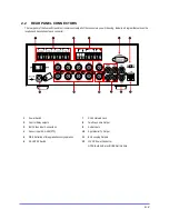
The rear panel of the Fusion Streamer unit contains virtually all of the connectors you will be using. Below is a diagram that outlines the
location and description of each connector:
1
Power Switch
7
RJ-45 Network Jack
2
Control Relay outputs
8
Two Way Audio Output
3
BNC Video Input Connections
9
Audio Inputs
4
Sensor Inputs/ RS-485 (PTZ)
10
Spot Monitor TV Output
5
DB-9 Serial Input for upgrade/recovery operation
11
BNC Looping Outputs
6
PAL/NTSC Switch
12
12V DC Power Connector
NOTE: Both AUX are UNUSED at this time
Summary of Contents for FUSION STREAMER
Page 1: ...Document 900 0600 10 05 Rev 1 00 Digital Video Transmission System User Guide FUSION STREAMER ...
Page 2: ......
Page 3: ...Revisions Issues Date Revisions 1 00 October 2005 Initial Release ...
Page 9: ......
Page 16: ......
Page 17: ......
Page 18: ......
Page 21: ...1 3 NOTES ...
Page 22: ...1 4 NOTES ...
Page 28: ...3 4 NOTES ...
Page 46: ...6 12 6 5 4 TIME CONFIGURATION Use this Menu to change the system time of the Fusion Streamer ...
Page 48: ...6 14 NOTES ...
Page 66: ...8 12 ...
Page 67: ...8 13 ...
Page 68: ...8 14 ...
Page 69: ......

