


Attention
•
If the Data Control Time and Watchdog Control Time are not configured properly, and there is a switchover
initiated, this may result in loss of communication with the slave devices. In such a scenario, you must modify
the Baud Rate, the Watchdog Control Time, and the Data Control Time. The Baud Rate is also dependent on
the number of slave devices configured in the network. In addition, you must select the
Override slave
specific Watchdog Control Time
check box.
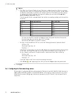
The following table lists the recommended baud rates and their corresponding watchdog control time and data
control time.
Baud Rate
Watchdog Control Time
Data Control Time
1500
1000
6000
500
1000
6000
187.5
2000
12000
93.75
3000
18000
45.45
4000
24000
19.2
5000
30000
9.6
6000
36000
– For devices that have DP-V1 enabled, the Watchdog Control Time and the Data Control Time must be
three times longer than the actual time when DP-V1 is disabled.
– By default, the ET200M devices have DP-V1 enabled.
•
When you select the Baud Rate as 45.45, the values of the following parameters are updated by default.
– Slot Time = 100
– Max. Station Delay Time = 60
– Setup Time = 1
The Siemens PA coupler supports only the 45.45 BR. Though they support the 45.45 BR, the default values of
the Slot Time, Max. Station Delay Time, and the Setup Time do not enable the coupler to detect the PA
devices. Therefore, when Siemens PA couplers are used, you must modify these values as following:
– Slot Time = 640
– Max. Station Delay Time = 400
– Setup Time = 95
The coupler can detect the PA devices only after modifying these values.
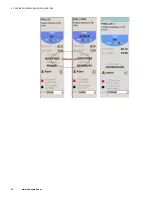
•
If the
Caution
symbol appears against any field, you must click
Adjust
to update the particular field.
2
Click
Apply
.
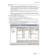
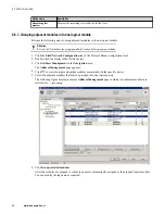
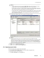
6.4.3 Configuring the field network tag names
The procedure of configuring field network tag names for Drive devices and AS-I link/AS-I Link Advanced is
slightly different from this procedure. For more information, see
Configuring field network devices tag names
for the Drive devices and
Configuring field network tag names for the AS-i Link/AS-i Link Advanced devices
respectively.
6 PROTOCOL BLOCK
72
www.honeywell.com
Summary of Contents for Experion PKS
Page 1: ...Experion PKS PROFIBUS Gateway Module User s Guide EPDOC XX88 en 431E June 2018 Release 431 ...
Page 8: ...CONTENTS 8 www honeywell com ...
Page 10: ...1 ABOUT THIS GUIDE 10 www honeywell com ...
Page 32: ...4 PROFIBUS GATEWAY MODULE PGM INSTALLATION 32 www honeywell com ...
Page 58: ...5 PROFIBUS GATEWAY MODULE PGM BLOCK 58 www honeywell com ...
Page 69: ...6 PROTOCOL BLOCK 69 ...
Page 103: ...5 Click OK 6 PROTOCOL BLOCK 103 ...
Page 110: ...6 PROTOCOL BLOCK 110 www honeywell com ...
Page 183: ...PDC Details tab Figure 6 Detail Display of PDC Details tab 7 DEVICE SUPPORT BLOCK DSB 183 ...
Page 186: ...7 DEVICE SUPPORT BLOCK DSB 186 www honeywell com ...
Page 231: ...9 PROFIBUS I O MODULE PIOMB FUNCTION BLOCK 231 ...
Page 232: ...9 PROFIBUS I O MODULE PIOMB FUNCTION BLOCK 232 www honeywell com ...
Page 236: ...10 PROFIBUS GATEWAY MODULE PGM CONFIGURATION EXAMPLE 236 www honeywell com ...
Page 264: ...13 PROFIBUS GATEWAY MODULE PGM TROUBLESHOOTING 264 www honeywell com ...


