background image

Date of Issue: April 2008

7-3

WDP30X

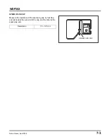
SPARK PLUG CAP

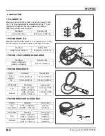
Measure the resistance of the spark plug cap by touching 
one test lead at the wire end of the cap, and the other at the 
spark plug end.

Resistance

7.5 ~ 12.5 k

SPARK PLUG CAP

Summary of Contents for WDP30X

Page 1: ...derstanding of all basic shop safety practices and that you are wearing appropriate clothing and using safety equipment When performing any service task be especially careful of the following Read all...

Page 2: ...e provided safety messages and other safety information throughout this manual Of course it is not practical or possible to warn you about all the hazards associated with servicing this pump You must...

Page 3: ...ii Revised April 2012 PSV61TDP00E2 WDP30X...

Page 4: ...tank capacity 2 0 0 53 US gal Engine oil capacity 0 56 0 59 US qt Type Diaphragm with spring type connecting rod Suction port diameter 3 in NPT Discharge port diameter 3 in NPT Maximum total head 15...

Page 5: ...min 1 rpm Ignition system Transistorized magneto ignition Ignition timing 25 B T D C fixed 20 3 B T D C 300 4 200 min 1 rpm Spark plug BPR6ES NGK Lubrication system Splash type Oil capacity 0 56 0 59...

Page 6: ...required if the vertical distance from water to the pump suction head is less than 16 feet The suction head can be increased to 24 feet if the pump is primed TOTAL HEAD 0 10 20 30 40 50 40 50 60 70 80...

Page 7: ...DP30X 3 DIMENSIONAL DRAWINGS Dimensions are with the handlebar installed over the engine 654 mm 25 7 in 800 mm 31 5 in 594 mm 23 4 in 755 mm 30 5 in 635 mm 25 0 in 826 m m 32 5 in WDP30X WDP30XK1 K2 R...

Page 8: ...Date of Issue April 2008 1 5 WDP30X 4 WIRING DIAGRAM SPARK PLUG IGNITION SWITCH OIL ALERT UNIT OIL LEVEL SWITCH BL BL Y BL BLACK Y YELLOW IGNITION CONTROL MODULE Y...

Page 9: ...1 6 Date of Issue April 2008 WDP30X...

Page 10: ...Lubricate sliding surfaces before assembly After assembly check parts installation and operation 2 SYMBOLS USED IN THIS MANUAL As you read this manual you may find the following symbols with the inst...

Page 11: ...WDP30X 3 SERIAL NUMBER LOCATIONS There are two serial numbers one for the engine and one for the frame Always refer to these numbers when ordering parts and when making technical inquiries ENGINE SERI...

Page 12: ...Oil Ring end Top Second gap Oil 1 5 mm 0 06 in 2 5 mm 0 10 in 0 015 0 045 mm 0 0006 0 0018 in 0 15 0 35 mm 0 006 0 014 in 0 15 0 35 mm 0 006 0 014 in 1 37 mm 0 054 in 2 37 mm 0 093 in 0 15 mm 0 006 i...

Page 13: ...over bolt 6 x 1 0 CT 12 1 2 9 Air cleaner wing nut 6 x 1 0 9 0 9 6 5 Muffler mounting nut 8 x 1 25 24 2 4 18 Oil drain bolt 10 x 1 25 18 1 8 13 Fuel tank flange nut 6 x 1 0 10 1 0 7 Sediment cup 24 x...

Page 14: ...ation 3 Driver 40 mm ID 07746 0030100 Driver for attachments 4 and 5 4 Attachment 25 mm ID 07746 0030200 Timing gear installation 5 Attachment 30 mm ID 07746 0030300 Governor drive gear installation 6...

Page 15: ...l removal 3 Flywheel puller OTC 1035 Flywheel removal 4 Digital multimeter FLU 88 Electrical component testing 5 Combustion chamber cleaning brush and drill extension Procured locally Clean combustion...

Page 16: ...heck spark plug operation P 2 8 WEAK OR NO SPARK See IGNITION SYSTEM TROUBLESHOOTING P 2 8 Check ignition coil air gap P 7 2 GOOD SPARK 4 Check choke adjustment or throttle adjustment P 3 8 CHOKE PART...

Page 17: ...all new spark plug P 3 5 NO SPARK 3 Disconnect the black wire from the engine stop switch and recheck SPARKS Faulty engine stop switch Replace the engine stop switch P 5 4 NO SPARK Defective ignition...

Page 18: ...LEAKS Tighten couplings OK 5 Clappet valve DAMAGED Install wear plate and gasket or replace clappet valve P 10 1 Discharge volume or pressure is too low 1 Suction head TOO GREAT Move pump closer to th...

Page 19: ...2 10 Date of Issue April 2008 WDP30X...

Page 20: ...IOD 1 Refer to page ITEM Perform at every indicated interval Before each use After each use First month or 20 hours Every 3 months or 50 hours Every 6 months or 100 hours Every year or 300 hours Engin...

Page 21: ...er or service station for reclamation Do not throw it in the trash or pour it on the ground or down a drain 4 Refill with the recommended oil to the upper limit mark on the dipstick Check oil level wi...

Page 22: ...at the oil level is at the upper limit mark on the dipstick c OIL CHANGE Change the gearbox oil while the gearbox is warm to assure complete and rapid draining Remove the two 8 x 15 mm bolts and washe...

Page 23: ...warm soapy water rinse and allow to dry thoroughly or clean with a high flash point solvent and allow to dry thoroughly Dip the element in clean engine oil and squeeze out all the excess oil Excess oi...

Page 24: ...de electrode 3 Make sure the sealing washer is in good condition and replace if necessary 4 Install the plug finger tight to seat the washer then tighten with a plug wrench New plug tighten 1 2 turn a...

Page 25: ...and remove the muffler from the cylinder head 2 Remove the 4 mm screw from the spark arrester and remove the spark arrester from the muffler 3 Use a stiff brush to remove carbon deposits from the spa...

Page 26: ...stroke and the exhaust stroke 3 Insert a feeler gauge between the rocker arm and the valve to measure valve clearance 4 If adjustment is necessary a Hold the rocker arm pivot and loosen the rocker ar...

Page 27: ...L STRAINER CUP CLEANING 1 Turn off the fuel valve and remove the fuel strainer cup and O ring 2 Wash the strainer cup in nonflammable or high flash point solvent 3 Install the O ring and sediment cup...

Page 28: ...damaged 5 Clean the fuel tank with nonflammable or high flashpoint solvent and allow to dry thoroughly 6 Check to be sure the O ring is in place and install the strainer and fuel valve Tighten the fue...

Page 29: ...ly and bring the engine to its standard speed with the throttle lever Adjust the throttle control screw so that the throttle cannot be moved past this point 12 PUMP CLAPPET VALVE INSPECTION Inspect th...

Page 30: ...Date of Issue April 2008 4 1 WDP30X 4 AIR CLEANER CARBURETOR 1 AIR CLEANER REMOVAL INSTALLATION 1 AIR CLEANER 4 1 2 CARBURETOR 4 3 P 3 4 P 3 4...

Page 31: ...l the air cleaner cover with the long skirt portion facing toward the front WING NUT GROMMET BREATHER TUBE COLLAR BOLT 6 x 20 mm INNER FILTER PAPER OUTER FILTER FOAM AIR CLEANER ELBOW SEAL AIR CLEANER...

Page 32: ...Date of Issue April 2008 4 3 WDP30X 2 CARBURETOR a REMOVAL INSTALLATION ASSEMBLY INSULATOR GASKET SPARK PLUG WIRE CARBURETOR GASKET THROTTLE RETURN SPRING GOVERNOR ROD FUEL TUBE...

Page 33: ...4 4 Date of Issue April 2008 WDP30X b DISASSEMBLY ASSEMBLY CLEANING P 4 5 REPLACEMENT P 4 5 CLEANING P 3 8 60 REPLACEMENT P 4 4 ASSEMBLY ASSEMBLY ASSEMBLY ASSEMBLY ASSEMBLY P 3 8 P 4 5 P 4 4 P 4 5...

Page 34: ...led NOTICE Tampering is a violation of Federal and California law 1 When the limiter cap has been broken off remove the broken pilot screw 2 Place the spring on the replacement pilot screw and install...

Page 35: ...a carburetors High air pressure may damage the carburetor Use low air pressure 30 psi or less when cleaning passages and ports 1 Clean the carburetor body with high flash point solvent 2 Use low air p...

Page 36: ...During assembly take care not to allow the return spring to come out RECOIL STARTER ASSEMBLY INSTALLATION Remove dirt and debris before installation ASSEMBLY P 5 2 6 x 10 3 6 x 12 4 FAN COVER P 5 2 RA...

Page 37: ...case Align the spring inner hook to the case claw on the case by turning the reel counterclockwise 5 Apply grease to the friction spring and inside of the ratchet cover 6 Install the ratchet spring an...

Page 38: ...l turns counterclockwise to preload the return spring 9 Pass the rope through the starter case hole and starter grip and knot the end of the rope as shown 10 Check the operation of the ratchet by pull...

Page 39: ...5 4 Date of Issue April 2008 WDP30X 2 FAN COVER REMOVAL INSTALLATION From oil level switch YELLOW YELLOW From ignition coil OIL ALERT UNIT ENGINE SWITCH BLACK Retaining clip...

Page 40: ...th the long end side toward the control base FUEL TANK CAP ASSEMBLY Make sure that the air vent hole is clean and unclogged Blow with compressed air if necessary GOVERNOR SPRING ASSEMBLY Install with...

Page 41: ...fuel filler neck by aligning the projections 5 of the cap with the cutouts of the fuel filler neck and fuel level gauge and then turn the fuel tank cap clockwise 180 degrees to lock it FUEL TANK JOIN...

Page 42: ...for a while after operation Be sure that the engine is cold before muffler removal installation MUFFLER ASSEMBLY Install the muffler after removing the carbon deposits with a plastic hammer UPPER MUFF...

Page 43: ...6 2 Date of Issue April 2008 WDP30X...

Page 44: ...ribs on the crankcase as shown FLYWHEEL DISASSEMBLY Remove the ignition coil before removing the flywheel Do not hit the flywheel with a hammer Remove with a commercially available 6 inch puller Avoid...

Page 45: ...CTION IGNITION COIL Primary side Measure the resistance of the primary coil by attaching one ohmmeter lead to the ignition coil s primary black lead while touching the other lead to the iron core Seco...

Page 46: ...ue April 2008 7 3 WDP30X SPARK PLUG CAP Measure the resistance of the spark plug cap by touching one test lead at the wire end of the cap and the other at the spark plug end Resistance 7 5 12 5 k SPAR...

Page 47: ...7 4 Date of Issue April 2008 WDP30X...

Page 48: ...HEAD COVER 6 x 12 2 SHROUD DOWEL PIN 2 CYLINDER HEAD REMOVAL INSTALLATION Before installation remove any carbon deposits from the com bustion chamber and inspect the valve seats Measure the cylinder c...

Page 49: ...e the rod ends are firmly seated in the lifters VALVE SPRING 2 INSPECTION P 8 3 CYLINDER HEAD INSPECTION P 8 3 INTAKE VALVE ASSEMBLY Do not interchange with the exhaust valve INSPECTION P 8 4 VALVE HE...

Page 50: ...or over the service limit recondition the valve seat P 8 6 CYLINDER HEAD Remove carbon deposits from the combustion chamber Clear any gasket material from the cylinder head surface Check the spark plu...

Page 51: ...ain the guide to stem clearance If the guide to stem clearance exceeds the service limit determine if the new guide with standard dimensions would bring the clearance within tolerance If so replace an...

Page 52: ...OTICE When driving the valve guides out be careful not to damage the head 4 Remove the new valve guides from the refrigerator one at a time as needed 5 Install the new valve guides from the valve spri...

Page 53: ...ion chamber and valve seats to remove carbon deposits Apply a light coat of Prussian Blue or erasable felt tipped marker ink to the valve face 2 Insert the valve and snap it closed against its seat se...

Page 54: ...t its seat several times Be sure the valve does not rotate on the seat The seating surface as shown by the transferred marking compound should have good contact all the way around 7 Lap the valves int...

Page 55: ...8 8 Date of Issue April 2008 WDP30X...

Page 56: ...FT ASSEMBLY Before installing inspect for worn and weakened springs and check that the decompressor weight moves smoothly INSPECTION P 9 7 VALVE LIFTER 2 DISASSEMBLY When removing mark so that the IN...

Page 57: ...part of the governor drive gear and remove the crankshaft and timing gear using a hydraulic press Remove the governor drive gear in the same way ASSEMBLY TIMING GEAR Using the old gear for reference...

Page 58: ...ATED SECOND RING OIL RING COMBINATION RING 120 120 10 mm 0 4 in 10 mm 0 4 in SIDE RAIL 2 SPACER OIL RING SECOND RING TOP RING MARKING 120 CONNECTING ROD ASSEMBLY Install the connecting rod with the lo...

Page 59: ...mm 2 36 in 60 165 mm 2 3687 in Standard Service limit 59 985 mm 2 3616 in 59 845 mm 2 3561 in Standard Service limit 0 015 0 050 mm 0 0006 0 0020 in 0 12 mm 0 005 in K1QX2 Standard Service limit Top...

Page 60: ...15 0 35 mm 0 008 0 014 in 1 0 mm 0 04 in UT1 2 QX2 Standard Service limit Top 0 20 0 35 mm 0 008 0 014 in 1 0 mm 0 04 in Second 0 35 0 50 mm 0 014 0 020 in 1 0 mm 0 04 in Oil 0 20 0 70 mm 0 008 0 028...

Page 61: ...nnecting rod and cap and tighten the connecting rod bolts to the specified torque TORQUE 12 m 1 2 kg m 9 ft lb Do not rotate the crankshaft while the plastigauge is in place Original size Standard Ser...

Page 62: ...rance CAMSHAFT CAM HEIGHT CAMSHAFT O D CAMSHAFT HOLDER I D Standard Service limit 0 040 0 063 mm 0 0016 0 0025 in 0 12 mm 0 005 in Standard Service limit IN 27 70 mm 1 090 in 27 45 mm 1 081 in EX 27 7...

Page 63: ...ar Be sure to install the governor weight before installing the crankshaft 6 mm PLAIN WASHER GOVERNOR WEIGHT PIN 2 6 mm THRUST WASHER GOVERNOR ARM SHAFT LOCK PIN ASSEMBLY Install the lock pin immediat...

Page 64: ...T WASHER 4 CONNECTING ROD ASSEMBLY P 10 2 3 in SUCTION PORT AIR CHAMBER PLUG O RING AIR CHAMBER PLUG LOWER CASE DIAPHRAGM INSPECTION P 10 3 INSTALLATION P 10 3 CONNECTING ROD FLANGE NYLON WASHER 2 BUS...

Page 65: ...Place the upper rod end in a vise using slight pressure 2 Apply Hondalock to the threads of the bolt and pass the bolt through the lower rod end inner ring and spring 3 Tighten the bolt to compress t...

Page 66: ...ft 2 Pull the starter grip slowly until the diaphragm pulls up against the upper case stops 3 Install the upper case assembly making sure the diaphragm is centered and not pinched between the case sto...

Page 67: ...10 4 Date of Issue April 2008 WDP30X...
Page 68: ...ET S N WZCA 6000825 later BEARING To CASE DIAPHRAGM P 10 1 S N WZCA 6000001 6000824 CAP DIPSTICK PLUG Continued on next page S N WZCA 6000001 6000824 WASHER SHAFT GEAR GEAR KEY KEY 3 SHAFT WASHER BEAR...

Page 69: ...S 6 x 1 x 25 mm ALLEN SCREW 10 LIFTING BAIL COVER PIN GASKET BEARING CLIP ENGINE MOUNTING BRACKET ENGINE ADAPTER 5 16 x 18 x 1 5 HEX BOLT 4 5 16 in WASHER 8 5 16 in LOCKNUT 4 10 x 1 5 STUD 4 15 N m 11...

Page 70: ...PLUG WASHER GASKET BEARING To CASE DIAPHRAGM P 10 1 CAP DIPSTICK Continued on next page WASHER SHAFT GEAR HELICAL GEAR HELICAL KEY KEY 3 SHAFT BEARING GEARBOX CASE SEAL WDP30XK1 K2 S N WZCA 6200001 la...

Page 71: ...mm ALLEN SCREW 10 LIFTING BAIL COVER PIN GASKET BEARING CLIP ENGINE MOUNTING BRACKET ENGINE ADAPTER 5 16 x 18 x 1 5 HEX BOLT 4 5 16 in WASHER 8 5 16 in LOCKNUT 4 15 N m 11 ft lb From previous page SCR...

Page 72: ...1 WDP30X 12 FRAME WHEELS 1 FRAME WHEELS DISASSEMBLY ASSEMBLY 1 FRAME WHEELS 12 1 12 mm NUT 4 12 mm STAR WASHER 4 12 mm FLAT WASHER 4 FRAME SPRING 2 FRAME ASSEMBLY WDP30X S N WZCA 6000001 6099999 To C...

Page 73: ...WASHER 4 12 mm FLAT WASHER 4 HANDLE QUICK RELEASE RING PIN 3 8 x 1 3 4 in BOLT 2 3 8 in WASHER 4 3 8 16 LOCKNUT 2 20 N m 27 ft lb 5 16 18 x 1 5 in HEX BOLT 4 5 16 18 NYLOCK NUT 4 15 N m 11 ft lb AXLE...

Page 74: ...arbox Assembly 11 1 Grease 3 3 Governor Adjustment 3 10 Disassembly Assembly 9 8 Idle Speed Adjustment 3 8 Ignition Coil Air Gap Adjustment 7 2 Disassembly Assembly 7 1 Inspection 7 2 Maintenance Sche...

Page 75: ...Date of Issue April 2008 13 2 WDP30X...

Reviews: