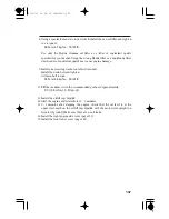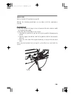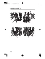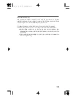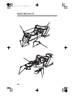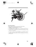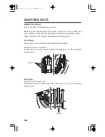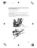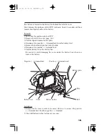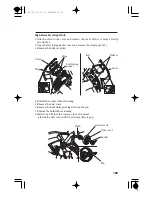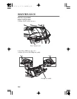
Position the wheel between the fork legs and insert the front axle shaft
from the left side, through the left fork leg and wheel hub.
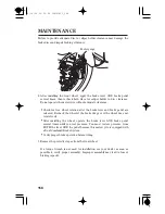
Reassemble the removed parts in the reverse order of removal.
Fit the brake disc carefully between the brake pads to avoid damaging the
pads.
If the feeler gauge cannot be inserted easily, loosen the left axle pinch bolt
and pull the left fork outward or push inward to adjust the clearance. Then
tighten the axle pinch bolts to the specified torque.
If the feeler gauge inserts easily, remove it and tighten the axle pinch
bolts to the specified torque:
Measure the clearance between the brake disc and the caliper holder on
each side with a 0.7 mm (0.028 in) feeler gauge.
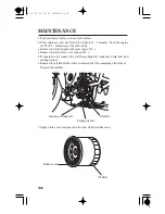
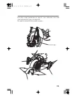
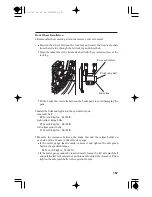
Align the index line of the front axle shaft with the recessed surface of the
fork leg.
Install the bolts and tighten to the specified torque:
front axle bolt:
right caliper fixing bolts:
left caliper socket bolts:
1.
2.
3.
Index line
Recessed surface
Front axle shaft
Front Wheel Installation
157
59 N·m (6.0 kgf·m , 44 lbf·ft)
31 N·m (3.2 kgf·m , 23 lbf·ft)
31 N·m (3.2 kgf·m , 23 lbf·ft)
22 N·m (2.2 kgf·m , 16 lbf·ft)
12/12/06 16:29:45 32MJG600_167
Summary of Contents for Goldwing F6B
Page 25: ...15 TYRE INFORMATION LABEL CARGO LIMIT LABEL CARGO LIMIT LABEL 12 12 06 16 14 21 32MJG600_025 ...
Page 28: ...For KO type For SI type MOTORCYCLE SAFETY 18 12 12 06 16 14 40 32MJG600_028 ...
Page 31: ...Saddlebag Radio antenna Rear brake pedal 21 12 12 06 16 14 52 32MJG600_031 ...
Page 166: ...MAINTENANCE 156 12 12 06 16 29 36 32MJG600_166 ...
Page 170: ...MAINTENANCE 160 12 12 06 16 30 02 32MJG600_170 ...

