background image


11 


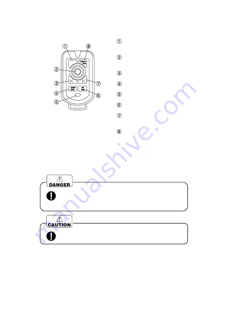
HANDLING OF REMOTE (OPTION) 


When


you operate it, face the top of remote to infrared ray sensor of main unit and 

press the key.   


・  

2 pcs. sum-3 (AA) batteries are required for operation in case of wireless remote. 


  MODE

(→

page 18

) 

It switches Fish Finder mode and Plotter 
mode (for HE-7301

).


  CENTER key 

Move map and cursor.


It is also used to select menu item.


  DETAILED (EXPANSION)

(→

page 26

) 

Enlarge displayed map (detail)


  EVENT MARK

(→

page 32

) 

Enter event mark on the display


  WAKE ON/OFF

(→

page 38

) 

Switch display or non display of wake


WP SAVE

(→

page 41

) 

Store waypoint.


WIDE AREA(REDUCTION)

(→

page 

26

) 

Reduce the display (Wide area).


  CURSOR ON/OFF

(→

page 24

) 

Switch display/non display of cursor.


<

Simple Remote

Option

) 

Control  keys  which  are  usually 
used are concentrated. 


Do not use leaked battery.(When using wireless remote) 

    When leaked liquid stains on body, it may cause to damage. 

In case of staining, wash out with clean water immediately.


Keep at the place where it will not drop due to vibration, etc. when


it is not used. It causes to accident like human damage. 

Summary of Contents for HE-1501

Page 1: ...HE 7301 GPS COLOR LCD PLOTTER SOUNDER HE 1501 HE 7302 HE 1502 GPS COLOR LCD PLOTTER...

Page 2: ...re you will not lose or break so as to read soon when it is necessary In case that you resell or transfer this unit please give it to the new owner We will not be responsible for product liability PL...

Page 3: ...FRONT PANEL 7 2 REAR SIDE 9 3 REMOTE 10 HOW TO SEE THE DISPLAY 13 HOW TO OPERATE MENU 14 BASIC OPERATION POWER ON OFF 16 TO CHANGE THE DISPLAY 17 TO CONTROL BRIGHTNESS OF SCREEN 19 TO SHOW SIMULATION...

Page 4: ...51 TO INDICATE PLACE NAME TIDE CURRENT AND ETC 51 TO SHOW LATITUDE LONGITUDE LINE GRID 52 TO SOUND ARRIVAL ANCHOR WATCH OFF COURSE ALARM 52 OWN BOAT S VECTOR AND COLOR OF OWN BOAT S MARK 53 TO SET RE...

Page 5: ...89 TO SET SWEEPING SPEED 89 TO SET AUTO RANGE Automatic Range Control 90 TO SET AUTO SHIFT Automatic Display Range Shift 90 TO SET AUTO GAIN Automatic Sensitivity Control 90 TO SET A MODE 91 TO SET B...

Page 6: ...ION OF MAIN UNIT 102 INSTALLATION OF MAIN UNIT ONTO DASHBOARD 104 INSTALLATION OF TRANSDUCER 108 THRU HULL INSTALLATION 108 INSTALLATION OF WATER TEMP SENSOR 109 STANDARD COMPOSITION 110 OPTION PARTS...

Page 7: ...the information displayed on the screen of unit for navigation directly It causes to the marine disaster Please be sure to use the official marine charts for navigation judgment Do not operate the uni...

Page 8: ...mble or modify the cables It causes to heating firing or electric shock Do not use the damaged cables It causes to firing or electric shock Do not pull the cable when you pull out the plug It causes t...

Page 9: ...ugh the hull If water proof is not sufficient it causes to marine disaster because water comes in Do not install on the aluminum boat It may cause to corrosion When you work using electric tools pleas...

Page 10: ...unstable and risky Installation and maintenance of GPS antenna should be done after you land and fix the boat Unless you keep it human damage resulting in death or serious wound will occur GPS antenna...

Page 11: ...n voltage of battery varies heavily It may influence to the unit Make sure to put the power switch off when you start to run the engine Be sure to put the power switch off when you start to run the en...

Page 12: ...f you remove cable Only when wireless remote is used it operates with internal battery It helps to save power consumption Many information You can save up to 1 000 points of waypoints up to 24 000 poi...

Page 13: ...layed map detail ZOOM page 77 78 Move expanded area toward sea surface or sea bottom When manual EXP is selected Enter specified event mark page 60 Infrared ray sensor POWER KNOB Power ON OFF page 16...

Page 14: ...F page 24 Switch display non display of cursor RANGE SWITCH page 27 Alternately switch range set on menu WAKE ON OFF page 38 Switch display or non display of wake WAKE COLOR page 38 Select color of di...

Page 15: ...y for monitor 5P Option RGB Video Signal Output Option External Input Output 6P Remote 4P To GPS DGPS Antenna 6P Water Temperature Sensor 8P Optional DC Power Supply 2P Transducer 3P For HE 7301 5 Pin...

Page 16: ...q mode Enter specified event mark page 60 SHIFT for HE 7301 page 76 Move displayed depth range Enter specified event mark Page 60 ZOOM page 77 78 Move expanded area toward sea surface or sea bottom Wh...

Page 17: ...page 32 Enter event mark on the display WAKE ON OFF page 38 Switch display or non display of wake WP SAVE page 41 Store waypoint WIDE AREA REDUCTION page 26 Reduce the display Wide area CURSOR ON OFF...

Page 18: ...nt kinds of batteries together Battery can not be charged When remote is not used for a long time take out the batteries When the solution is leaked from battery wipe off the stained solution from cas...

Page 19: ...isplay is HE 7301 On the HE 7302 fish finder display on right side of screen is not shown 600W 200kHz 1 2kW 200kHz 3 0kW 200kHz 600W 50kHz 1 2kW 50kHz or 3 0kW 50kHz does not have dual frequency funct...

Page 20: ...CENTER key Show next menu with Right of CENTER key and select desired item Press MENU key to return previous display Until set items are shown repeat procedure 2 and procedure 3 to the extent of nece...

Page 21: ...15 BASIC OPERATION POWER ON OFF 16 HOW TO CHANGE THE DISPLAY 17 TO CONTROL BRIGHTNESS OF SCREEN 19 TO SHOW SIMULATION DISPLAY 19...

Page 22: ...ON for the first time after installed it takes about 5 30 minutes to show the correct position in order to collect the satellite datum Note 2 When the engine starts to run battery voltage varies and m...

Page 23: ...ssing MODE key for a long time change division size with of CENTER key 1 Change the display MODE key In case of HE 7302 Each time when you press MODE key you can change from NORMAL display to GPS Rece...

Page 24: ...is shown you can change the display division proportion by pressing S key and PL key for a long time It is effective for only standard supplied remote and can not be done with simple remote MEMO You...

Page 25: ...nect with GPS or transducer you can practice the operation etc Select 8 OTHERS 8 INITIAL 5 SIMULA TION on menu Select item with CENTER key and press SET key OFF Simulation display OFF FIX Own boat is...

Page 26: ...44 TO DRAW LINE 45 TO ERASE LINE 46 TO REGISTER ERASE ROUTE 48 TO RECALL REGISTERED ROUTE SETTING ROUTE NAVIGATION 49 TO ADVANCE WAYPOINT TO RETURN WAYPOINT 50 TO SHOW DEPTH LINE 51 TO INDICATE PLACE...

Page 27: ...is not indicated cursor line distance direction and required time from own boat s position to cursor is not shown 1 ON OFF of Cursor CURSOR ON OFF key Indicate the cursor by pressing CURSOR ON OFF ke...

Page 28: ...en in case that 6 READOUT SETTING 1 MAP READOUT 7 MAP SCROLL 1 CETERING is ON However in case of moving the display manually this function does not activate After you indicate own boat to center of sc...

Page 29: ...range and scale are same as wake s In case of single map display Display expands by pressing EXP key Display reduces by pressing RED key In case of dual map display Display expands by pressing EXP key...

Page 30: ...m just upper of screen Auto Course Up OFF Only when COURSE UP key is pressed just upper of screen is shown as Bearing of own boat 1 Selection of direction TO SET RANGE YOU ALWAYS USE If you preset oft...

Page 31: ...of main unit Insert the map card into card connector while sticker side faces ahead Please make sure to face sticker side of map card memory card ahead Unless you keep it internal connector may be bro...

Page 32: ...ver 1 2 3 Note 1 When you insert take off memory card make sure to the power of unit OFF Note 2 Storage of datum in this unit or memory card is not guaranteed to keep permanently Important datum shoul...

Page 33: ...a is stored in that block Select item which you store with key and press SET key Red letter item indicates that item s data is stored in card If data is not stored in card copy is completed When data...

Page 34: ...block number indicates some data is stored in that block Select item which you store with key and press SET key Red letter item indicates that item s data is stored in card If data is not stored in un...

Page 35: ...he position of fish school shoals or etc at any option Shape 8 types selected on menu Color Selected among red yellow green magenta white cyan blue and color of wake Numbers of point Up to 24 000 poin...

Page 36: ...is entered at cursor s position In case of HE 7301 8 OTHERS 8 INITIAL 7 SPECIAL MENU 8 F F KEY AT PL on menu should be set to USED FOR PL KEY When it is delivered from factory it is set to USED FOR PL...

Page 37: ...by color are erased by pressing SET key 1 To erase by color 2 3 All event marks which are selected by each shape are erased Select 3 EVENT MARK 1 ERASE 2 ERASE BY SHAPE on menu Select and designate s...

Page 38: ...play to confirm Event mark is erased by pressing SET key Event mark is canceled by pressing CLR key 1 To erase by cursor 2 3 Note 1 When unit is delivered from factory 3 EVENT MARK 1 ERASE 1 ERASE BY...

Page 39: ...cate first 10 items LAST Indicate last 10 items 1 To edit event mark 2 You can edit shape color latitude and longitude at every event mark manually You can also enter comment name 1 2 2 ENTER EDIT Sel...

Page 40: ...is in comment column and comment is written on it NUMBER key Enter cursor position with number RANGE CHANGE key Mark color can be changed by pressing key at MARK SHAPE position If you store after cha...

Page 41: ...cord by selecting WAKE COLOR on menu page 39 Wake color changes each time when you press WAKE COLOR key Selectable from 7 colors Red Yellow Green Magenta White Cyan Blue 1 Show Record of wake 2 3 Memo...

Page 42: ...en you said for a long time distance it is recommended to set the memory interval to long TO ERASE WAKE All wakes which are selected by each color are erased Select 1 WAKE 4 WAKE ERASE 1 ERASE BY COLO...

Page 43: ...ke by cursor 2 3 Note 1 When unit is delivered from factory 1 WAKE 4 ERASING WAKES 3 ERASE BY CURSOR is set to OFF page 63 Set ERASE BY CURSOR to ON to execute this function By pressing CLR key displa...

Page 44: ...morized shown waypoint mark and waypoint number 0 999 is shown Number is renewed each time when waypoint is memorized newly However in case there are waypoints which were erased before number will be...

Page 45: ...y color are erased by pressing SET key 1 To erase waypoint by color 2 3 All waypoint marks which are selected by each shape are erased Select 2 WAYPOINT 3 ERASE WAYPOINT 2 ERASE BY SHAPE on menu Selec...

Page 46: ...display to confirm Waypoint mark is erased by pressing SET key Erasing is canceled by pressing CLR key 1 To erase waypoint marks by cursor 2 3 Note 1 When unit is delivered from factory 2 WAYPOINT 3...

Page 47: ...pagesbefore TOP Indicate first 10 items LAST Indicate last 10 items 1 To edit waypoint mark 2 You can edit shape color latitude and longitude at every waypoint mark manually 1 2 2 ENTER EDIT Select 3...

Page 48: ...omment column and comment is written on it NUMBER key Enter cursor position with number RANGE CHANGE key Mark color can be changed by pressing key at MARK SHAPE position If you store after changing wa...

Page 49: ...the upper left of screen Press WP RECALL key Enter number of waypoint with NUMBER key It is also done by stacking cursor on waypoint mark instead of By pressing SET key waypoint navigation is set 1 S...

Page 50: ...ed Move cursor to point to be waypoint with key By pressing WP SAVE key for a long time simple waypoint is set Simple waypoint is temporary waypoint Data is not left in unit When map are shown on dual...

Page 51: ...awing line When you finish to draw line press CLR key 1 Drawing Line 2 3 4 5 In case of remote By pressing CURSOR ON OFF key cursor is shown Move the cursor to the position which you will start to dra...

Page 52: ...left of screen Color can be changed only when line is being drawn Color can not be changed after line was drawn SET key TO ERASE LINE All lines which are selected by each color are erased Select 8 OT...

Page 53: ...E BY CURSOR on menu beforehand in order to achieve this function page 67 Select 8 OTHERS 1 DRAW LINE 4 ERASE LINE 3 ERASE BY CURSOR Set 3 ERASE BY CURSOR to ON page 69 By pressing CURSOR ON OFF key cu...

Page 54: ...ach intermediate point and they are connected in line Route registration is completed by pressing CLR key To erase route Select 4 ROUTE 3 ERASE ROUTE on menu page 64 1 To register erase route Route Li...

Page 55: ...iate point for this case is registered as starting point At the same time own boat is connected with next intermediate point course change point as waypoint line 2 If it is judged that own boat passes...

Page 56: ...oute in turn Waypoint Line Line connected between own boat and intermediate point page 52 Set Route Navigation page 51 Select 4 ROUTE 5 ADVANCE WAYPOINT on menu Each time when you press SET key waypoi...

Page 57: ...line is line that same deep bottoms are connected You can show or erase the depth line TO INDICATE PLACE NAME TIDE CURRENT AND ETC Select 6 READOUT SETTING 1 C MAP SETTING 6 OTHER OBJECT on menu Set e...

Page 58: ...waypoint or route point alarm sounds To sound alarm Select 6 READOUT SETTING 1 C MAP SETTING 2 LAT LON GRID on menu Set displayed color with of CENTER key When OFF is selected latitude longitude line...

Page 59: ...displayed when waypoint navigation or route navigation is set within a circle with specified distance from a waypoint or route point and arrival or anchor alarm is set at the same time Course line Cou...

Page 60: ...acy of each information 2 TO CHANGE SIZE COLOR AND ETC OF CHARACTERS You can change attribute size and color of informational characters information like latitude longitude etc Example Change the attr...

Page 61: ...of Loran C Loran C Loran C Long Range Navigation is hyperbolic navigation system using long wave band Theory of locus of point that difference of arrival time of signal transmitted from two stations...

Page 62: ...FREQ of 2 BEACON SETTING is set to AUTO both frequency and baurate are set automatically In case of MANUAL setting of frequency and baurate are needed 1 To set DGPS beacon receiver for only DGPS model...

Page 63: ...ERS 8 INITIAL 7 SPECIAL MENU 5 F F KEY AT PL on menu Select item INVALID This function is invalid USED Fish finder key is allocated to plotter key When display is plotter mode it is effective 1 To all...

Page 64: ...navigation is set recall and designate waypoint by entering WAYPOINT waypoint number 2 CANCEL Cancel waypoint navigation WAYPOINT Same function as WP RECALL key CLR key page 47 3 ERASE 1 ERASE BY COLO...

Page 65: ...on is set recall and designate route ROUTE by entering route number 2 CANCEL ROUTE Cancel route navigation 3 ERASE 1 ALL Erase all registered routes ROUTE 2 ERASE BY NUMBER Designate route number and...

Page 66: ...LAVE STATION1 Set slave station of Loran C page 58 Y 25 3 SLAVE STATION2 Set slave station of Loran C page 58 Z 38 4 SLA STA 1 CORRET Set slave corrected value for slave station of Loran C page 58 0 0...

Page 67: ...longitude boat speed bearing and measured time L M S Designate size of character ALL M OFF Not indicate COLOR Indicate in designated color ALL YELLOW 7 WAYPOINT Designate size color indicate or not in...

Page 68: ...of CENTER key 9 00 2 GPS AZIMUTH 1 GPS AZIMUTH Select GPS Azimuth Real Azimuth Magnetic Azimuth 2 MAG AZIMUTH Set magnetic azimuth It is effective when upper DEVIATION item is set to Magnetic Azimuth...

Page 69: ...HE 1501 INVALID USE 6 CONTRAST SET Adjust contrast of fish finder display Adjust to visible 1 7 SPECIAL 1 USER KEY Allocate USER key for some settings MENU 2 11 LC CMAP ON OFF SPOT S COLOR TONE 2 COLO...

Page 70: ...or not 69 9 Set if SEABED TYPE is shown or not 70 10 Set if WRECKS Obstruction is shown or not 70 11 Set if PORT and PORT SERVICES are shown or not 70 12 Set Navigational Aids 71 13 Set if MIXING LEV...

Page 71: ...or not 69 9 Set if SEABED TYPE is shown or not 70 10 Set if WRECKS Obstruction is shown or not 70 11 Set if PORT and PORT SERVICES are shown or not 70 12 Set Navigational Aids 71 13 Set if MIXING LEV...

Page 72: ...are not to be used a replacement for official paper chart INFORMATIONS SHOWN ON THE SCREEN OF THIS UNIT SHOULD NOT BE RELIED ON FOR NAVIGATION JUDEGMENT OFFICIAL MARINE CHARTS SHOULD BE USED FOR JUDGE...

Page 73: ...66 1 ADDITIONAL C CARDS Up to two C CARDs can be inserted Card slot cover Loosen screw Take off card slot cover Insert the card...

Page 74: ...ding to user s demand Menu related to MAP SETTING is set within 6 READOUT SETTING 1 C MAP SETTING Select menu item with 6 READOUT SETTING 1 C MAP SETTING 1 DEPTH SETTING 2 SOUNDINGS LINES and then sel...

Page 75: ...4 ON OFF The default setting is ON Select menu item with 6 READOUT SETTING 1 C MAP SETTING 4 ATTENTION AREA and then select ON or OFF turning the lever left or right Set if Attention Areas is shown or...

Page 76: ...enu item with 6 READOUT SETTING 1 C MAP SETTING 6 OTHER OBJECTS 1 NAME and then select ON or OFF turning the lever left or right Set if NAME is shown or not 7 ON OFF The default setting is ON Select m...

Page 77: ...G 6 OTHER OBJECTS 4 WRECKS OBSTN and then select ON or OFF turning the lever left or right ON OFF The default setting is ON Select menu item with 6 READOUT SETTING 1 C MAP SETTING 6 OTHER OBJECTS 5 PO...

Page 78: ...jects are shown US SMP Shows Complex Object with one icon only Non complex Navigational Aids are shown using NOAA symbology INT Draws Navigational Aids using international symbology All components of...

Page 79: ...MAP SETTING 7 OTHER SETTING 4 CHART BOUNDARIES and then select ON or OFF turning the lever left or right Set if CHART BOUNDARIES is ON OFF 15 ON OFF The default setting is ON Set if DECLUTTER is ON OF...

Page 80: ...efault setting is NEG Set if AUTO COURSE Up is ON OFF 16 Set if CENTERING function is ON OFF 17 When AUTO COURSE Up is set to ON if boat turned off more than 15 from just top of screen with couse up k...

Page 81: ...LIGHT WRECKS ROCKS BUOYS BEACONS Obstructions Land Marks etc their AUTO INFO is indicated on the screen ON ALL AUTO INFO of line or area besides ON POINT is indicated OFF AUTO INFO is not indicated I...

Page 82: ...ursor with pressing key Info Tree is indicated on the upper of page and detailed information is indicated on the lower of page You can select cursor on Info Tree turning up down key up downward Detail...

Page 83: ...ions List is indicated with 7 FIND 1 PORT Finding Port 1 List of ports maximum 8 ports near to own boat near to cursor when cursor is shown is indicated When list is indicated port is selected with tu...

Page 84: ...u select port with up down key and press key while list is indicated map is redrawn so that selected port is shown at the center of screen List is indicated with 7 FIND 3 TIDE STATION Finding tide Sta...

Page 85: ...t is indicated map is redrawn so that selected Wrecks is shown at the center of screen List is indicated with 7 FIND 5 OBSTRUCTION Finding Obstructions 5 List of Obstructions maximum 8 obstructions ne...

Page 86: ......

Page 87: ...TEMP 88 TO SHOW DUAL FREQUENCY DISPLAY 89 TO SET SWEEPING SPEED 89 TO SET AUTO RANGE Automatic Range Control 90 TO SET AUTO SHIFT Automatic Display Range Shift 90 TO SET AUTO GAIN Automatic Sensitivit...

Page 88: ...Refer to TO SHOW DUAL FREQUENCY MODE page 81 600W 200kHz 1 2kW 200kHz or 3 0kW 200kHz does not have dual frequency function Water Temp Indication Water temp sensor option is indicated when optional w...

Page 89: ...eases 1 Depth Display Range Depth Display Range This sets the depth display range how deep from the surface of water is displayed Depth range you can set differs depends on frequency Depth key In case...

Page 90: ...distinguish the bottom or fish school easily 32 steps of sensitivity from 0 to 31 is displayed in bar Optimum sensitivity is that second reflection from bottom is barely displayed Second reflection Fi...

Page 91: ...200kHz or 3 0kW 200kHz does not have dual frequency function In case of remote Adjust sensitivity on left side of screen with GAIN2 key To decrease sensitivity Each time when you press GAIN2 L key gai...

Page 92: ...ant to see is small it is enlarged by setting the depth display range to shallow range when shift is selected To shift to shallow depth Each time when you press key the display range becomes shallow T...

Page 93: ...isplay You can not operate ZOOM key except for manual expansion mode Expansion rate is selected among 2 times 4 times and 8 times Expansion rate page 78 When the unit is delivered from factory it is s...

Page 94: ...isplay up or down in center of bottom MANUAL EXPANSION Expanded display up or down in the center of optional position You can move expanded area with ZOOM key as you wish Displayed range varies depend...

Page 95: ...ALARM 3 TEMP ALARM 2 TEMP SET 1 3 TEMP SET 2 1 Water Temp Alarm 2 Water Temp Alarm Alarm goes off within or out of two water temperatures TEMP SET 1 TEMP SET 2 Optional water temp sensor is required f...

Page 96: ...it is out of two depths and depth readout flashes OFF Depth alarm is canceled Select DEPTH SET 1 or DEPTH SET 2 1 Depth Alarm 2 Depth Alarm Alarm goes off within or out of two depths DEPTH SET 1 DEPTH...

Page 97: ...play 2 Following dual frequency display can be selected 600W 200kHz 1 2kW 200kHz or 3 0kW 200kHz does not have dual frequency function TO SET SWEEPING SPEED Select 9 SOUNDER 2 SWEEP SPEED on menu Esta...

Page 98: ...enu Set 3 AUTO RANGE to SHIFT 1 Auto Shift 2 Displayed range is automatically changed shifted so that sea bottom is always shown on the optimum position of screen lower half area TO SET AUTO GAIN Auto...

Page 99: ...nd it s width changes according to strength of reflected signal Strong response is indicated thick and weak signal is indicated thin TO SET BACKGROUND COLOR Select 9 SOUNDER 7 COLOR SET 1 BACK COLOR o...

Page 100: ...h finder is displayed in color by this color configuration you can know the strength of response by displayed color As display of response varies by changing color configuration it enables to display...

Page 101: ...TO SET SCALE LINE Select 9 SOUNDER 8 OTHERS 2 SCALE LINE on menu Set 2 SCALE LINE ON Indicated OFF Not indicated 1 Scale Line 2 Horizontal lines are shown at the position of depth scale on the screen...

Page 102: ...UNDER 8 OTHERS 6 SPECIAL SETUP 1 AUTO RANGE MAX on menu Set 1 AUTO RANGE MAX 30m 50m 100m 200m 300m Max Depth 1 Auto Range Max Depth 2 It sets Maximum Depth when Auto Range is operated TO SET CLEAN EC...

Page 103: ...al from plankton and air bubble When STC is set to ON sensitivity near sea surface decreases When you increases sensitivity for shallow water set STC to OFF TO SET TRANSMITTING OUTPUT Select 9 SOUNDER...

Page 104: ...n in the center of option bottom OFF Cancel expansion mode 2 EXP RATE Set expansion rate when expansion mode is set x2 2 times x4 4 times x8 8times 6 A MODE Indicate the strength of reflected signal O...

Page 105: ...97...

Page 106: ...SUPPLIED IS CONNECTED 101 INSTALLATION OF MAIN UNIT 102 INSTALLATION OF MAIN UNIT ONTO DASHBOARD 104 INSTALLATION OF TRANSDUCDER 108 1 THRU HULL INSTALLATION 108 INSTALLATION OF WATER TEMP SENSOR 109...

Page 107: ...98 HE 7301II HE 7302II Drawing of holes for installing the bracket DIMENSIONAL DRAWING...

Page 108: ...99 HE 1501 HE 1502...

Page 109: ...100 WIRING DIAGRAM...

Page 110: ...s connected with the unit you should conform geodesic system of GPS receiver with unit s Select 8 OTHERS 8 INITIAL 7 SPECIAL MENU 2 GPS GEODESIC SYSTEM and adjust with geodesic system of GPS receiver...

Page 111: ...hind the unit to connect with cables 2 Installation of bracket Install the bracket with supplied screws into four outside holes Face two oblique portions of both edges of bracket to rear of the unit 3...

Page 112: ...nstall the bracket with supplied screws into eight outside holes 3 Installation of unit Install the unit referring to the below figure 1 Fix the Fitting Metal by Hexagon bolt to the unit then screw th...

Page 113: ...unit as below INSTALLATION OF MAIN UNIT ONTO DASHBOARD Do not install in a simple method It causes to accident like human damage Please install correctly according to following procedure 1 Please make...

Page 114: ...four lids put on holes 5 Fix the unit with tapping screws M4x30 6 Put four lids onto the unit again 3 Pull them toward front side Then lids are removed 4 Put main unit into hole drilled on the panel...

Page 115: ...106 15 inch models 1 Please make hole on the panel referring to below dimensional drawing...

Page 116: ...107...

Page 117: ...oo unstable and risky Installation and maintenance of transducer should be done after you land and fix the boat Unless you keep it human damage resulting in serious wound will occur Installation insid...

Page 118: ...risky Installation and temperature of water temperature sensor should be done after you land and fix the boat Unless you keep it human damage resulting in serious wound will occur When you work using...

Page 119: ...110 STANDARD COMPOSITION...

Page 120: ...111 I OPTIONAL PARTS...

Page 121: ...112 GENERAL INFORMATION OF FISH FINDER...

Page 122: ...113...

Page 123: ...114 TROUBLE SHOOTING...

Page 124: ...115...

Page 125: ...116...

Page 126: ...code Chart Presentation Mercator Projection Chart Scale 0 005 500NM Track Display Memory Interval Time 1sec 5sec 10sec 20sec 30sec 1min 2min 5min 10min 20min Track Display Memory Interval Distance 0 0...

Page 127: ...ansion Rate x2 x4 x8 Sweep Speed 6 steps Freeze Background Color 4 colors Black Blue White Dark Blue Color Configuration 7 kinds Depth Unit meters fathoms feet brazas Scale Line OFF ON Super Range OFF...

Page 128: ......

Reviews: