MAINTENANCE
HOLZMANN MASCHINEN GmbH www.holzmann-maschinen.at
30
BT 1220TOP
15.4
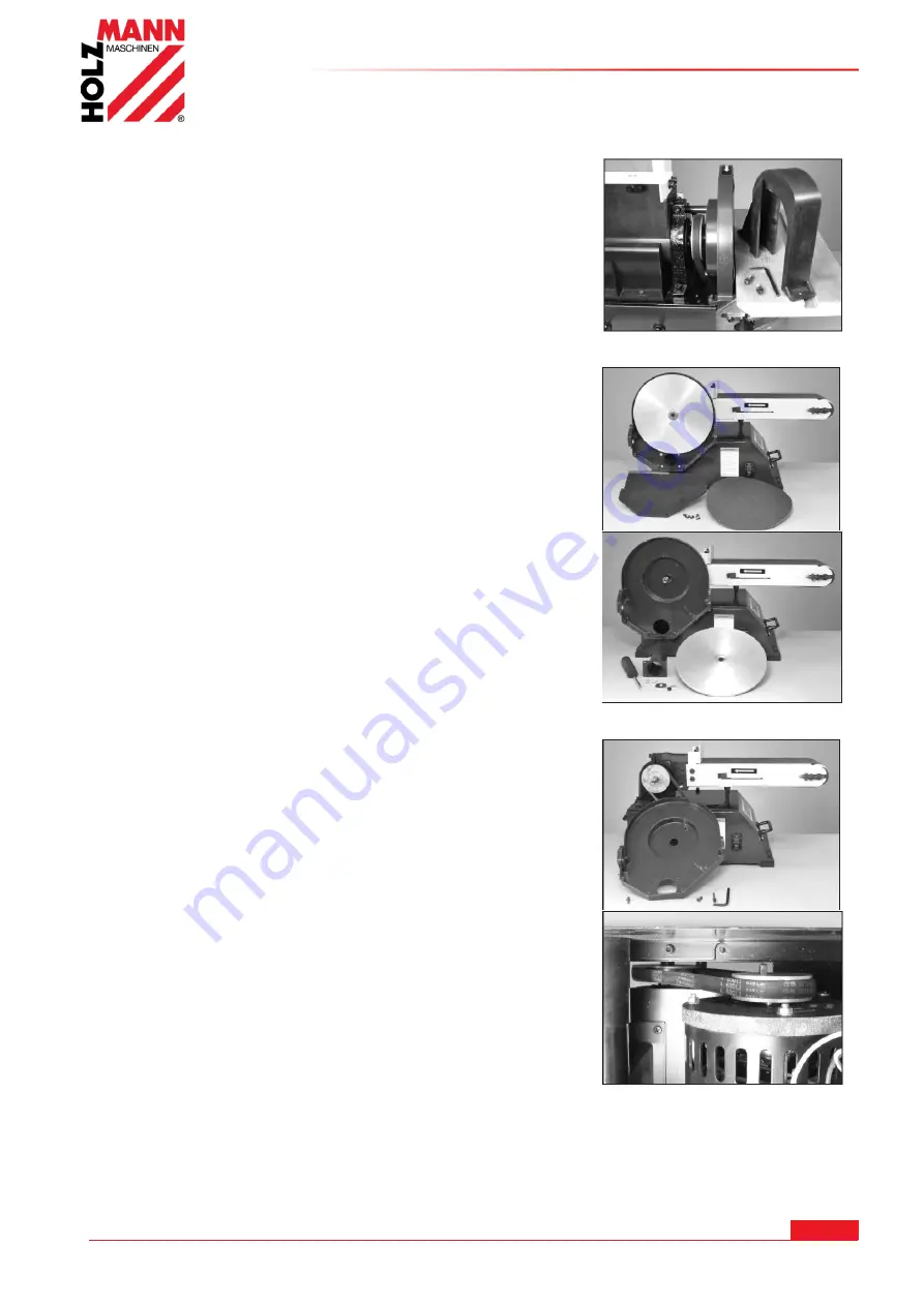
Changing V-Belt
NOTE:
Replacing the V-Belt requires that the Belt Cover, bottom
Base Cover, and whole Sanding Disc Assembly be removed in
order to gain access to the drive shafts and pulleys.
1. Remove the Belt Cover (Part #39) by unscrewing the two hex
head Screws (#112).
2. Remove the complete Sanding Disc Table Assembly from the
Disc Frame.
NOTE:
Reverse the assembly steps for installing the Sanding
Disc Table.
3. Remove the lower Disc Guard (#95) by unscrewing the six
Phillips head Screws (#33), and also the Sandpaper from the
metal Sanding Disc.
4. Remove the metal Sanding Disc (#100). Turn the center
Screw (#98) counterclockwise to remove it. Pull the large
Washer (#99) from the disc center and then pull the disc off from
the Drive Shaft (#24). Note that the disc is positioned on the
shaft with a small Key (#11).
5. Remove the Dust Connection Pipe (#102) from the lower
section of the Disc Frame with the four Phillips head Screws
(#33).
6. Unscrew the Disc Frame from the sander’s
cabinet. Remove three screws - two on top of the frame (#38)
and one longer screw from the interior of the frame (#91).
7. On the cabinet top, under the sanding belt frame, there are
two hex head Bolts and Nuts (#18, 19) that extend up from the
cabinet surface. These connect to the motor frame and will
adjust the tension of the V-Belt by pivoting the motor.
Loosen the locking nuts and then rotate the bolts so that the
motor frame is moved to release tension on the V-Belt.
To gain access to the lower drive Pulley and V-Belt, the bottom
Base Cover (#3) must be removed.
7. Carefully tip the sander to one side to avoid any damage to
the machine. Unscrew the four retaining Screws (#1) and
remove the base cover.
8. Remove the old V-belt from the two drive pulleys, and install a
new V-Belt. Make sure that there is some tension on the belt, so
that it does not slip off as the sander parts are re-assembled.
NOTE:
Both pulleys are pre-set at the factory and should be in-
line with each other. If not, re-adjust one of the pulleys on their
drive shaft. Loosen the hex set screw that holds the pulley to its
shaft, move the pulley so that it is aligned with the other pulley,
then re-tighten the set screw to lock it in position.
9. While the sander is still apart, set the belt tension. The sander
will have to be tipped back up to its normal position for this step.
10. Once the tension on the V-belt is set, re-assemble the
sander parts by reversing steps 7 to 1 above
15.5
Storage
Tension the sanding belt of the belt sander.
Store the machine in a dry and well ventilated place.
Summary of Contents for BT 1220TOP
Page 66: ......


